Preface
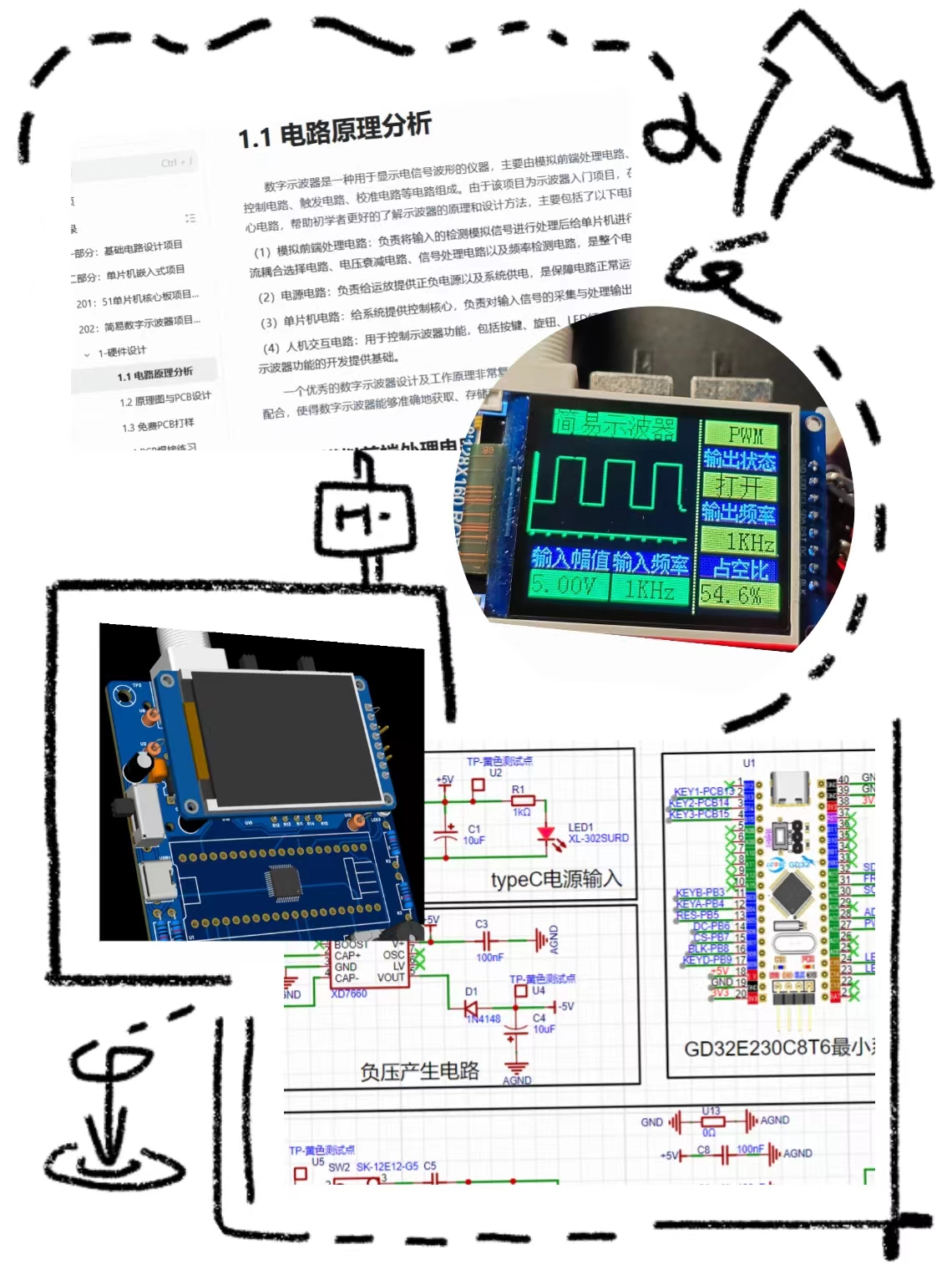
This project replicates the "LCSC Training Camp Project - Simple Digital Oscilloscope".
First of all, I would like to thank all the teachers for their teaching and guidance, and the experts in the discussion group for their enthusiastic help~
I. Hardware Design
1. Important Circuit Structure - Content Summary
Analog Front-End Circuit:
It consists of an input AC/DC coupling switching circuit, an input signal attenuation circuit, and a signal conditioning circuit.

Why add an analog front-end processing circuit? Can't we just connect the input signal directly to the microcontroller pin?
The main purpose of the analog front-end processing circuit is to convert the actual analog signal into a signal suitable for microcontroller processing. Directly connecting the input signal to the microcontroller pin has several problems:
Signal amplitude matching problem: The amplitude of the actual signal may be too large or too small, which is not suitable for the analog input range of the microcontroller. The front-end circuit can adjust the signal amplitude through the attenuation circuit.
Signal type matching problem: Microcontrollers can usually only process DC signals, while the actual signal may be AC. The AC/DC coupling switching circuit can convert the AC signal into a DC signal suitable for microcontroller processing.
Anti-interference capability: Direct connection may cause the signal to be subject to electromagnetic interference, affecting the accuracy of the measurement results. The front-end circuit can improve the signal's anti-interference capability through components such as filters.
Signal Protection: The front-end circuit can also provide overvoltage protection to prevent damage to the microcontroller from unexpected high voltage conditions.
Why add a capacitor at the input signal level, and what is its function?
Adding a capacitor at the input signal level has several main functions:
Decoupling: Capacitors can provide transient current to the circuit, reducing the impact of power supply noise on the signal, thus acting as decoupling.
Filtering: Capacitors and resistors can form an RC filter, filtering high-frequency noise and smoothing the signal.
Blocking DC components: If the input signal is an AC signal, and we only care about its AC component, then the capacitor can block the DC component, allowing only the AC signal to pass.
Signal Coupling: In multi-stage amplification or processing circuits, capacitors can achieve lossless signal coupling, avoiding the influence of DC signals on subsequent circuits.
What is the function of a signal conditioning circuit, and how should it be designed?
The main function of a signal conditioning circuit is to appropriately process the input signal, making it more suitable for subsequent detection and processing. The design of a signal conditioning circuit needs to consider the following aspects:
Signal amplitude adjustment: Based on the microcontroller's input range, design an appropriate attenuation circuit to ensure a moderate signal amplitude.
Impedance matching: Impedance matching between the signal source and the amplifier is crucial for the quality of signal transmission. The design process requires consideration of input and output impedance matching.
Filtering and denoising: Based on the signal characteristics and application scenario, design appropriate filters, such as low-pass, high-pass, or band-pass filters, to remove unwanted frequency components and noise.
Linearization: If the signal is non-linear, linearization circuits may be needed to improve signal quality.
Gain adjustment: Depending on the needs, gain-adjustable amplifiers may also be required for precise signal control and adjustment.
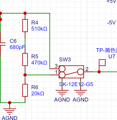
Input signal attenuation circuit :
The input signal attenuation circuit is an important component of the analog front-end processing circuit, allowing the oscilloscope to handle signals with different amplitude ranges. By understanding the working principle and design methods of signal attenuation circuits, accurate signal measurement without distortion can be ensured.
Attenuation ratio calculation:

Switch control: Understand how to select different attenuation levels using switches (such as SW2, SW3). In your example, when switches 2 and 3 are connected together, the signal flows directly into the subsequent voltage follower circuit without attenuation; while when switches 2 and 1 are connected together, the signal is attenuated through a resistor divider network.
Signal amplitude measurement: Understand how to calculate the actual input signal amplitude based on the attenuation ratio. According to the information you provided, when switches 2 and 3 of SW2 are connected together, the measurable input signal amplitude is -1.6V to -5V; when switches 2 and 1 of SW2 are connected together, the measurable input signal amplitude is -80V to 250V.
Circuit Protection: Understand how to use attenuation circuits to protect the oscilloscope input. When the amplitude of the input signal is uncertain, you can first use the high-voltage range for measurement. If the signal is found to be within the measurement range of the low-voltage range, then switch to the low-voltage range for more accurate measurement.
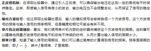
Hysteresis Comparator Circuit: A hysteresis comparator is a special type of voltage comparator with two threshold voltages, one to trigger a high output level and the other to trigger a low output level. This design prevents the output voltage from frequently switching between high and low levels when the input signal voltage is close to these two thresholds, thus improving the circuit's anti-interference capability.

2. PCB Design

Straight-Line Routing Principle: Try to keep traces as straight as possible to reduce signal propagation delay and reflection. If bends are necessary, prioritize using 135° obtuse angles or rounded corners to reduce signal discontinuities and electromagnetic interference. Avoid using right angles, as they can cause signal reflections and impedance discontinuities.
Trace width selection: Power lines carry higher current, so their width should be greater than signal lines to reduce resistance and voltage drop. In your project, signal lines should be 15mil wide, and power lines 20mil wide. This ensures stable power supply while minimizing signal loss.
Prioritize top-level routing: Top-level routing facilitates observation and maintenance. If a top-level trace encounters an obstacle, it can be connected to the bottom layer via a via to continue routing. If the bottom-level trace is also blocked, a via can be placed to switch back to the top layer.
Ground handling: AGND (analog ground) and GND (digital ground) should be copper-plated separately and separated at a 0-ohm resistor. This helps reduce interference between analog and digital sections. The copper plating area needs to be adjusted based on the actual PCB layout.
Eliminate flying wires: After copper plating, any unconnected flying wires can be eliminated by placing vias for the corresponding nets at the flying wire locations, adjusting the trace positions, or manually connecting them. Ensure all nets are correctly connected.
Adding Teardrops: After routing is complete, you can select "Add Teardrops" in the "Tools" menu to strengthen the connection between the pads and the traces, improving soldering reliability. After adding teardrops, perform copper pouring. If the traces are moved or adjusted, use the shortcut Shift+B to rebuild the copper pour.
II. Software Design
1. Main Function
Key Scan Processing Function (Key_Handle(&oscilloscope)): This line of code calls a function named Key_Handle, which is likely used to detect and process user commands input via keystrokes. oscilloscope may be a structure containing oscilloscope status information and configuration parameters.
Data Acquisition and Conversion: When the oscilloscope.showbit flag is 1, it indicates that the ADC (Analog-to-Digital Converter) has acquired voltage values, and the program begins processing these data. First, set showbit to 0 to reset vpp (peak-to-peak value) to 0. Then, through a loop (for(i=0;i), the program reads raw data from the ADC and converts it into a voltage value. The Get_ADC_Value(i) function is used to obtain the ADC value, which is then multiplied by a scaling factor (3.3f/4096.0f) to get the actual voltage value. Then, the actual voltage value is calculated using a formula (5-(2.0f*adcValue)) and stored in the oscilloscope.voltageValue array. Simultaneously, the program updates oscilloscope.vpp, recording the maximum peak-to-peak voltage acquired.
Trigger level and gain determination: The program determines the trigger position (Trigger_number) by looking up the value in the voltageValue array to correctly display the waveform on the screen. If vpp is less than 0.3 volts, the program stops acquiring data. If vpp is greater than 0.3 volts, the program calculates the gainFactor to display the waveform on the screen at an appropriate scale.
Waveform display: After determining the trigger level and amplification, the program displays the waveform. It displays 100 data points following the Trigger_number position in a loop. Within the loop, it checks if the button is pressed (KEYD); if so, it stops data acquisition. Then, based on whether the voltage value exceeds the median value, the program calculates and stores the adjusted voltage value. This adjusted value is used in the drawCurve function, which is responsible for drawing the waveform on the screen.
Parameter display UI (TFT_ShowUI(&oscilloscope)): Finally, the TFT_ShowUI function is called to display the oscilloscope's user interface on the touchscreen.

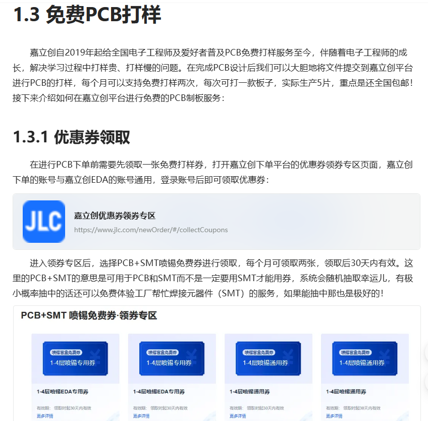
III. Free Prototyping (Important! ٩(๑>◡)
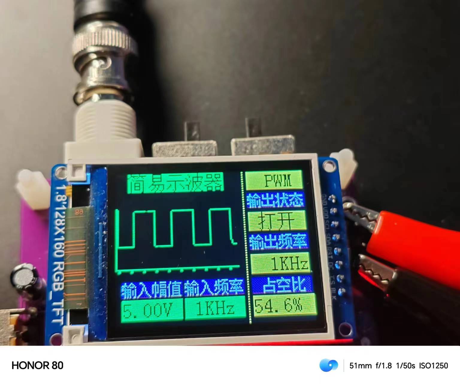
Physical Verification
: Waveform Display: Draws waveforms on a 1.8-inch TFT screen.
Zoom Function: Adjusts waveform zoom using a knob.
Pause Display: Pauses real-time waveform updates using buttons.
Square Wave Output: Outputs square wave signals at frequencies of 1K, 2K, and 4K and displays them on the screen.
Duty Cycle Adjustment: Adjusts the duty cycle of the square wave using buttons.
Frequency Measurement: Measures and displays the frequency of the input signal.


 京公网安备 11010802033920号

 MBRA120T3


