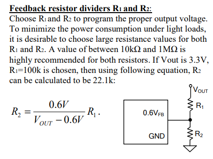
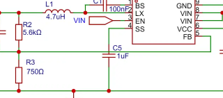
 supports 4.5V-30V input voltage. R2 and R3 in the schematic correspond to R1 and R2 in the datasheet for adjusting the output voltage. The datasheet recommends using resistors with a value of 10kΩ to 1MΩ. It is recommended to adjust the 5V output before soldering the 3V3 section. M3 screws are screwed into the holes on
 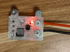 back , and
 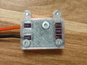 sides
sides  of the casing to ensure the wires are flush with the pads; soldering is not required in these cases.
All reference designs on this site are sourced from major semiconductor manufacturers or collected online for learning and research. The copyright belongs to the semiconductor manufacturer or the original author. If you believe that the reference design of this site infringes upon your relevant rights and interests, please send us a rights notice. As a neutral platform service provider, we will take measures to delete the relevant content in accordance with relevant laws after receiving the relevant notice from the rights holder. Please send relevant notifications to email: bbs_service@eeworld.com.cn.
It is your responsibility to test the circuit yourself and determine its suitability for you. EEWorld will not be liable for direct, indirect, special, incidental, consequential or punitive damages arising from any cause or anything connected to any reference design used.
Supported by EEWorld Datasheet
EEWorld
subscription
account

EEWorld
service
account

Automotive
development
community

Robot
development
community

About Us Customer Service Contact Information Datasheet Sitemap LatestNews


Room 1530, 15th Floor, Building B,
No.18 Zhongguancun Street,
Haidian District,
Beijing, Postal Code: 100190
China
Telephone: 008610 8235 0740
 京公网安备 11010802033920号

 2200GAH1002B3GB


