Preface:
Currently, most chargers with PD 100W or higher power ratings cost around 100 RMB even when found as cheap scraps, while computer power supplies are readily available and inexpensive for most people. Compared to AC-DC, a direct DC-DC converter significantly reduces DIY costs and can operate normally at full load for extended periods.
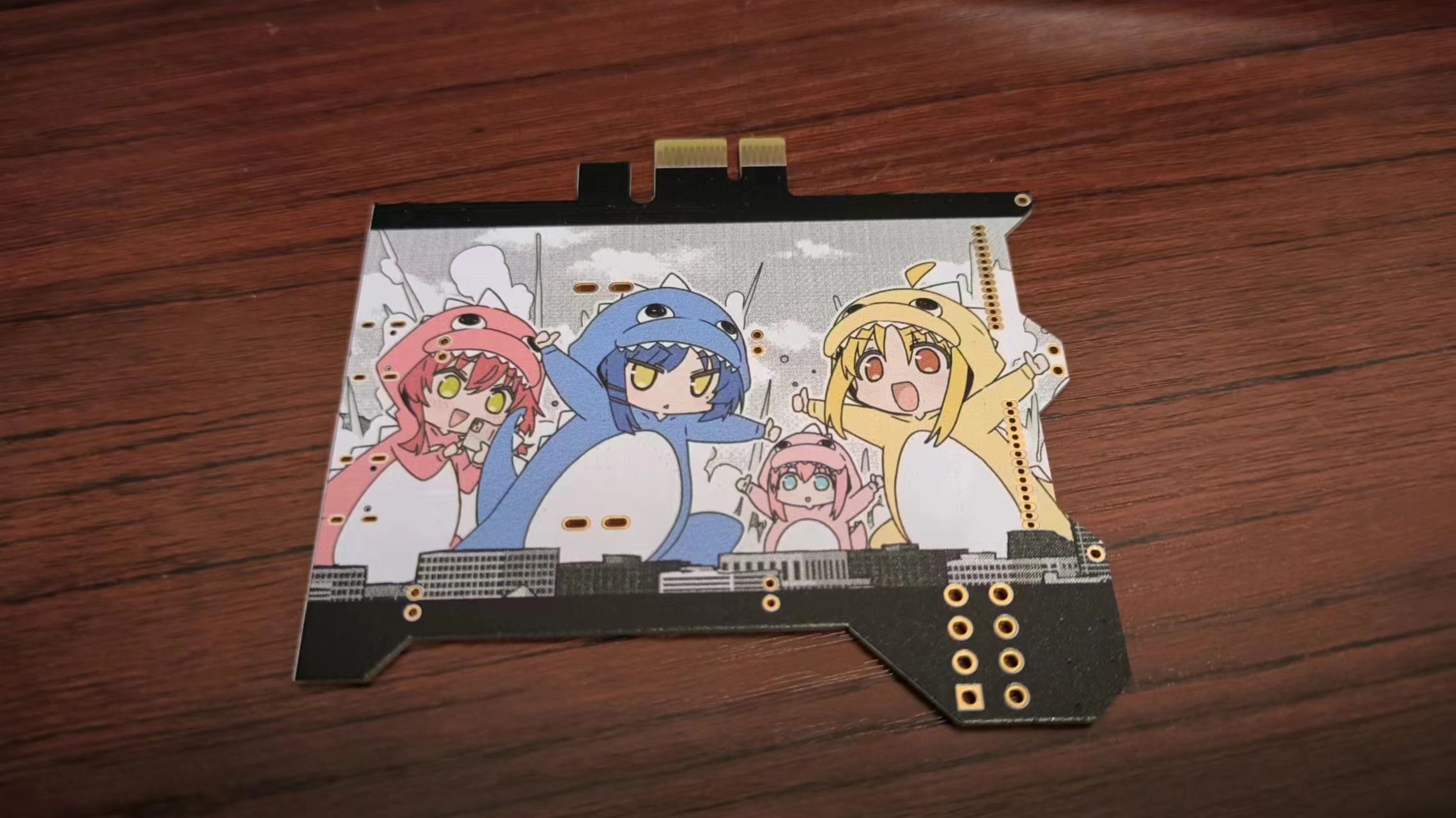
Since I got a free color silkscreen printing coupon, I used a "Lonely Rock" color silkscreen print; if you don't need it, just place your order normally.
The circuitry of this project is essentially the same as a
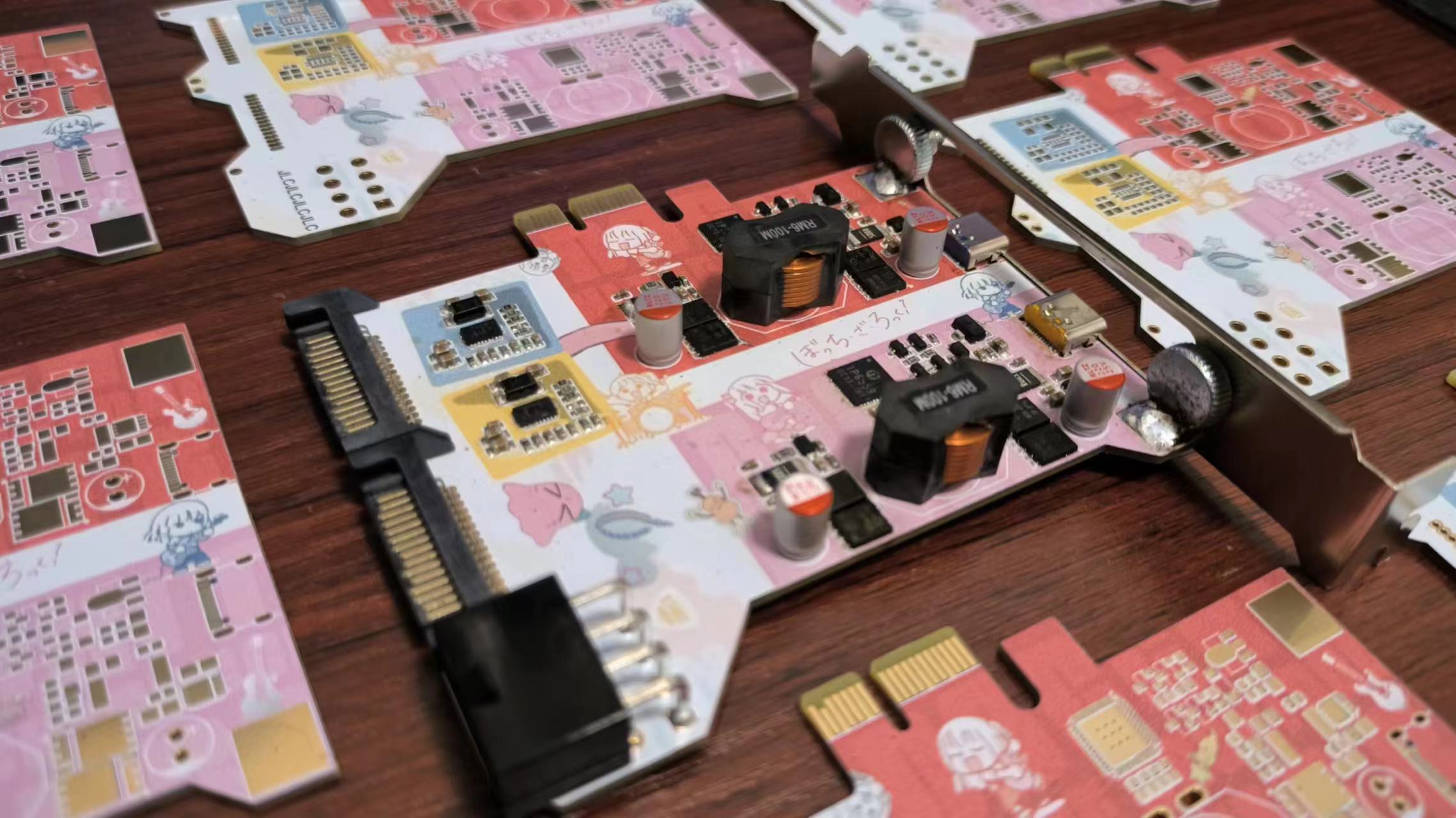
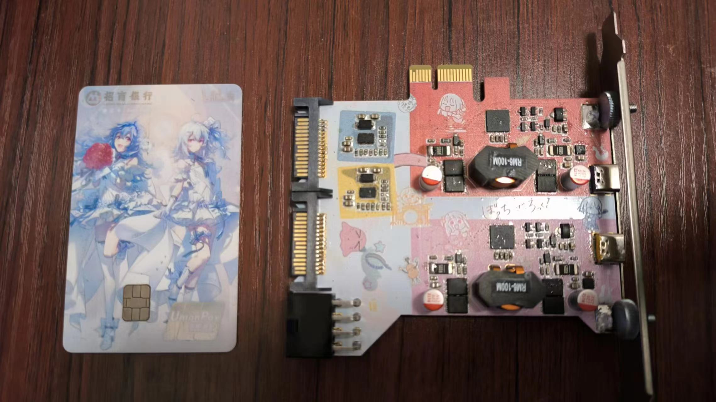
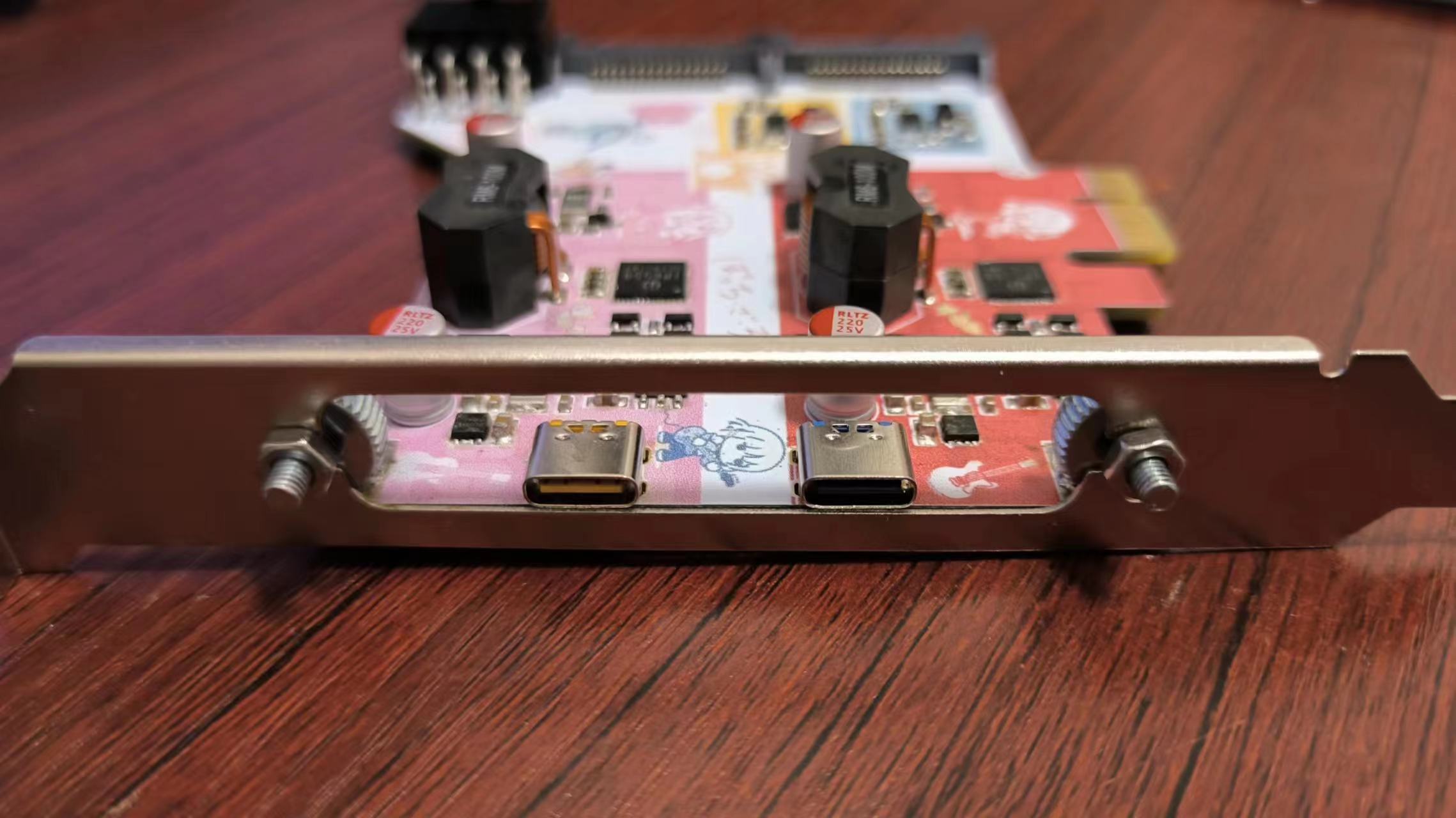
200W desktop power supply with dual C and dual A ports : - uses fuse chips to prevent circuit burnout due to insufficient power supply - conversion efficiency up to approximately 97% - input voltage range 9-24V. Two single C ports, each supporting up to PD 100W output - uses an 8-pin connector from a computer graphics card and two SATA 15-pin connectors for power, suitable for various interface configurations. The appearance, materials , circuitry , and components can be directly referenced from the BOM (Bill of Materials). The total cost is approximately 80 RMB, with components chosen primarily for affordability. The PCB thickness is limited to 1.6mm to fit into a PCIe slot. I will share the shopping cart link later; just select it to place your order. Step 1: Soldering the Power Supply Interface and Fuse Circuit. There's nothing particularly noteworthy about this part, except that the SATA pads are too close together and prone to solder bridging. Soldering the fuse circuit is unnecessary in the following situations: 1. Using an 8-pin graphics card connector [an 8-pin connector alone is sufficient to support 200W input, but full coverage is better]. 2. Ensuring both SATA 15-pin connectors are securely inserted, and that the total continuous power does not exceed 120W [a single SATA power connector's 12V continuous total power is approximately 60W]. Step 2: Soldering the IP6559 Main Circuit . There's nothing particularly noteworthy about this part either. After soldering, ensure there are no short circuits and test with a 9-24V power supply at a current limit of 0.1A to prevent short circuits and burnout. Step 3: PCIe Slot Installation. Installing a PCIe slot cover is mandatory; in actual use, connecting cables will cause the PCB to protrude from the PCIe slot. However, since suitable PCIe slot covers (with suitable hole positions, reasonable prices, and the ability to be fixed to the PCB) are unavailable, I considered buying a large-aperture bracket and securing it with screws, primarily because it's inexpensive. First, secure the hand-tightened screws and nuts to the baffle before soldering. Soldering stainless steel may require stainless steel solder flux. Temperature will be tested later; you can refer to the 200W desktop power supply with dual C and dual A ports . Since it operates in BOOST mode, the actual heat generation should be much lower. Ripple is almost identical to the 200W desktop power supply with dual C and dual A ports; please refer directly to the reference. Efficiency is almost identical to the 200W desktop power supply with dual C and dual A ports; please refer directly to the reference. Precautions & Issues: 1. MP5021 is very difficult to buy; many stores were out of stock after placing the order. Therefore, shorting it is still recommended. 2. The PCIe slot has 12V power supply, which can share the external power supply pressure. However, a current limiting circuit is needed, so it was not used [but connected to GND]. 3. The grounding resistance of pin 37 determines the output protocol of port C. Connecting an NTC can provide temperature protection, but a suitable NTC was not found. A resistance value of around 130KΩ is sufficient to output 100W. Lower resistance values will reduce power, while higher values won't reach 100W. 4. After soldering the ORING circuit, I found it somewhat impractical: firstly, I wouldn't connect two inputs simultaneously for my own use; secondly, even the most ideal diode won't be ideal, and the chips are expensive. —Later, I simply disassembled the ORING circuit and shorted the two ends of the MOSFET. 5. The BSC059N04LS6 was the most suitable MOSFET I found, but unfortunately, all the ones I bought were counterfeit. I had to use AON6354 and BSC0906NS instead, and I tried to buy used parts. 6. Although the VOOC pin is still available, none of the chips I can currently buy support it. I'm thinking of combining it with a PCIe to USB chip [such as VL822] to create a full-featured Type-C port. I wonder if such a combination chip exists. I wonder if it's feasible to connect PD and VBUS to the fast charging circuit, and the three pairs of data signals to the VL822 [VL162: ???].


 京公网安备 11010802033920号

 DR300
DR300


