Circuit Design Section:
In the circuit design section, compared to the previous circuit, I changed the battery power supply in the lithium-ion charging and discharging circuit to a single 18650 battery power supply, and added a toggle switch to prevent accidental power-on when not in use.
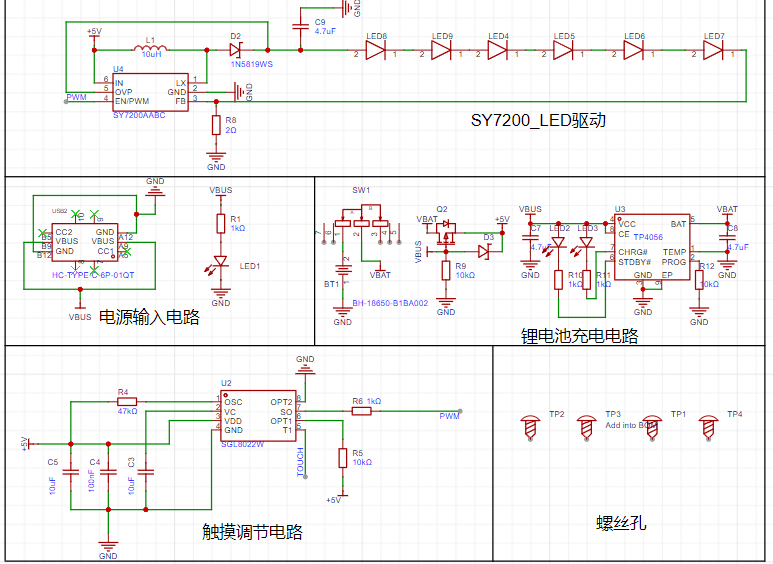
1. Power Circuit:
The power circuit mainly consists of a TYPE-C interface and a power indicator light. It uses a 2-pin TYPE-C interface, which is simple, convenient, and easy to solder. R1 is used as a current-limiting resistor for the power indicator light, and LED1 is used as the power indicator light, which lights up when the switch is closed to indicate power.
2. Lithium Battery Charging and Discharging Section:
First is the power switching circuit, which consists of a P-channel MOSFET, a pull-down resistor, and a diode. When the TYPE-C interface is connected, 5V comes in, and the gate voltage of the MOSFET is 5V. After passing through a 1N5819 Schottky diode, the VCC voltage is 4.4V, which is 4.4V at the source. This does not meet the conduction condition, and the battery power cannot be supplied. When the TYPE-C interface is disconnected, the gate (G) is brought down to low. Due to the presence of the body diode, the source (S) will have a voltage of approximately 3.5V, meeting the requirements. At this time, the MOSFET turns on, and the battery powers the subsequent circuits. Thanks to the 1N5819 Schottky diode, the current will not flow back. A TP5056 lithium battery charging chip charges the battery. When the TYPE-C interface is connected, the lithium battery is charged simultaneously to ensure sufficient power. LED2 serves as a charging status indicator, and R11 is the charging current feedback resistor. Changing the resistance of R11 changes the overall charging current.
3. The touch adjustment circuit
uses an SGL8022W touch adjustment chip. A 1K resistor is added to the touch line to increase the stability of touch sensitivity and make it more accurate.
4.
The LED light circuit uses six 26mm LED ceramic filaments, controlled by a SY7200AABC chip. The number of LED ceramic filaments can be increased or decreased as needed.
Precautions:
1. The shape of the required light-transmitting portion must be drawn on the bottom solder mask layer. Copper should not be laid on the bottom surface, and traces and copper should not be laid on the top surface, as this will affect the effect.
2. If making a color silkscreen PCB, you can first verify it using a free standard PCB and adjust its light transmittance.
3. The section of the LED ceramic filament with the rectangular hole is the positive electrode
. 4. If the lithium battery charging circuit is not needed, simply delete it and modify the identifier to complete
the PCB.

PDF_PCB Touch Adjustable Lighting Diagram—Walnut.zip
Altium_PCB Touch Adjustable Lighting Picture—Walnut.zip
PADS_PCB Touch Adjustable Lighting Picture - Walnut.zip
BOM_PCB Touch Adjustable Lighting Illustration—Walnut.xlsx
95898
electronic


 京公网安备 11010802033920号

 TN-171


