The STM32F103 development board features a color silkscreened
PCB with numerous peripherals and a wide range of interfaces.
Serial port, ST-LINK, and USB are all brought out . It includes
an SRAM
MCU, LCD screen,
SD card slot
, W25Q
AT24
LED
buttons , and
all I/O
pins are provided. The screen interface is identical to that of the Liangshanpai screen, allowing it to be directly mounted on the back of the Liangshanpai screen as a full-screen development board.

PDF_STM32F107ZET6 Minimum System Development Board.zip
Altium_STM32F107ZET6 Minimum System Development Board.zip
PADS_STM32F107ZET6 Minimum System Development Board.zip
BOM_STM32F107ZET6 Minimum System Development Board.xlsx
95916
CAN splitter board for Klipper 3D printer RRF CANbus communication line organization
A CAN bus switchboard similar to Fly3D is used for Klipper RRF CANbus communication line organization in 3D printers.
[FLY Product Link](https://item.taobao.com/item.htm?abbucket=12&id=731000996143&ns=1&spm=a21n57.1.0.0.1d2c523cdJ8ZhQ)
is just an ordinary CAN busbar.
FLY sells it for 25+5 (the ever-present shipping fee), but I got it from LCSC for free, and with the components I bought myself, the cost is less than 10 yuan. It's great ! If you're too
lazy to buy components and solder, you can find it on Xianyu (a second-hand marketplace) for around ten yuan with free shipping
. Actually, I designed this board for someone else! Hahaha! ~~
*****
To add a logo to the board, please select according to this image
! [image.png]

and then select **Do not confirm production draft**
PDF_CAN splitter board for 3D printer Klipper RRF Canbus communication line organization.zip
Altium_CAN splitter board for Klipper 3D printer RRF Canbus communication line organization. zip
PADS_CAN splitter board for Klipper 3D printer RRF Canbus communication line organization. zip
BOM_CAN splitter board is used for Klipper 3D printer RRF Canbus communication line organization.xlsx
95917
DSP programming conversion board
Programming converter board for TI DSPs
The J-LINK to DSP programming converter
board provides a TYPE-C interface to convert 5V to 3.3V for TI DSP power supply
. The board also provides a standard 7*2PIN J-Link interface to convert J-Link to the corresponding pins of TI DSP,
such as TMS, TDI, TDO, TCK, etc.,
making it convenient to use J-LINK to program TI DSPs.
PDF_DSP Programming Converter Board.zip
Altium_DSP programming conversion board.zip
PADS_DSP Programming Conversion Board.zip
95918
Balance bike
The base of the balance car
The STM32 self-balancing scooter's drive base uses the TB6612 chip to drive the motor. The power supply uses a pre-built voltage regulator module and an LDO. The gyroscope is an MPU6050, with one serial port, one download interface, and two motor interfaces.
This is an improved version; the gyroscope module can now be screwed in for greater stability.
As for the code, I learned it on Bilibili, so I won't post it here—there's plenty of information available QAQ.
VID_20231028_153432.mp4
PDF_Swiss Bike.zip
Altium_Balance Car.zip
PADS_Balance Car.zip
95919
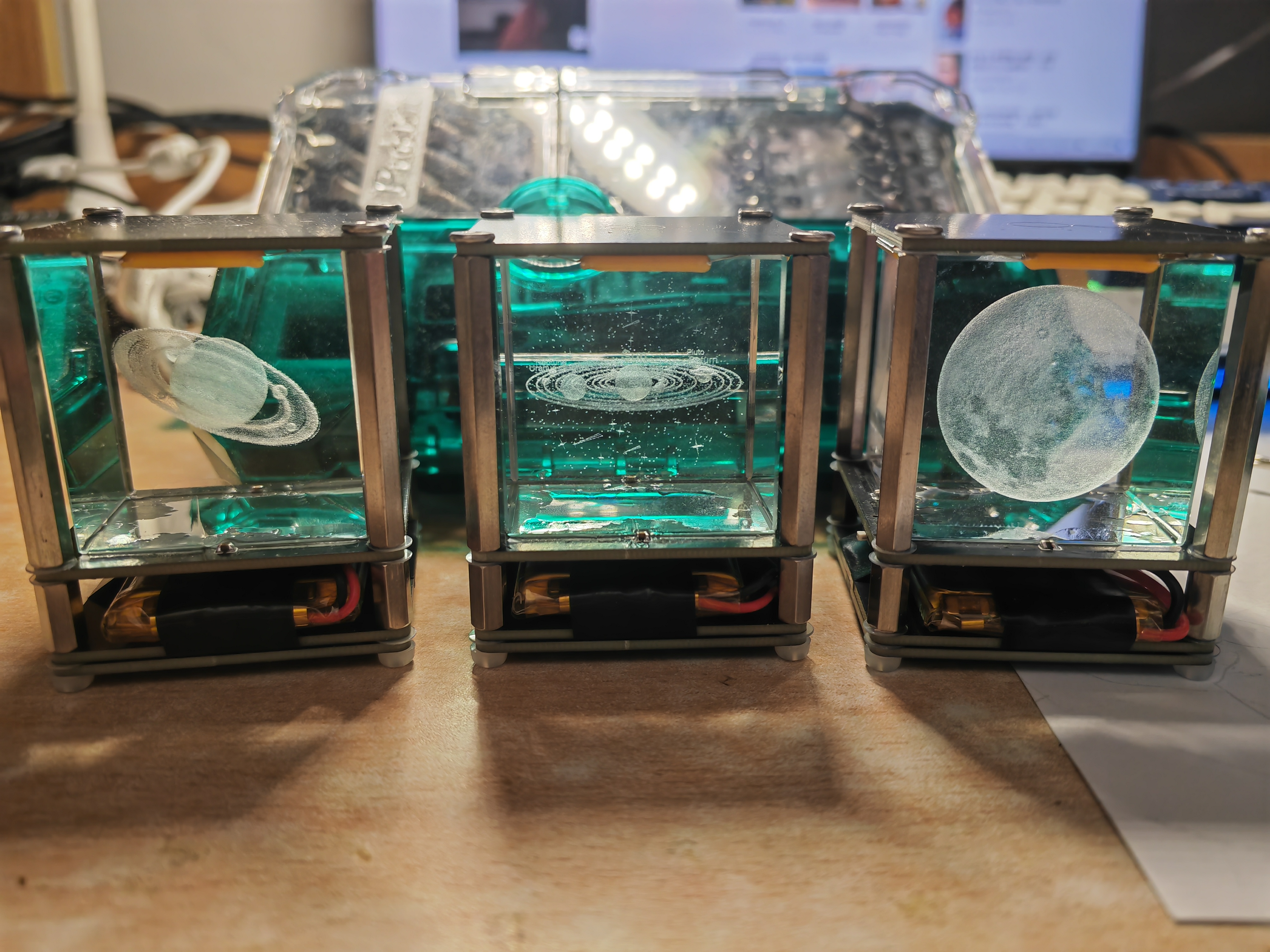
Touch Crystal Night Light
Inspired by the nightlights made by other content creators on Bilibili, I designed my own touch crystal nightlight (a great gift for your girlfriend).
--------------------------------------------------------------------------------
Four M3*40+4 stainless steel studs, stainless steel studs, hexagonal studs;
four M3*10 stainless steel studs; 304 stainless steel double-through hexagonal stud screws;
four M3 bolts (top selection, length approximately 5mm)
; four nylon M3 bolts (bottom selection must be non-conductive); Phillips head nylon screws;
several nylon plastic washers; M3*6*0.3 nylon washers; rubber plastic washers;
lithium battery size recommended: 1500mAh, size 50*34*7, 3.7V; small polymer lithium battery.
Other components can be purchased according to the BOM.
The crystal ornament in the center can be bought from this store; it's relatively inexpensive. A small, healing item for when you're bored and looking at rainy clouds; a small crystal ornament for computer desktop; a birthday gift.
--------------------------------------------------------------------------------
Assembly:
--------------------------------------------------------------------------------
I encountered many pitfalls during assembly, so I'll point out the points to note here to help everyone assemble.
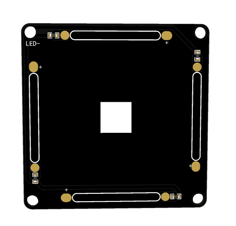
The two sides shown in the image are the light panel and the base, respectively. These two sides should face down during assembly. Note that the "LED-" symbol in the upper left corner of the light panel must correspond to the "LED-" symbol on the base; the orientation is crucial.
During assembly, I used stainless steel pillars to connect the upper and lower base plates instead of wires. However, the holes I pre-drilled were slightly too large, which may cause poor contact during direct installation. Therefore, I suggest applying a little solder to the holes and then firmly screwing in the bolts. However, be careful not to screw directly in, as the stainless steel pillars can easily scratch the solder mask layer; therefore, always use nylon washers.
The PCB used for the bottom fixing, whether it's the light panel's PCB or the base's PCB, must correspond to the markings on the top. Also, the bottom bolts must be nylon; using metal bolts will cause malfunctions.
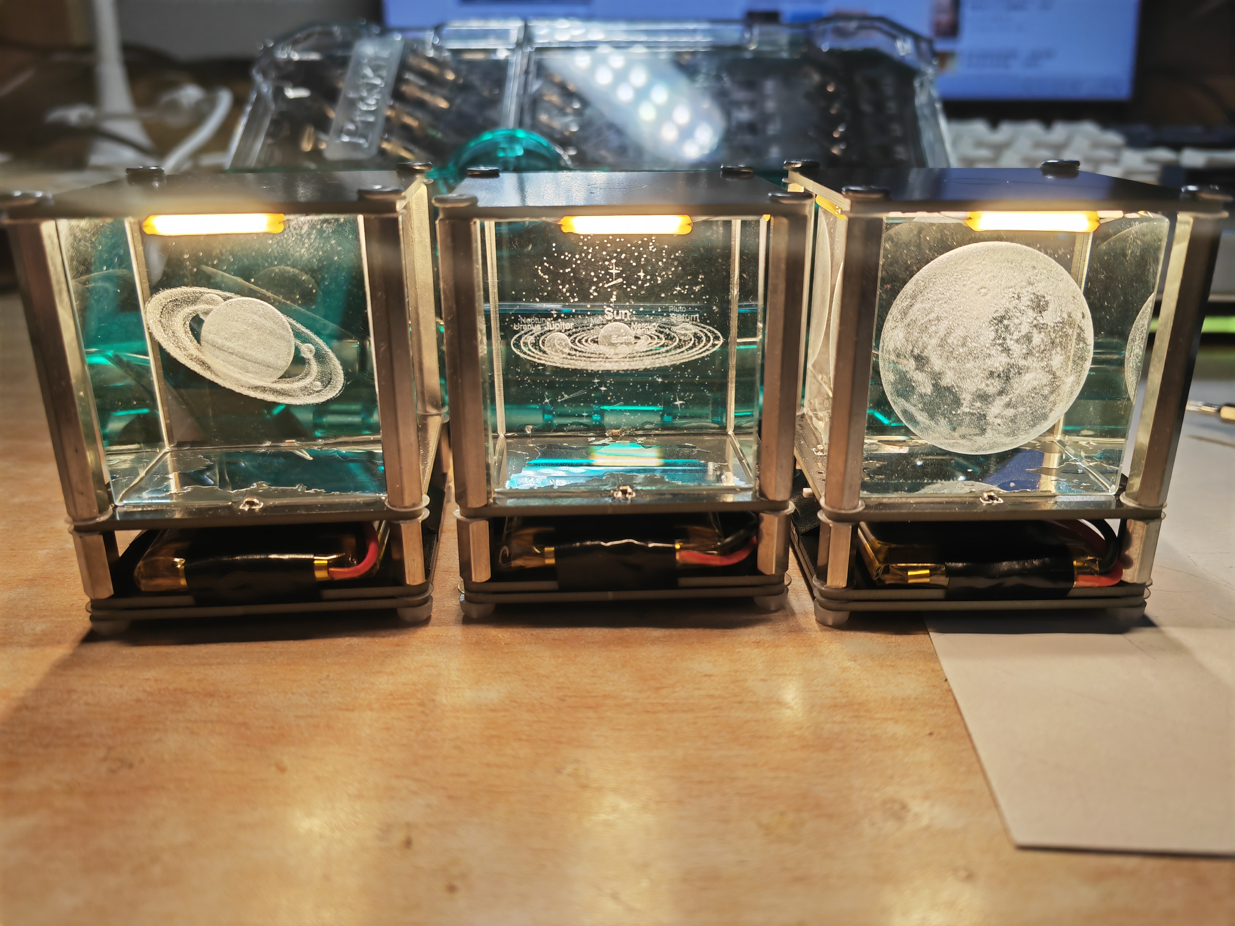
Looking at the finished
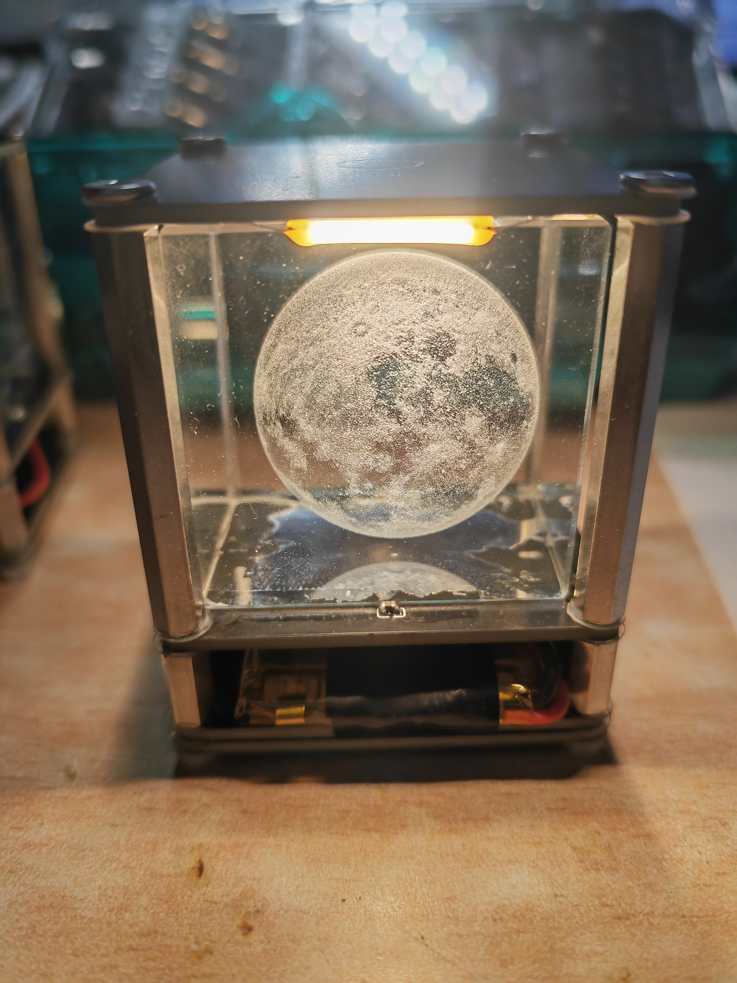
crystal, although four capacitors are used for fixing, the crystal is still somewhat wobbly, especially with the added plastic washers. Therefore, you can also use super glue (502) to attach the crystal to the board.
VID_20240223_225347.mp4
PDF_Touch Crystal Night Light.zip
Altium Touch Crystal Night Light.zip
PADS Touch Crystal Night Light.zip
BOM_Touch Crystal Night Light.xlsx
95921
WIFI relay
The WIFI relay developed based on ESP8285 uses the MQTT communication protocol. The protocol content can be customized, and the MQTT server address and user can be configured by logging into the device's web management backend.
1. Equipment Description
1.1 Appearance
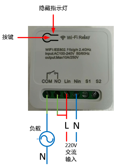
1.2 Power Supply:
100~240V AC input, Lin connects to the live wire, Nin connects to the neutral wire.
1.3 Load Connection:
The output signal is a passive relay signal, used for signal on/off control. It can handle a maximum load current of 10A. COM is the relay common terminal, NO is the relay normally open terminal, and the default state upon power-on is off.
1.4 Indicator Light Status Description:
There are three LED indicators: red, green, and blue. The corresponding device states are as follows:
Red light flashing rapidly: Waiting for network configuration Red light flashing slowly: Connected to the router, connecting to the MQTT server; Red light on: Connected to the MQTT server;
Blue light flashing once: Button pressed for more than 5 seconds;
Green light on: Relay on;
Green light off: Relay off.
1.5 Button Operation
: Short press for 1 second and release: Switch relay state;
Long press for 5 seconds: Device enters network configuration mode.
2. Function Operation
2.1 Connecting to the Wi-Fi router
requires using a mobile phone to run network configuration software. First, install the esptouch software on your phone. It only supports Android systems. Software download link: https://github.com/EspressifApp/EsptouchForAndroid/releases/tag/v2.0.0/esptouch-v2.0.0.apk
The network configuration steps are as follows:
Power on the device;
Press and hold the button for 5 seconds (release after the blue light flashes rapidly). At this time, the device enters network configuration mode;
Connect the phone to the router;
Launch the esptouch software on the phone and select EspTouch;

Enter the router password in the password box and then click confirm;
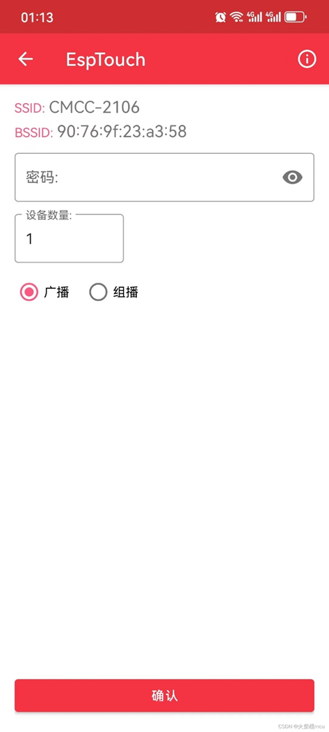
After successful network configuration, the EspTouch software will display the device's BSSID (MAC) and the LAN IP address assigned to the device by the router. You need to record the IP address for logging into the device's web management backend.

2.2 Web Management Backend
2.2.1 Login
Launch a mobile phone or computer browser on the same local area network. Enter the current device's IP address in the address bar, such as 192.168.10.103, and click to enter:
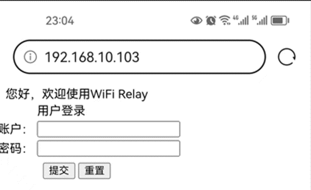
Username: admin
Default password: 123456
2.2.2 Change login password
Select the "USER" option in the directory bar:
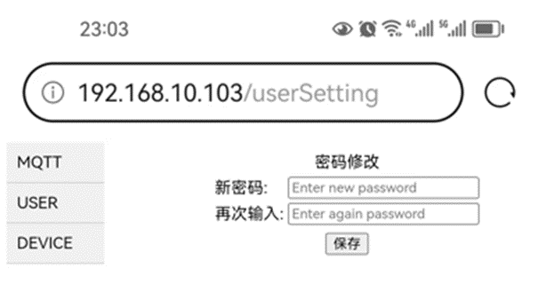
2.2.3 Configure MQTT server
Select the "MQTT" option in the directory bar:

The default server HOST: broker.emqx.io, port: 1883, is a free MQTT server that can be used for testing.
2.2.4 View device information
Select the "DEVICE" option in the directory bar:

WIFI Relay Communication Protocol - Official Version V1.5.pdf
Demo video.jpg
source code.txt
PDF_WIFI relay.zip
Altium_WIFI relay.zip
PADS_WIFI relay.zip
95922
Van Gogh Starry Night PCB
This is not color silkscreen printing, but rather an artistic artwork created using LCSC EDA's image insertion function, combining silkscreen, solder mask, and copper foil.
Color extraction code with comments is also included; you can choose your own image to create the artwork.
Bilibili video: https://www.bilibili.com/video/BV18H4y1L7UY
I saw a PCB board from The Great Wave off Kanagawa and thought it was pretty cool, so I made one myself.
Reference video for the PCB design from The Great Wave off Kanagawa: https://www.bilibili.com/video/BV1Lu411Y75b
Project link for The Great Wave off Kanagawa: https://oshwhub.com/c7h10n2/ukiyoe
I've also included the color extraction code, with comments. You can choose your own images to create your own.
The code is in the compressed file .
Requires a Python OpenCV runtime environment; the appropriate CPU version is fine.
Starry Sky.zip
PDF_Van Gogh Starry Night PCB.zip
Altium_Van Gogh Starry Night PCB.zip
PADS_Van Gogh Starry Night PCB.zip
BOM_Van Gogh's Starry Night PCB.xlsx
95923
Bluetooth console - ch9140 version
Bluetooth console cable
This project was modified based on the work of the expert Yiruhua and the schematic provided by swtbh in the comments section. Since the switch's console port lacks serial flow control, the CTS and RTS interfaces were deleted and left empty. After soldering the initial solution, the CRT tool was found to be unresponsive. Reversing the 3rd and 6th pin wiring of the network cable resolved the issue. Therefore, in this version, the SP3232 RX and TX labels were swapped, and testing confirmed it worked correctly.
PDF_Bluetooth console-ch9140 version.zip
Altium Bluetooth console - ch9140 version.zip
PADS Bluetooth console-ch9140 version.zip
BOM_Bluetoothconsole-ch9140 version.xlsx
95924
Project 3: 51 Microcontroller Development Board
This project is Project 3 of the textbook "Case Study Tutorial for Electronic Product Design (Micro-course Edition) - Based on JLCPCB EDA (Professional Edition)": 51 Microcontroller Development Board.
I. Project Introduction
Through the study and creation of the "51 Microcontroller Development Board" project case, you will become familiar with the functions and design methods of multiplexed blocks, complete the corresponding PCB design, and master the top-down and bottom-up multiplexed block design methods and bus drawing methods. Note that this circuit is not particularly complex and can be designed without using multiplexed blocks.
II. Overall Scheme
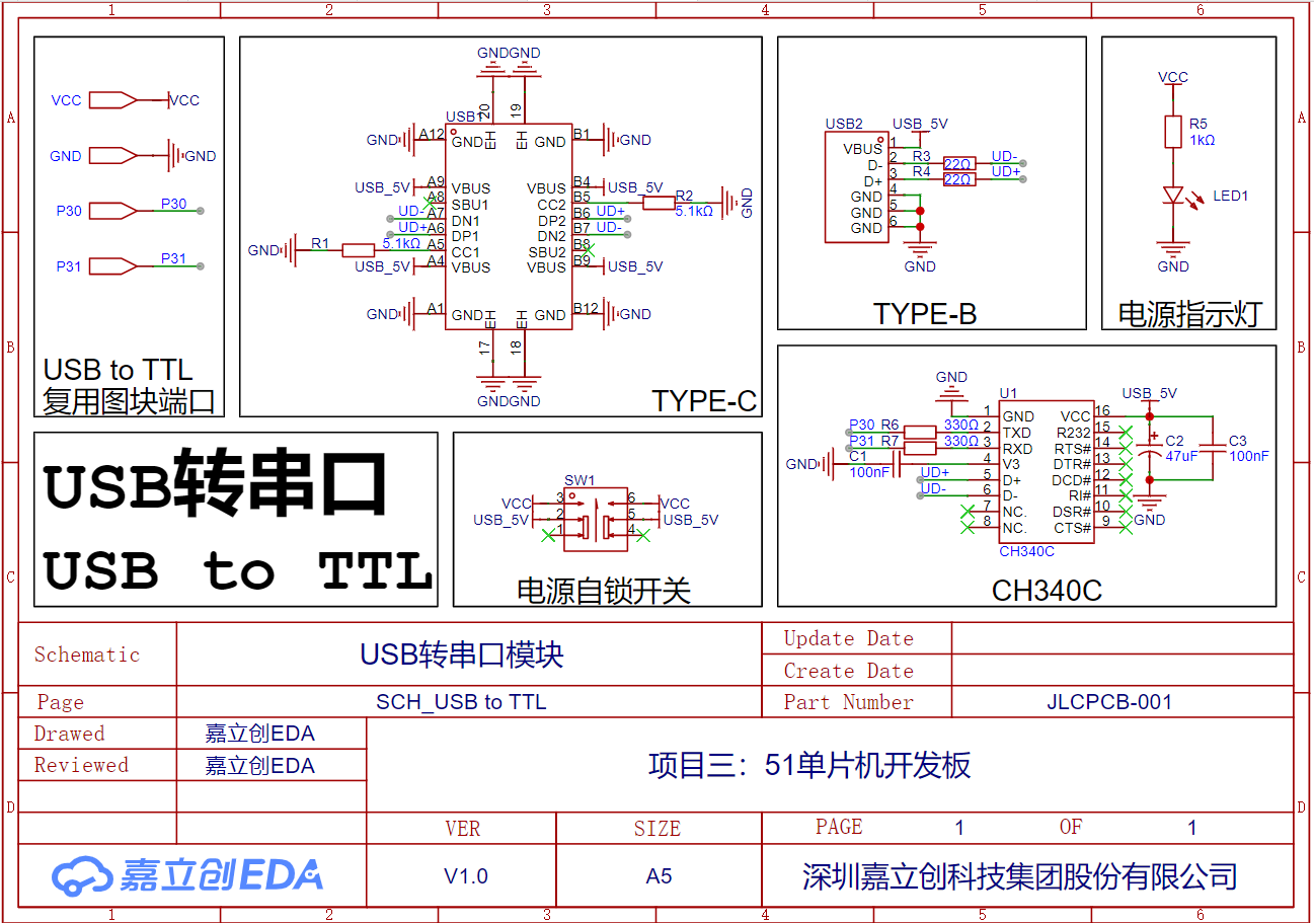
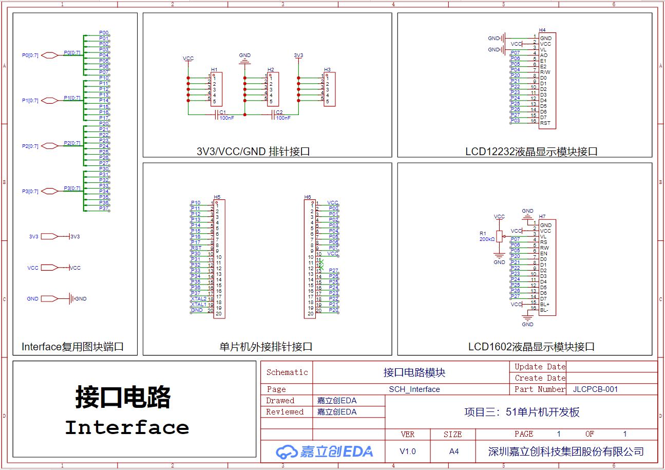
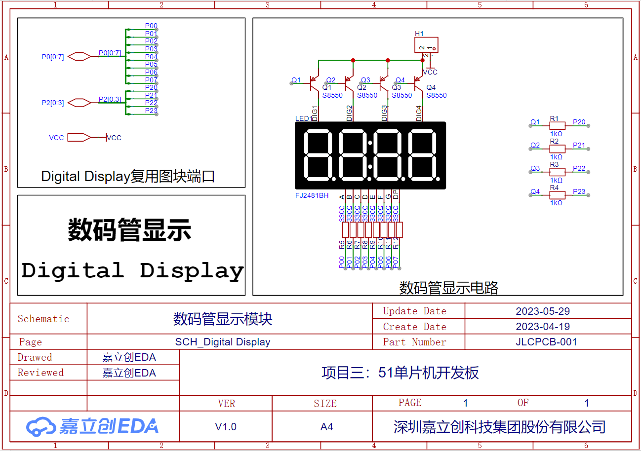
Functionally, the 51 microcontroller development board can be divided into six parts: microcontroller module, USB-to-serial port module, interface circuit module, hybrid circuit module, digital tube display module, and timer module. The connection relationships of each circuit module are shown in the system block diagram. The following uses multiplexed blocks to design and implement the circuit schematic of the 51 microcontroller development board.
Schematic

System Block Diagram

Microcontroller Module

USB-to-Serial Port Module
Interface Circuit Module
Hybrid Circuit Module

Digital Tube Display Module
Timer Module

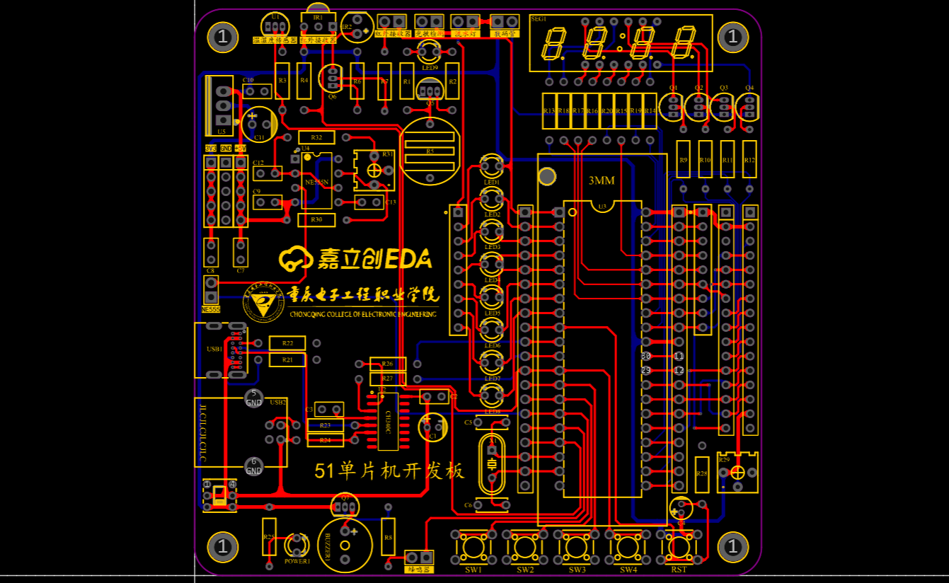
PCB
3D Rendering

Actual Image

Bill of Materials.xlsx
PDF_Project 3: 51 Microcontroller Development Board.zip
Altium_Project 3: 51 Microcontroller Development Board.zip
PADS_Project 3: 51 Microcontroller Development Board.zip
BOM_Project 3: 51 Microcontroller Development Board.xlsx
95925
electronic


 京公网安备 11010802033920号

 GNOB
GNOB


