It can also be called PY32F002B, QFN20 package, available on Taobao for 5 cents with free shipping, and has no silkscreen printing on the surface.
I think the QFN20 packaged Cortex-M0+ microcontroller, which costs only 50 cents, is quite cost-effective. It has advantages in package size, supports 5V power supply, and has a decent number of I/O pins.
[Update]:
2024-02-28: Modified the QFN package, lengthened the pin pads for easier manual soldering;
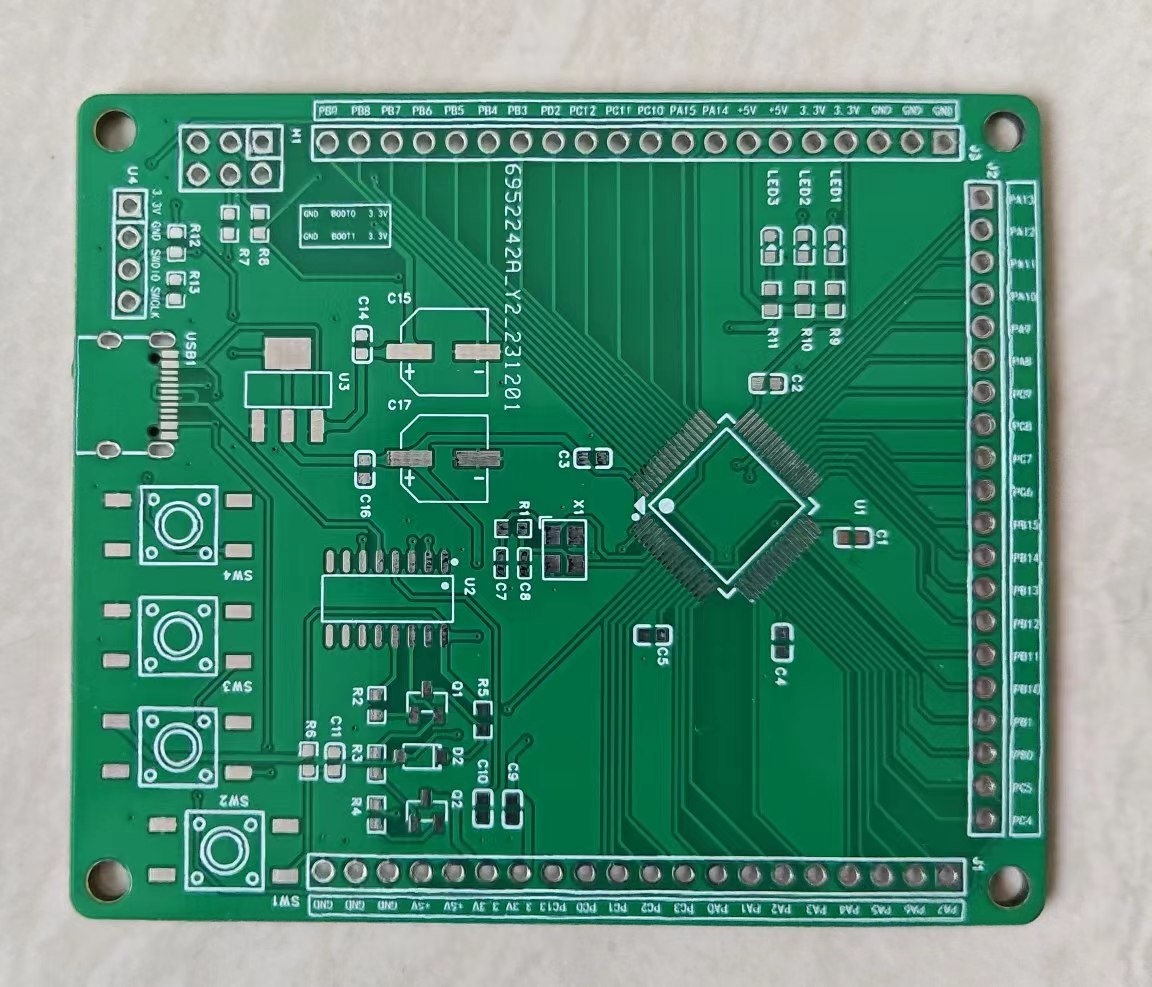
[Development Board Overview]:
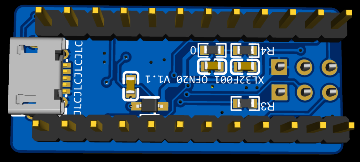
A micro-USB interface is placed on the back of the PCB, used only to provide 5V power, without communication function;
all pins are brought out, with two 12-pin headers on both sides, 400mil spacing, which can be directly inserted into a breadboard;
two WS2812 cascaded 5050 packages are integrated, connected to pin A5, as indicated on the silkscreen;
the 2x3 header on the front is the programming interface, which includes the four standard SWD pins, as well as reset (RST) and serial output (TX);
no LDO is integrated because the microcontroller supports 3~5V power supply, which is more convenient;
the PCB size is 33 x 14.8mm; the function of each pin of
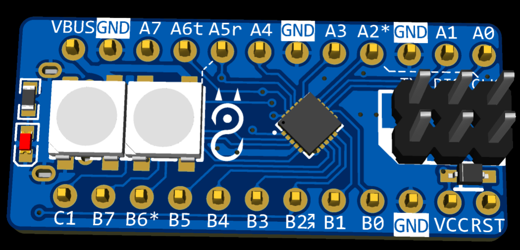
the programming interface
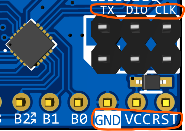
is silkscreened nearby. I made an adapter board to connect the 10-pin JLINK OB programmer. Switching to this interface eliminates the need for a bunch of DuPont wires during programming; simply plug in from both ends, which is very convenient.
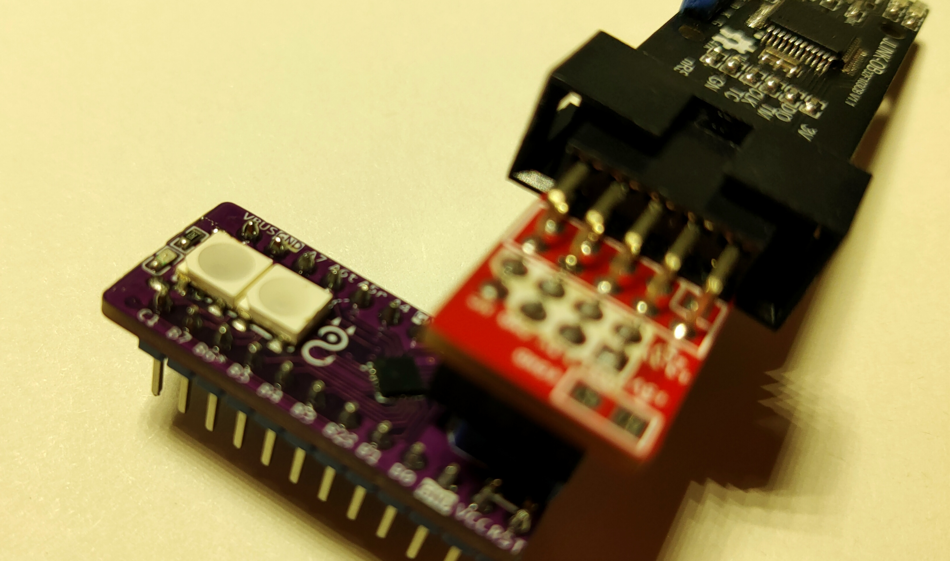
I recommend using the JLINK OB programmer in conjunction with the EIDE development environment. I haven't quite figured out DAP-LINK; OpenOCD is a bit complicated. I wonder if it's plug-and-play with Keil. Several pins have pre-assigned functions on
the silkscreen : A2*: Connected to the CLK pin of the programming interface with a dashed line, indicating this pin is used as SWCLK by default; B6*: Used as SWDIO by default; A5r: Connected to the WS2812's data input pin; 'r' indicates RGB, not RX; A6t: Connected to the TX pin of the programming interface, used as serial output, with the other side corresponding to the programmer's serial port RX; B2: Connected to the ordinary LED next to the WS2812. Note that you can download the LL library and many sample codes for this microcontroller from the official website. The code rarely mentions the name XL32F001; it mostly uses PY32F002B. PS has created an auxiliary table to facilitate the allocation of pin multiplexing functions. The function should be intuitive enough, so I won't go into details. You can download it directly from the attachment.

PDF_XL32F001 Compact Development Board.zip
Altium_XL32F001 Compact Development Board.zip
PADS_XL32F001 Compact Development Board.zip
BOM_XL32F001 Compact Development Board.xlsx
95930
Amateur radio call sign
Currently, this call sign is not yet fully developed due to limited artistic design capabilities. We haven't decided what elements to add next
, but the next step is to incorporate an NFC coil for practical access card applications.
The call sign plate references
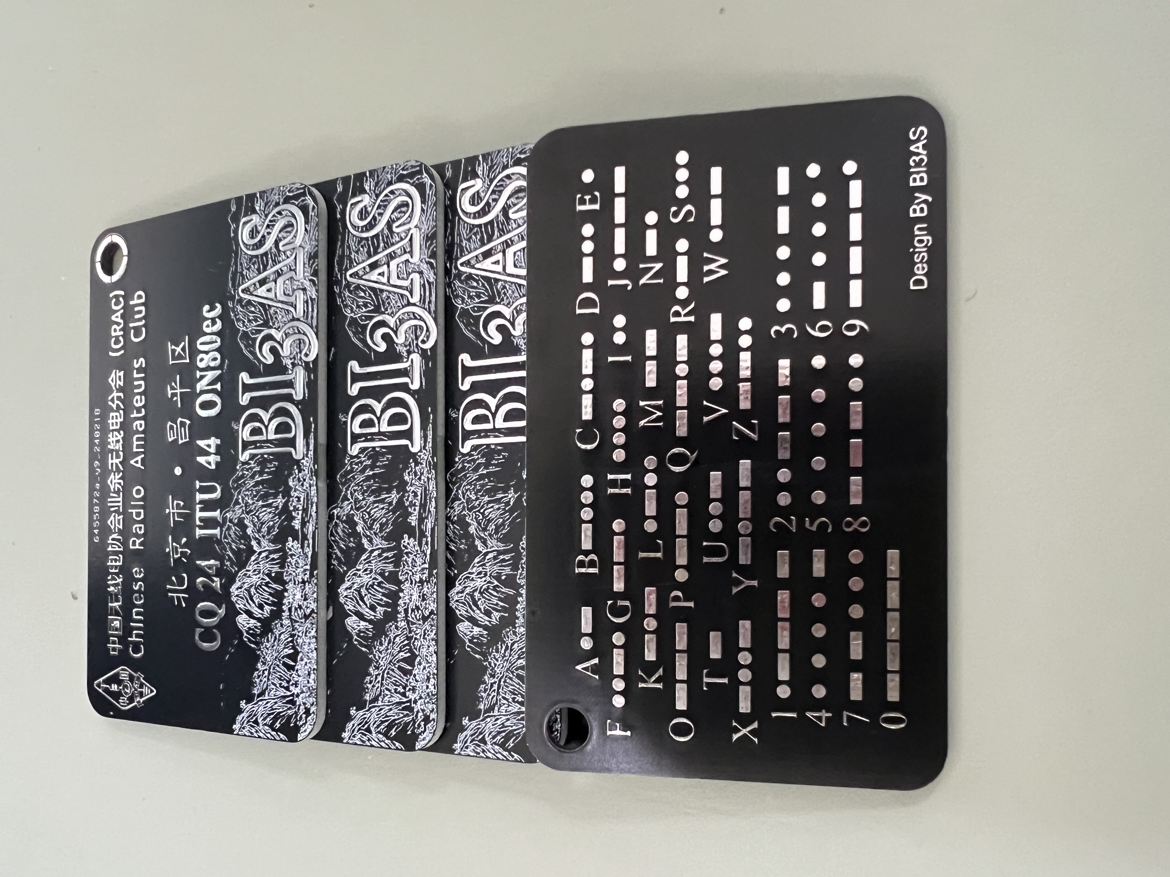
the call sign on the bottom layer of my QSL card, and the Maidenhead network uses the same artistic font as the QSL card, directly inserted as an image and converted
(when changing, it's best to generate the artistic font, convert it to an image, and import it into a specific layer for replacement). The top layer was too plain, so an image was added to the silkscreen layer; I haven't decided what to replace it with yet.
The letters below "China Amateur Radio Association Amateur Radio Branch" and the text below were edited using fonts from the official website, and the effect is similar to the official website. If a more accurate font is found later, I will make precise edits (currently using Founder Zhenghei Simplified and BDP Clien Regular fonts).
Welcome fellow stations to discuss
DE BI3AS!
PDF_Amateur Radio Call Sign Plate.zip
Altium_Amateur Radio Call Sign Plate.zip
PADS_Amateur Radio Call Sign Plate.zip
BOM_Amateur Radio Call Sign Plate.xlsx
95931
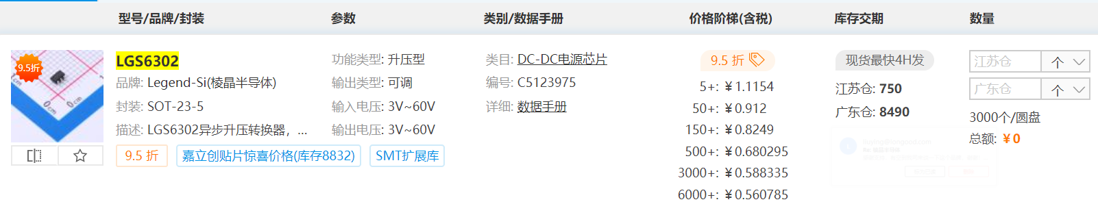
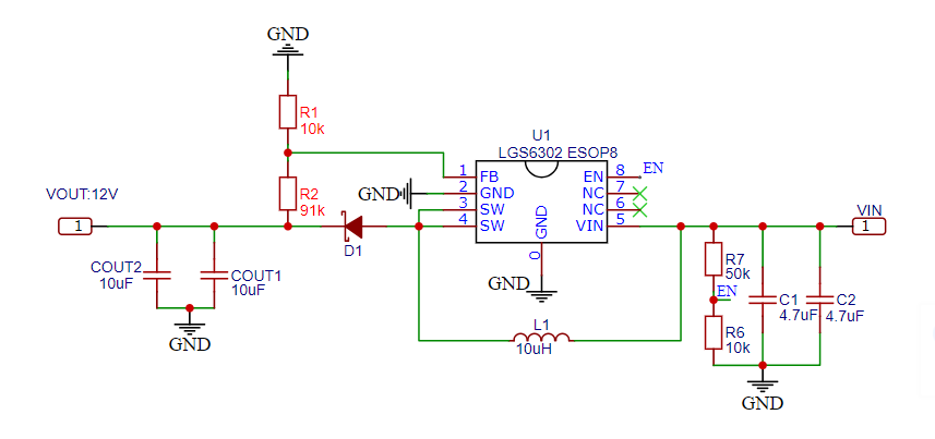
LGS6302 (DC-DC Boost)
Wide input/output voltage range: 3.0V-60V;
up to 90% boost efficiency;
soft start, thermal shutdown, UVLO undervoltage lockout, cycle-by-cycle current limiting protection.
The LGS6302 is an asynchronous boost converter with integrated power switching and a wide input voltage range of 3V to 60V. It integrates soft-start, minimizing the need for external surge suppression components, making it ideal for wide input power range boost converters. The output voltage can be configured using external resistors of varying values.
The LGS6302 output current can be adjusted using an external resistor divider. Recommended output resistor values are shown in the table below. The divider network consists of RG and RF; ensure RG is less than or equal to 30K. The converter regulates the output voltage by maintaining the voltage on the FB pin equal to the internal reference voltage VREF. Once RG is selected, the value of RF can be selected based on VFB, which is typically 1.2V. JLCPCB's reference price : The LGS6302 is available in two different packages; the ESOP8 package offers better heat dissipation, while the SOT23-5 package is more affordable. Schematic Diagram: Testing Section: I then tested some functions and parameters of the LGS6302: Test Conditions: VIN: 5V VOUT: 12V; Io: 500mA Test Conditions: VIN: 12V VOUT: 24V; Io: 500mA Test Environment: Temperature 24℃, Relative Humidity 57% Test Tools: GW Instek 4-channel adjustable DC power supply, Keysight digital multimeter, ITECH IT8811 electronic load, Xinsite thermal imager, Keysight oscilloscope; Sample: You can contact the original manufacturer to apply for a sample. Actual Test Data: Output Voltage: 12V Output Voltage: 24V Maximum Output Current Input Voltage Efficiency Maximum Output Current Input Voltage Efficiency 250mA 3.2V 69.85% 60mA 3.3V 78.56% 330mA 3.7V 74.25% 220mA 5.0V 82.29% 400mA 4.2V 79.14% 420mA 8.4V 87.36% 530mA 5V 81.61% 720mA 12V 90.55% 1000mA 8V 88.39% 1230mA 18V 93.80% Some measured waveforms: In CCM mode, input: 12V, output: 24V, output current: 500mA (ripple test) In CCM mode, input: 5V, output: 12V, output current: 500mA (power-on waveform) Efficiency graph of VIN:5V, VOUT:12V Efficiency graph of VIN:12V, VOUT:24V Overall conclusion: The chip's overall performance is good, and there are no problems with normal use.


Gerber_LGS6302-(DC-DC Boost)_PCB_LGS6302-ESOP8-(Open Source)_2024-02-28.zip
BOM_LGS6302-(DC-DC Boost)_2024-02-28 (1).csv
PCB_PCB_LGS6302-ESOP8-(Open Source)_2024-02-28.json
BOM_LGS6302 (DC-DC Boost).xlsx
95932
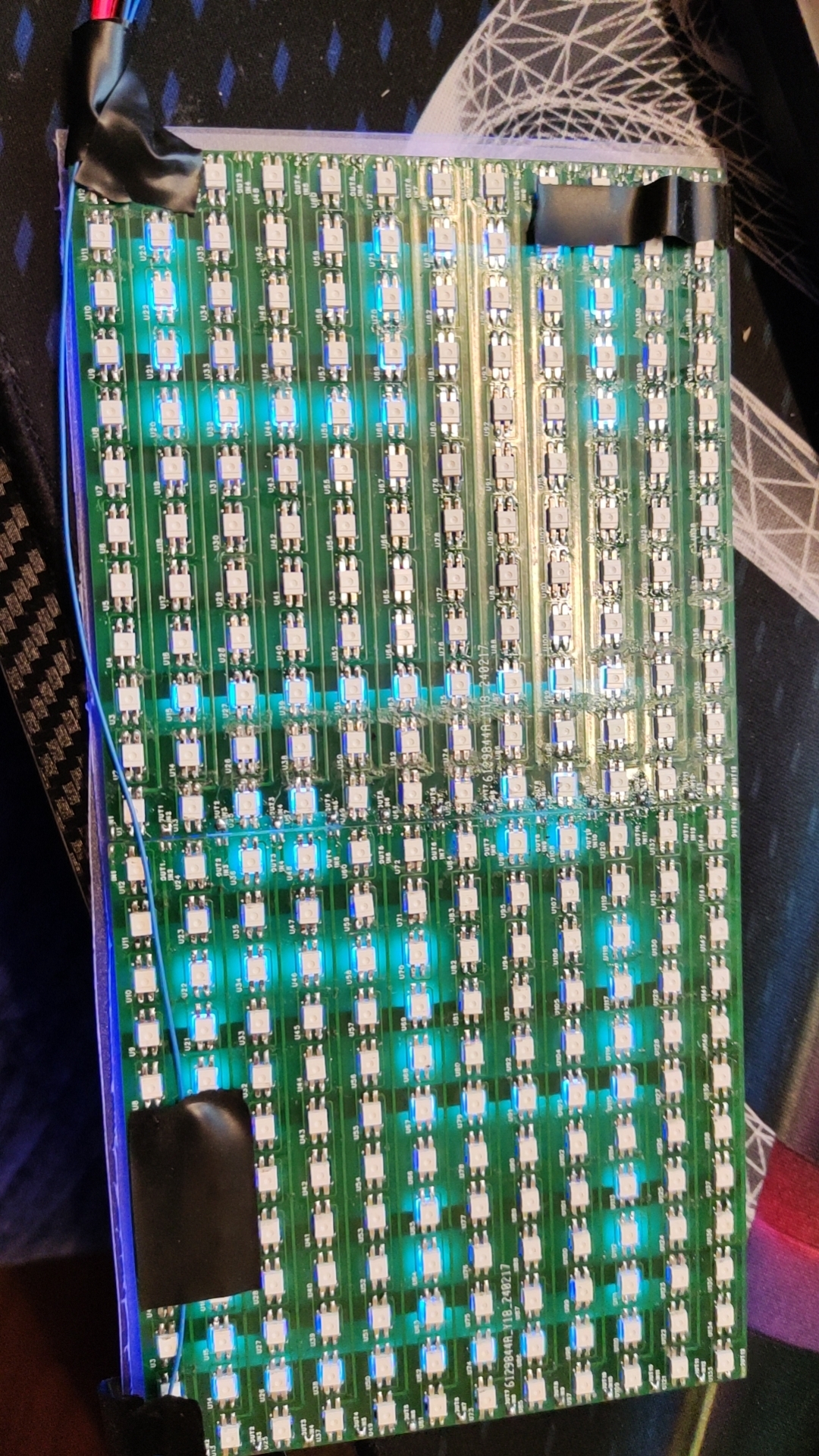
WS2812B dot matrix screen
The WS2812B dot matrix display controls one screen per pin via the ESP8266. Through algorithm optimization, it can simultaneously control multiple screens for coordinated operation.
The clock function implemented using a MicroPython script written with an ESP8266 is attached.

ESP8266---MicroPython program.zip
PDF_WS2812B Dot Matrix Screen.zip
Altium_WS2812B dot matrix screen.zip
PADS_WS2812B dot matrix screen.zip
BOM_WS2812B Dot Matrix Screen.xlsx
95933
220V to 12V transformer power supply
This is actually the second version. Discussions and feedback are welcome. (The only group is 289917684)
This is actually the second version. The previous 12V switch used the same one as the 220V one, but I realized I was using the wrong one when the switch light didn't turn on. I added lights before and after the 12V switch to check for residual power. I also added a circuit that can quickly use up any remaining power after a power outage. I don't have a clear idea yet. The output is actually 18V; I'll add a voltage regulator chip later. Discussion and guidance are welcome. (Only group: 289917684)
PDF_220V--12V Transformer Power Supply.zip
Altium_220V--12V Transformer Power Supply.zip
PADS_220V--12V Transformer Power Supply.zip
BOM_220V--12V Transformer Power Supply.xlsx
95935
Power supply board
The power adapter board covers Python-C, microUSB, DC005-2.5, DC005-2.1, 5.0m terminals and a high-current adjustable LDO.
Don't let its simplicity fool you; you'll regret not having it when you need it. It's incredibly convenient; in almost half the situations, I'm too lazy to even turn on my desktop power supply.
(Includes three personal items)
PDF_Power Supply Board.zip
Altium power board.zip
PADS_Power Supply Board.zip
BOM_Power Supply Board.xlsx
95936
power_board
Adjustable power supply
supports 5-20V input and
0.5-18.5V output;
real-time voltage and current display;
constant voltage or constant current output;
output overcurrent protection;
over-temperature protection;
PD fast charging input.
1. The DC-DC power supply uses a BUCK topology and an STM32G431 as the main controller.
2. The CH224K decoy chip can easily extract up to 20V from chargers or power banks that support PD fast charging.
3. Interaction is achieved via an LCD screen and rotary encoder. The LCD homepage displays the target voltage, current, switch status, actual output voltage, current, and power. A long press enters the menu settings page, where the PD-induced voltage can be adjusted, and voltage, current, and temperature calibration and viewing functions can be performed. A power statistics function can be added later.
4. When the actual current is less than the target current, it is in constant voltage output mode, and the constant current indicator is off. When the actual current is greater than the target current, it is in constant current mode, with the constant current value being the target current value, and the constant current indicator is on. This mode is very convenient for charging batteries.
See the demonstration video on Bilibili: BV1zr421p7jG
Demo video.txt
PDF_power_board.zip
Altium_power_board.zip
PADS_power_board.zip
BOM_power_board.xlsx
95938
Hikvision 4117 thermal imaging modification
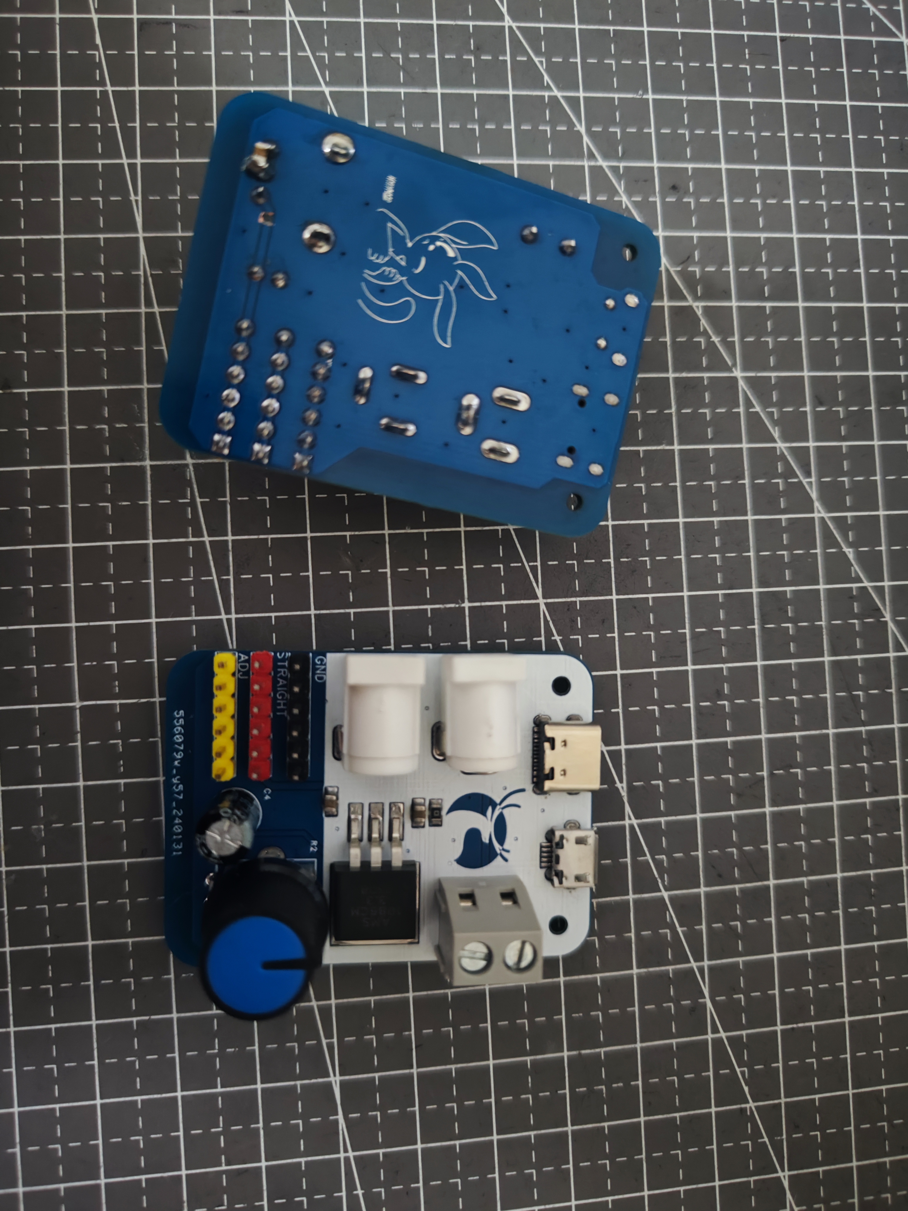
Hikvision 4117 adapter board
The BOM (Bill of Materials) is just one component on the adapter board. Other required components include:
a 15*15*1.5mm copper heatsink
, a 0.5mm silicone thermal pad (can be cut to size or 15*15mm is fine)
, M1.4*2.5*2.3mm hot-melt knurled nuts, and
M1.4*4mm flathead Phillips screws.
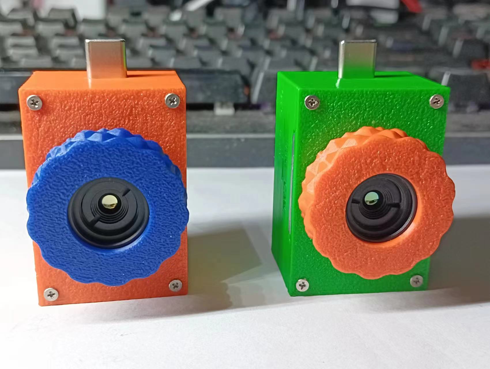
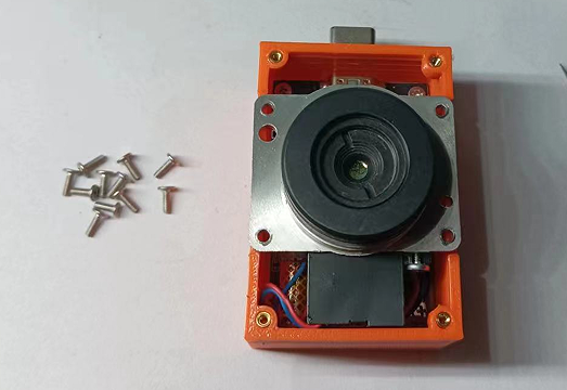
Let's first discuss the features: the back is open, let's call it the "Exploration Edition" for now. It has two USB-C ports, one male and one female, for connecting to a phone or a computer (only one can be connected at a time, not both simultaneously). It has a parameter adjustment switch, allowing you to adjust parameters directly without disassembling the casing. The focus ring is knurled, providing a very good feel.
Precautions:
1. Due to the open back, be careful to prevent water and dust damage.
2. Only one USB port can be connected at a time.
3. Adjust the switch when the power is off; do not move it when the power is on. (Later I found that the OTG and USB switches were basically useless, but I was too lazy to change them.)
4. When the switch is set to CAM or OTG, it can connect to either a computer or a phone; when set to USB, it can only connect to a computer. When the switch is set to DUG, it enters parameter tuning mode, requiring an external network card.

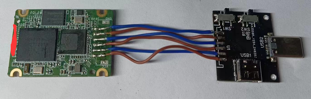
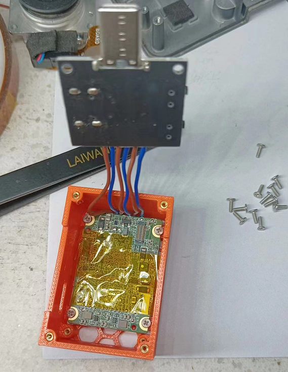
I won't go into detail about disassembling the module; solder the adapter board. The wires are pin-to-pin; just solder them parallel to each other, as shown in the picture .
Note that you shouldn't use wires that are too thick, otherwise they won't fit. After
attaching the heatsink

and soldering, cover the front of the board with a layer of tape to prevent the components above from being knocked off during installation (don't ask me why I'm reminding you) .

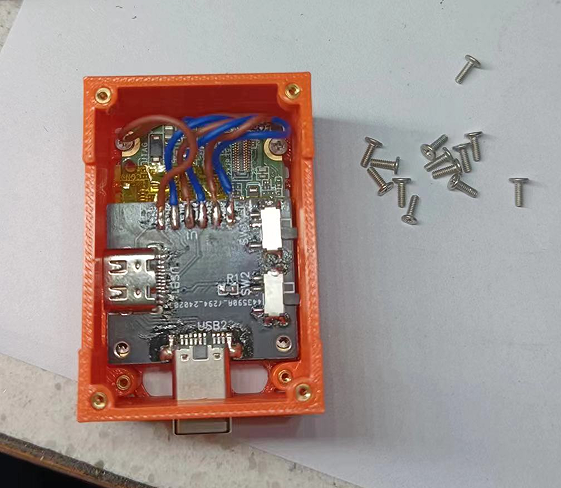
Clean off the supports
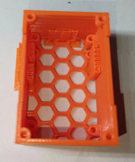
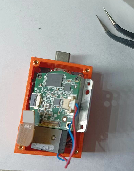
and then put on the knurled nuts. Install the motherboard
and then install the adapter board on top. This step requires some patience; be careful not to damage the components below, which is why you use tape.
The rest is simple: install the ribbon cable. Note that there are two layers of foam at the shutter switch on the camera; remove them.
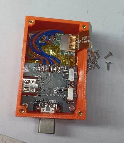
Put the cover on and screw it in.
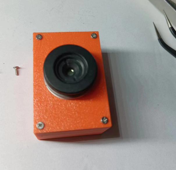
Use a utility knife to remove the adhesive from the lens, cleaning both sides until you can screw the lens in.

Screw on the lens cap, and enjoy!

cb472fba3bc2bfc0f1ff28b6b9b097eb.mp4
Lens cap.step
Thermal imaging substrate.step
Thermal Imaging Cover.step
4117 Thermal Imaging Assembly.pdf
PDF_Hikvision 4117 Thermal Imaging Modification.zip
Altium_Hikvision4117 thermal imaging modification.zip
PADS_Hikvision 4117 Thermal Imaging Modification.zip
BOM_Hikvision 4117 Thermal Imaging Retrofit.xlsx
95939
electronic


 京公网安备 11010802033920号

 15KW48CACOX.200


