Multi-head converter


PDF Multi-Head Converter.zip
Altium Multi-Head Converter.zip
PADS_Multi-head Converter.zip
BOM_Multi-head Converter.xlsx
96208
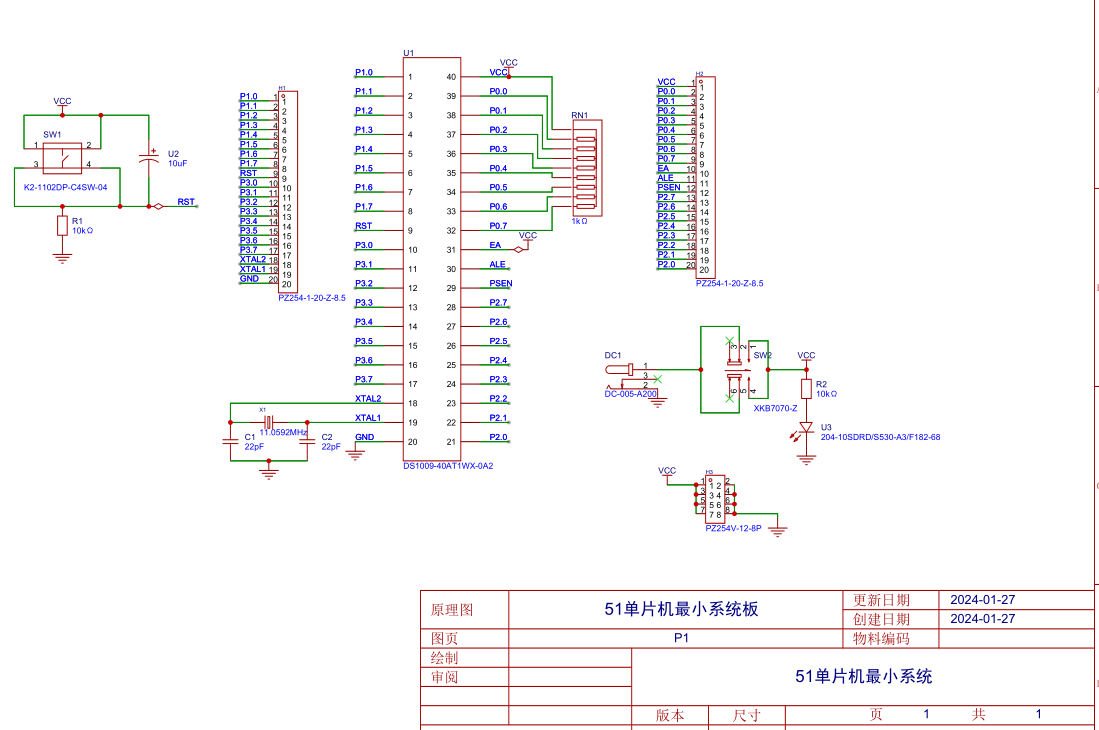
51 microcontroller minimum system
A microcontroller minimum system refers to a system that can function using a microcontroller with the fewest possible components. For the 51 series microcontrollers, the minimum system typically includes the microcontroller chip, a crystal oscillator circuit, and a reset circuit.
1.
Reset Circuit
Purpose: The reset circuit of a microcontroller is similar to the restart function of a computer. When a computer freezes during use, pressing the restart button restarts the internal program from the beginning.
Similarly, when a microcontroller system malfunctions due to environmental interference, pressing the reset button automatically restarts the internal program.
Working Principle: In a microcontroller system, the system resets once upon power-on. Pressing the button resets the system again, and releasing and then pressing it again will reset the system once more. Therefore, the reset can be controlled by opening and closing the button during operation.
Power-on Reset: In the circuit diagram, the capacitor is 10uF and the resistor is 10kΩ. According to the formula, the time required for the capacitor to charge to 0.7 times the power supply voltage (the microcontroller's power supply is 5V, so 0.7 times is 3.5V) is 10kΩ * 10uF = 0.1s.
That is, within 0.1s of the microcontroller's startup, the voltage across the capacitor increases from 0V to 3.5V. At this point, the voltage across the 10K resistor decreases from 5V to 1.5V (the sum of voltages across the series circuit is the total voltage).
In the 51 microcontroller, a voltage signal less than 1.5V is a low-level signal, while a voltage signal greater than 1.5V is a high-level signal. Therefore, within 0.1 seconds of power-on, the microcontroller system automatically resets (the high-level signal received by the RST pin lasts approximately 0.1 seconds).
Button reset: 0.1 seconds after the microcontroller starts up, the voltage across the capacitor continues to charge. At this time, the voltage across the 10K resistor is close to 0V, and RST is at a low level, so the system works normally.
When the button is pressed, the switch is turned on, and a circuit is formed across the capacitor, short-circuiting it and allowing it to release the previously charged charge.
Over time, the capacitor voltage drops from 5V to 1.5V, or even lower, within 0.1 seconds.
According to the principle that the voltage across the series circuit is the sum of voltages across the series circuit, the voltage across the 10K resistor is 3.5V, or even higher, at which point the RST pin receives a high level again, and the microcontroller system automatically resets.
2.
Crystal Oscillator Circuit: The crystal
oscillator provides the operating signal pulses to the microcontroller, which determine the microcontroller's operating speed. For example, a 12MHz crystal oscillator means the microcontroller operates at 12MHz per second.
The oscillation circuit formed by the crystal oscillator and the microcontroller's XTAL0 and XTAL1 pins generates harmonics. While these harmonics have a minor impact on the overall circuit, they can reduce the stability of the clock oscillator.
To improve circuit stability, Atmel (the manufacturer of the 89C51 series) recommends connecting two 10pF-50pF ceramic capacitors to the two pins of the crystal oscillator and grounding them to reduce the impact of harmonics on circuit stability. Therefore, the capacitors in the crystal oscillator circuit can be between 10pF and 50pF.
3.
Pull-up
Resistors for Port P0: When Port P0 is used as an I/O port output, a low output level is 0, and a high output level is a high configuration (not 5V, equivalent to a floating state). This means Port P0 cannot truly output a high level to provide current to the connected load. Therefore, a pull-up resistor (a resistor connected to VCC) must be connected, and the power supply provides current to the load through this pull-up resistor.
Since Port P0 does not have an internal pull-up resistor and is open-drain, regardless of its driving capability, it is essentially without power and requires external circuitry to provide it. In most cases, a pull-up resistor must be added to Port P0.
Precautions for using Port P0:
1. Generally, when Port P0 of a 51 microcontroller is used for address/data multiplexing, a pull-up resistor is not required.
2. When used as a general I/O port, a pull-up resistor must be connected because it lacks an internal pull-up resistor.
3. When Port P0 is used to drive a PNP transistor, a pull-up resistor is not required.
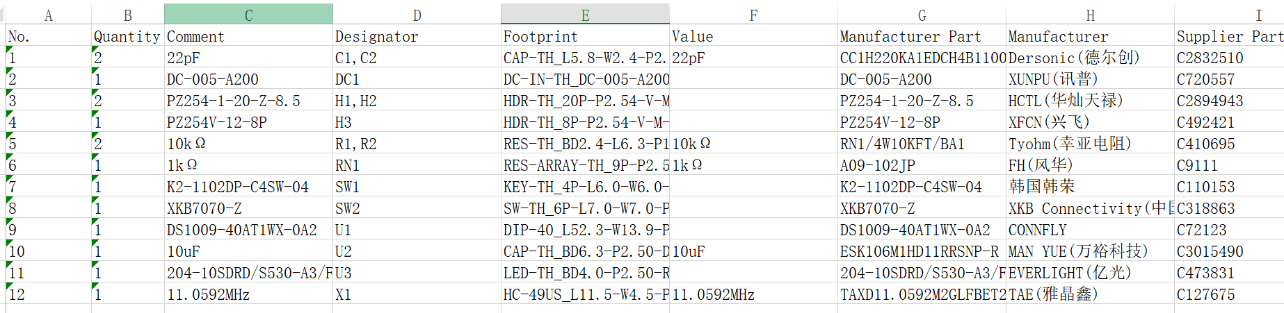
BOM_Board1_51 Microcontroller Minimum System Board_2024-01-27.xlsx
SCH_51 Microcontroller Minimum System Board_2024-01-27.pdf
PDF_51 Microcontroller Minimum System.zip
Altium_51 Microcontroller Minimum System.zip
PADS_51 Microcontroller Minimum System.zip
96210
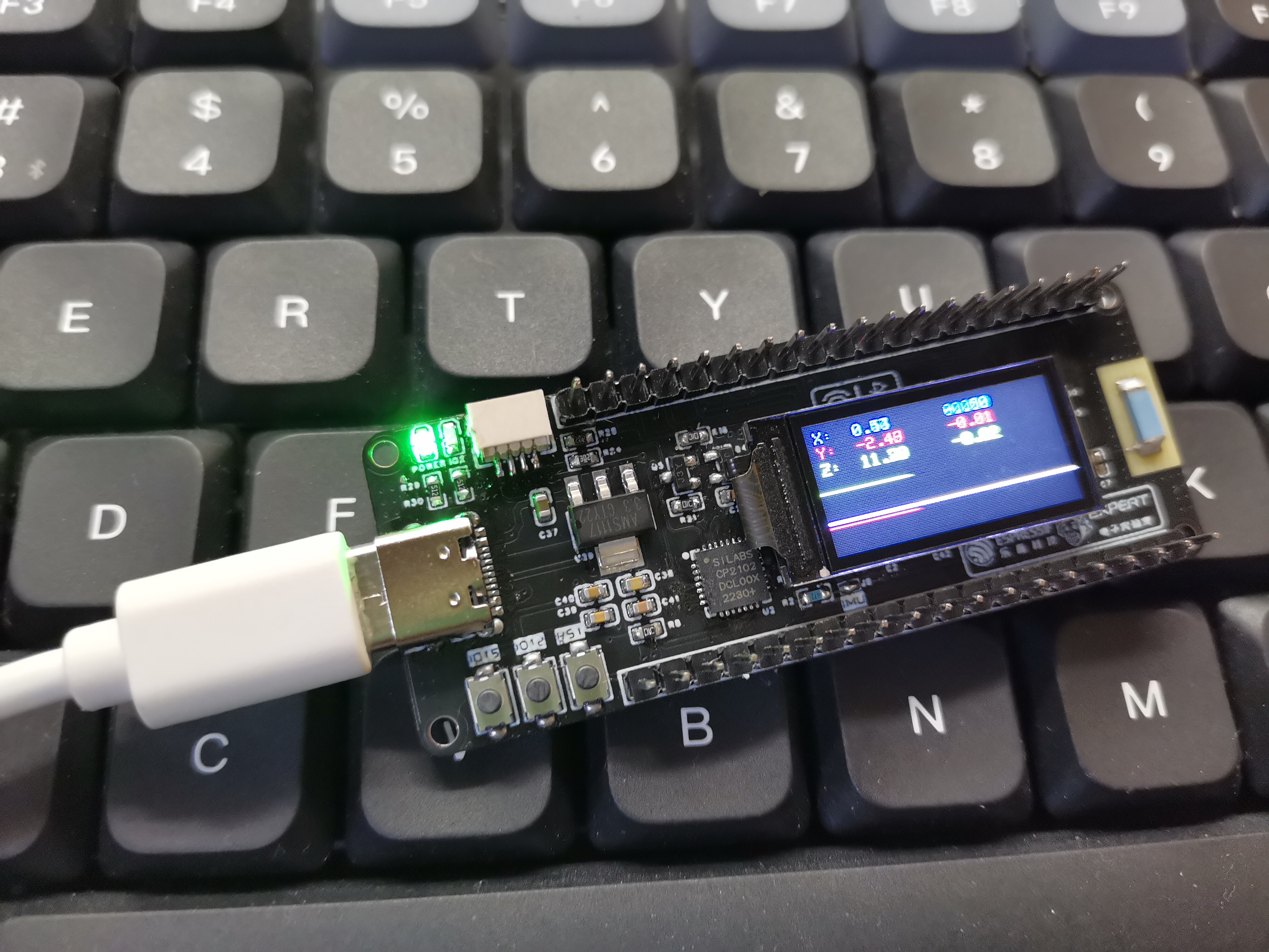
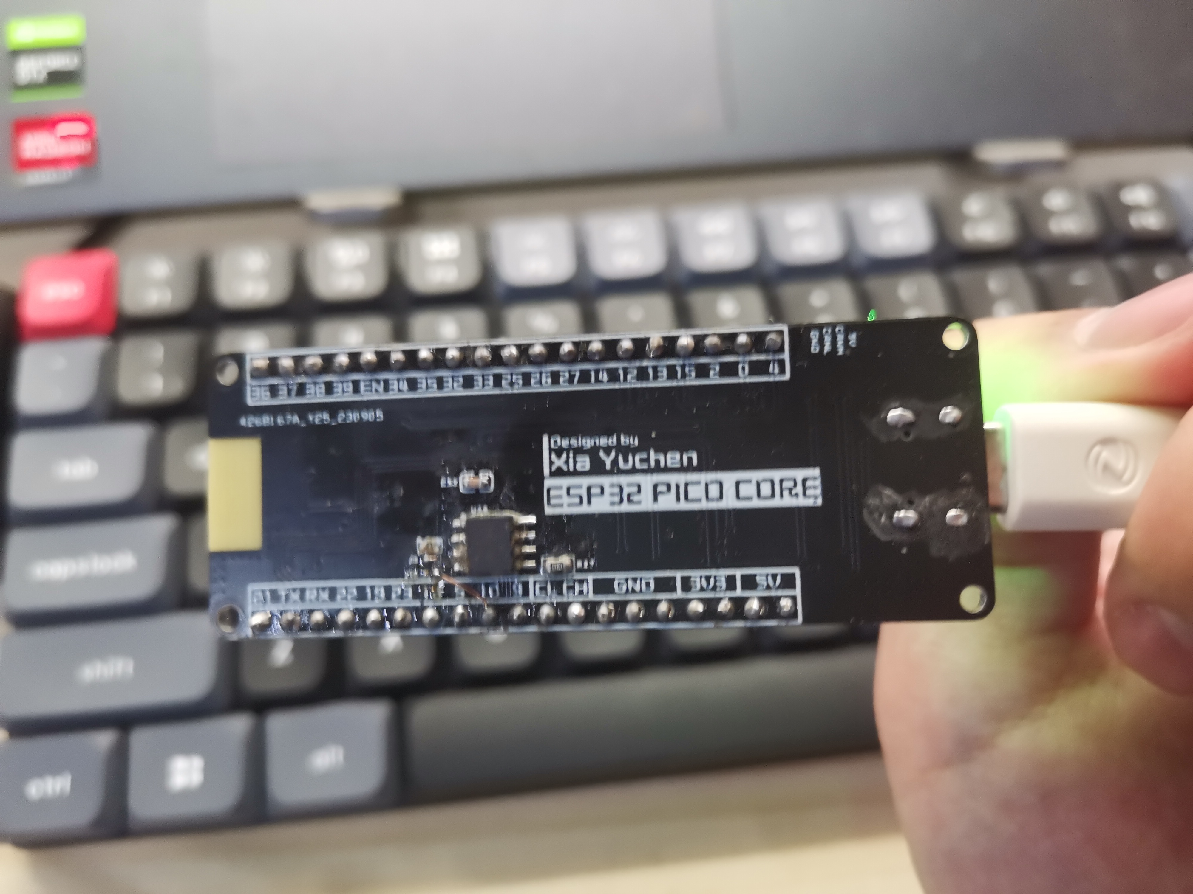
ESP32 core board with screen gyroscope CAN interface
ESP32 core board with screen, gyroscope, and CAN interface -
same core board design as Zhihui Jun.
ESP32 core board with screen, gyroscope, and CAN interface. Same core board design as Zhihui Jun.
Onboard resources:
TFT screen
CAN protocol conversion chip,
MPU6050, and all
button pins are brought out.

ESP32PICO.zip
PDF_ESP32 core board with screen, gyroscope, and CAN interface.zip
Altium_ESP32 core board with screen, gyroscope, and CAN interface. zip
PADS_ESP32 core board with screen, gyroscope, and CAN interface. zip
BOM_ESP32 core board with screen, gyroscope, and CAN interface.xlsx
96211
stm32_arduboy_V1.0 game console
This is a game console based on STM32F103C8T6. The software is based on Arduboy2 and is currently in its first version. It is basically working and can run some games.
This is a gaming console based on the STM32F103C8T6 motherboard. The software is a modified version of Arduboy2, currently in its first version. It's basically working and can run some games.
It's not Arduino; it uses native code . For
an introduction and video tutorial, see: [stm32_arduboy_V1.0 Gaming Console - Introduction].
I'm a newbie, just messing around with it, so please give me suggestions. I'll continue to optimize and add new games later. The display experience in this version isn't great; I don't recommend copying it exactly. Switching to an SSD1306 OLED might improve things;
I've already tested it, and the effect is excellent with an SSD1306. This is the current version; I'll improve it in future versions.
Currently running demos/games (may have bugs):
BeepDemo,
Buttons,
FontDemo,
HelloWorld,
PlayTune,
RGBled,
SetSystemEEPROM,
ArduBreakout ,
rund,
halloweend,
ID-34-Mystic-Balloon,
ShadowRunner
, Arduboy3D,
ardynia,
CastleBoy.
FlappyBall
finished product display
: Front (actually the bottom of the PCB):
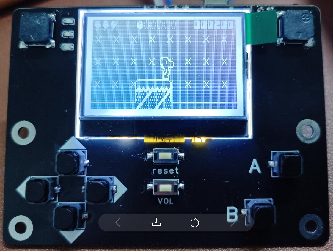
Back (actually the top of the PCB):

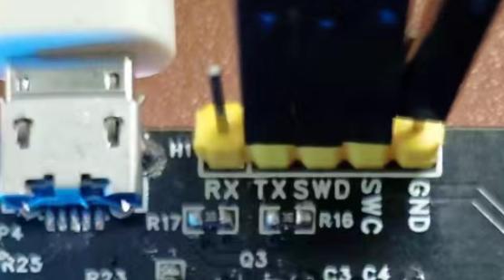
Currently in the debugging stage, the battery is not installed, and it is powered by USB. The jumper cap needs to be adjusted to USB power. The schematic shows that
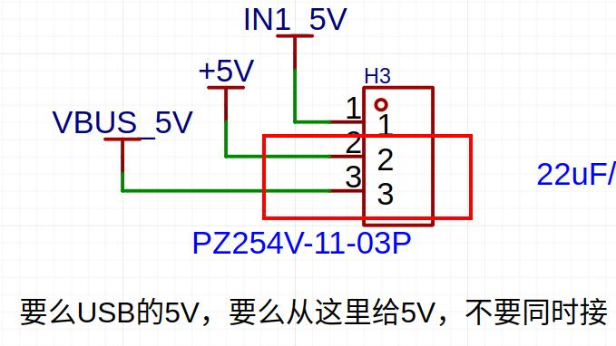

debugging and code burning require connecting the debugging header with a JLINK. Do not solder this header if you are not debugging, as shown in the image below.
Software source code repository:
The software code will be open-sourced at the following location: https://gitee.com/lambda_zhang/arduboy2_stm32
Current version issues:
The LCD uses an ST7567, which displays obvious ghosting. This will be replaced in the next version.
Buzzer code not yet debugged.
Battery not yet tested.
USB not yet tested.
E2PROM and Flash not yet tested.
Hardware explanation:
Why use STM32F103C8T6? Because I happened to have one on hand, and the STM32F103C8T6 is quite cheap and easy to solder. However, Arduboy2 could not find a version that runs on STM32, so the software had to be ported myself.
Why are there two buzzers? The code shows two LEDs, but the sound code isn't finalized yet.
Why are there three LEDs? Also, the code shows three.
Why is there one E2PROM and one Flash? The E2PROM is from the code, and the Flash is something I added because others have it, although it's not used yet. Later, we might not need the E2PROM and only need the shared Flash.
Why is there a 'reset' and a 'VOL'? 'Reset' is the microcontroller's reset, and 'VOL' is used to switch the sound on/off. The 'VOL' code isn't developed yet.
Why use an ST7567 LCD instead of the SSD1306 from the code? Because I happen to have several ST7567 LCDs on hand.
Why is the board so large? Others make them smaller. Because I have a large battery, and I made
the circuitry based on the battery size. Is each part of the circuit reliable? I'm not a hardware engineer; I copied the circuits from various websites, and I don't know anything about wiring rules. I just assume everything is connected correctly
. How did I do the soldering?
Why not use a Type-C USB port when I bought solder paste and a heating plate to manually build it ? My skills aren't good enough; I feel I can't solder it properly, so I chose
something simpler. Regarding the
STM32F103 development environment, I only have an Ubuntu environment; I don't know how to use Windows. The required development environment is:
Ubuntu version of STM32CubeMX
, gcc-arm-none-eabi-10.3-2021.10,
OpenOCD + JLINK,
VSCODE.
Arduboy2 is based on Arduino; why didn't I use it? Because I don't know Arduino, and learning it would take time (and I'm lazy). I simply ported a gcc + Makefile version myself.
The software project is based on the Makefile project generated by STM32CubeMX. Why not use other environments? I still don't know anything else; I only know gcc + Makefile.
What modifications are needed to port from Arduino? I compiled directly and then resolved the errors.
What modifications are needed for game porting? I found source code online, which also compiled directly and then resolved the errors.
Does it support storing many games in flash memory and selecting which one to run? Currently not supported, will be addressed later when time permits. Currently, it's compiled and then burned into the microcontroller. Changing the game requires re-burning.
Cost calculations:
LCD (10 units including shipping, 22 RMB)
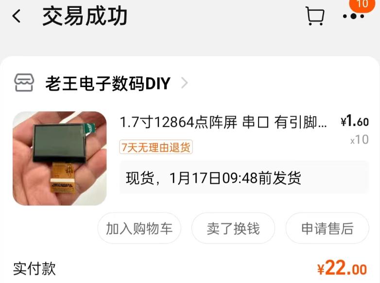
; PCB (6 pieces, 20 RMB);

other components including shipping, 60.96 RMB.
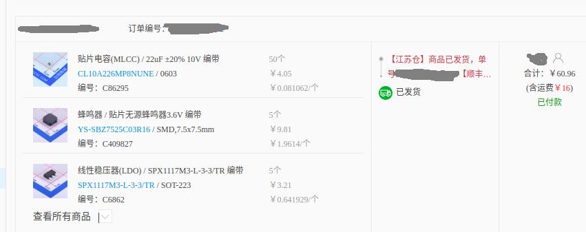
The STM32 is leftover from before, and some resistors and capacitors are also from before
. Summary: This is a bit unclear, so I'll leave it at that...
Also, buying components from LCSC Mall gave me this error message!!

game1.mp4
output2.mp4
PDF_stm32_arduboy_V1.0 game console.zip
Altium_stm32_arduboy_V1.0 game console.zip
PADS_stm32_arduboy_V1.0 game console.zip
BOM_stm32_arduboy_V1.0 game console.xlsx
96212
USB-Can
This USB-CAN debugging tool is a replica of the CANable open-source hardware and software project. It supports direct flashing of firmware for SLCAN, PCAN, and Candlelight, and also includes download and serial port interfaces, allowing for custom software development.
The CANable open-source hardware and software project provides a fully open-source USB-CAN debugger
with support for both Windows and Linux stock CANs (driverless) and Python. For details, please refer to the following two links: [

Link 1: canable.io](link 2:
canable.io ) [Link 3:
Zhihu](link 4: Zhihu) Regarding firmware
and host computer support,
this debugger can be programmed using the DfuSeDemo software in DFU mode, but this method is cumbersome. It is recommended to use the online programming website provided by the CANable official website. Currently, it supports SLCAN, PCAN, and Candlelight firmware. For programming methods, please refer to the link above. For the three official firmwares, SLCAN supports the cangaroo host computer, PCAN supports PCAN View, BUSMASTER, and TSMASTER host computers, and Candlelight supports cangaroo, BUSMASTER, and TSMASTER host computers. [Link 5 : Custom Host Computer
Support] Additionally, some firmware also supports Python-CAN control. After practical testing and verification, after flashing the SLCAN firmware and connecting the debugger to the computer, it will appear as a regular serial port device (e.g., COM5 serial device) in the Device Manager. The Python-Can library can be used to control the debugger to send and receive messages. Currently, the serial library has been used to search for serial port devices, and the python-can library has been used to control the CAN debugger. Combined with PyQT for interface design, a self-made host computer system that meets actual work requirements has been completed and is functioning normally. Other notes: 1. The hardware schematic is basically the same as the open-source hardware in CANable, but the PCB has been redrawn; 2. It uses a Micro USB port to connect to the PC, with three LEDs provided for software development. A pin header is used for DFU mode switching and matching resistor switching; 3. Both the USB and CAN interfaces have TVS diodes; these can be removed if not needed; 4. All components except the MCU were purchased from LCSC. The MCU was purchased from Taobao, costing approximately 10-12 RMB per unit; 5. After debugging, you can cover the PCB with heat shrink tubing with an inner diameter of about 15mm (for a better appearance); 6. The current silkscreen is a bit small; you can adjust it yourself; 7. Attachment 1: Cangaroo host computer; 8. Attachment 2: Drivers required for online programming via web page;

cangaroo.zip
ImpulseRC_Driver_Fixer.exe
PDF_USB-Can.zip
Altium_USB-Can.zip
PADS_USB-Can.zip
BOM_USB-Can.xlsx
96213
ESP8266 Downloader
This is a downloader for ESP8266 01/01s/12x. I've been working with WLEED LED strips recently, so I've prototyped this downloader.
This is a clone of https://oshwhub.com/luoxing/esp8266-shao-lu-qi
. 1. I had a leftover CH340G from a few years ago, and I added a crystal oscillator circuit. It works with both CH340C and CH340G.
2. Since it's a clone, I didn't bother changing the original resistors and capacitors; they're in 0805 packages, so I just used 0603 capacitors.
3. I added TX/RX indicator lights, which can be soldered with different colored LEDs as needed. I also replaced two buttons with better-looking tactile switches (which I actually had on hand).
4. Compared to the original open-source address, all the added components are in 0603 packages.
5. The SIM card ejector pins are #000, 18mm, available on Taobao and Pinduoduo, usually a few yuan for 100.
PDF_esp8266 downloader.zip
Altium_esp8266 downloader.zip
PADS_esp8266 downloader.zip
BOM_esp8266 downloader.xlsx
96214
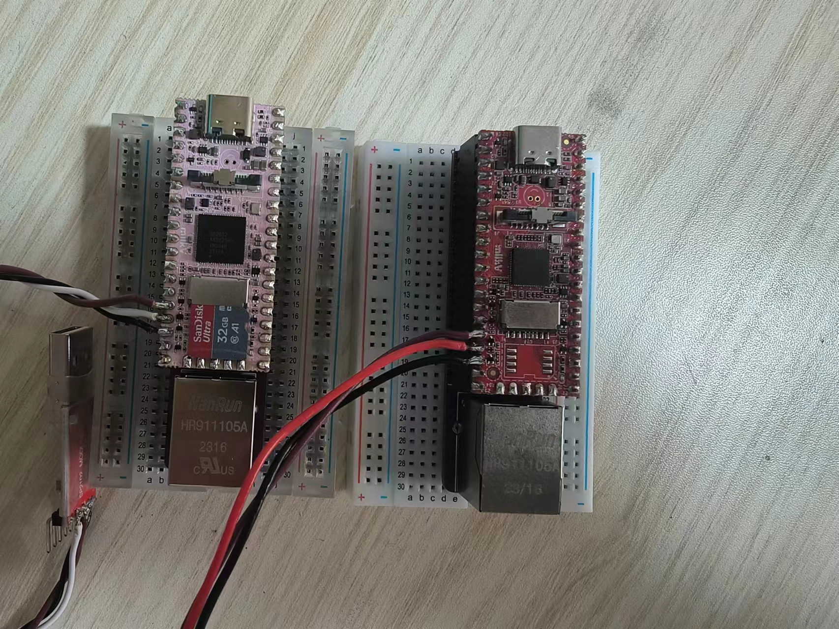
Milk-V duo/256M Mini baseplate
Milk-v duo/256M base plate
The Milk-V Duo/256M features a mini base plate, making it convenient to use on a breadboard.
MilkV1_20240129101131.jpg
MilkV3_20240129101217.jpg
PDF_Milk-V duo-256M Mini baseplate.zip
Altium_Milk-V duo_256M Mini baseplate.zip
PADS_Milk-V duo_256M Mini baseplate.zip
BOM_Milk-V duo_256M Mini baseplate.xlsx
96215
Taishanpai serial port expansion board + casing
It features 5 serial ports, an RPLIDAR communication interface, and a circuit IIC.
The casing is made using 3D printing and CNC machining, while also considering heat dissipation and portability (this model is applicable to JLCPCB's one-yuan CNC rules).
Serial port 3 and the RPLIDAR communication interface are shared.
If you want to enable these serial ports (Linux), please enable them in the device tree of the source code.
The I2C2 interface and
UART are UART3, UART4, UART5, UART7, and UART9.
The LED colors and I/O ports correspond as follows:
GPIO3_A1-B ,
GPIO3_A2-G,
GPIO3_A3-R.
The buttons (numbered 321 from left to right) correspond to the following I/O ports:
GPIO0_B7-SW3,
GPIO3_B3-SW2,
GPIO3_B4-SW1.
IMG20240126111642.jpg
IMG20240126111652.jpg
Taishanpai Shell.zip
PDF_Taishanpai Serial Port Expansion Board + Shell.zip
Altium_Taishanpai Serial Port Expansion Board + Shell.zip
PADS_Taishanpai Serial Port Expansion Board + Shell.zip
BOM_Taishanpai Serial Port Expansion Board + Shell.xlsx
96216
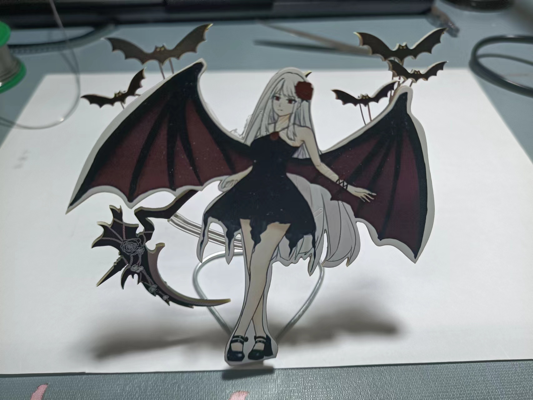
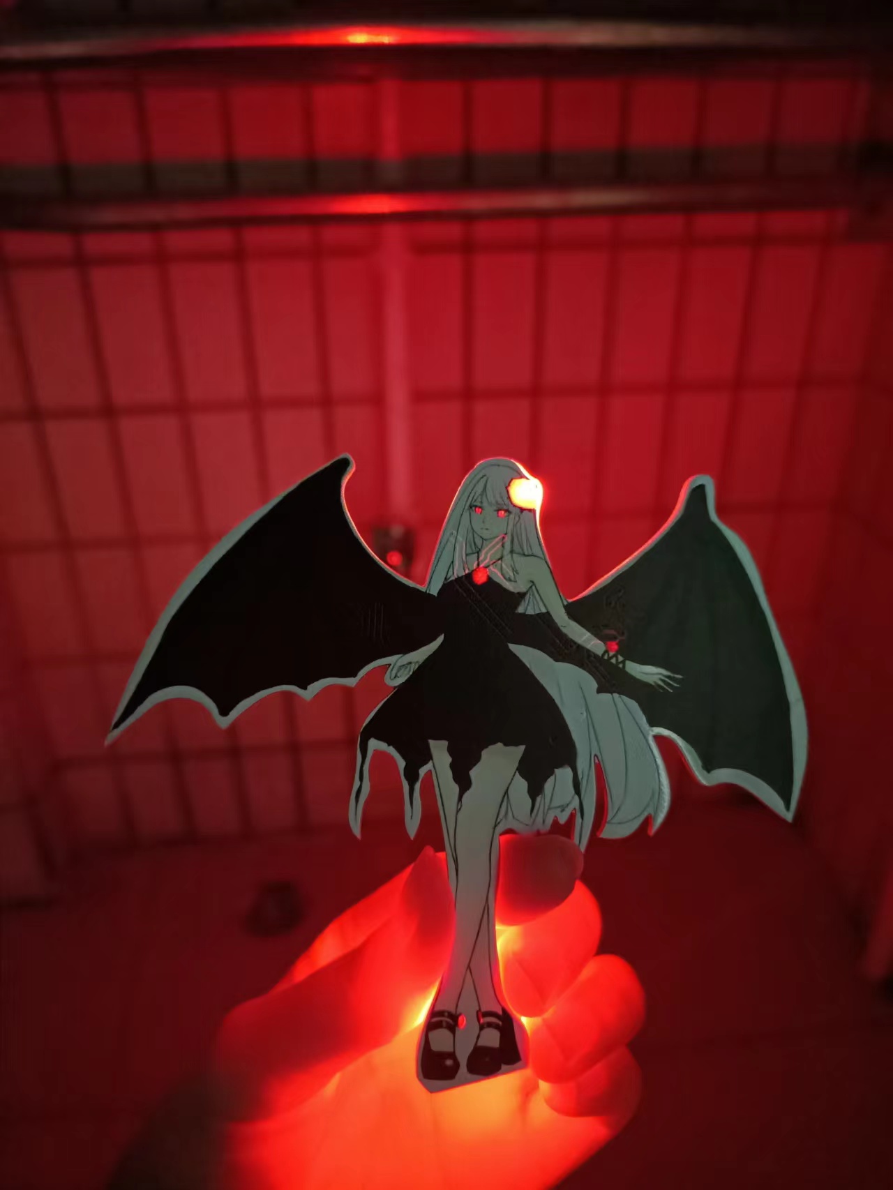
Vampire_rose
This is a colorful silkscreen print featuring a vampire that glows.
This is my first color silkscreen printing project. I saw an event that offered color silkscreen printing, so I drew a white-haired character and put it on (do not use without authorization, please cite the source if you use it, I am the artist). The inspiration is Della Camellia.
Vampire Rose - Vampire, PCB Showcase [Color Silkscreen Printing] _bilibili_bilibili.
However, this wasn't very successful. I'm not very good at circuits, so it's a bit rough. Even simple assembly isn't enough. I used JLCPCB's simulation, but the result seems different from what I imagined. Oh well, I was mainly aiming for the aesthetics. It would be great if an expert could point out the circuit errors. My original idea was for the bat's eyes to flash alternately, slowly like a breathing light, while the other parts remained constantly lit. I just drew
the board outline in CAD and imported it. There were a lot of minor hiccups during the process because I wasn't very good at it, but it finally lit up. However, after soldering on the double flash, it stopped lighting up, I don't know why.
Below is the demonstration image:
PDF_Vampire_rose.zip
Altium_Vampire_rose.zip
PADS_Vampire_rose.zip
BOM_Vampire_rose.xlsx
96217
electronic


 京公网安备 11010802033920号

 M55342M01B110BPT1


