


 III. Functional Modules
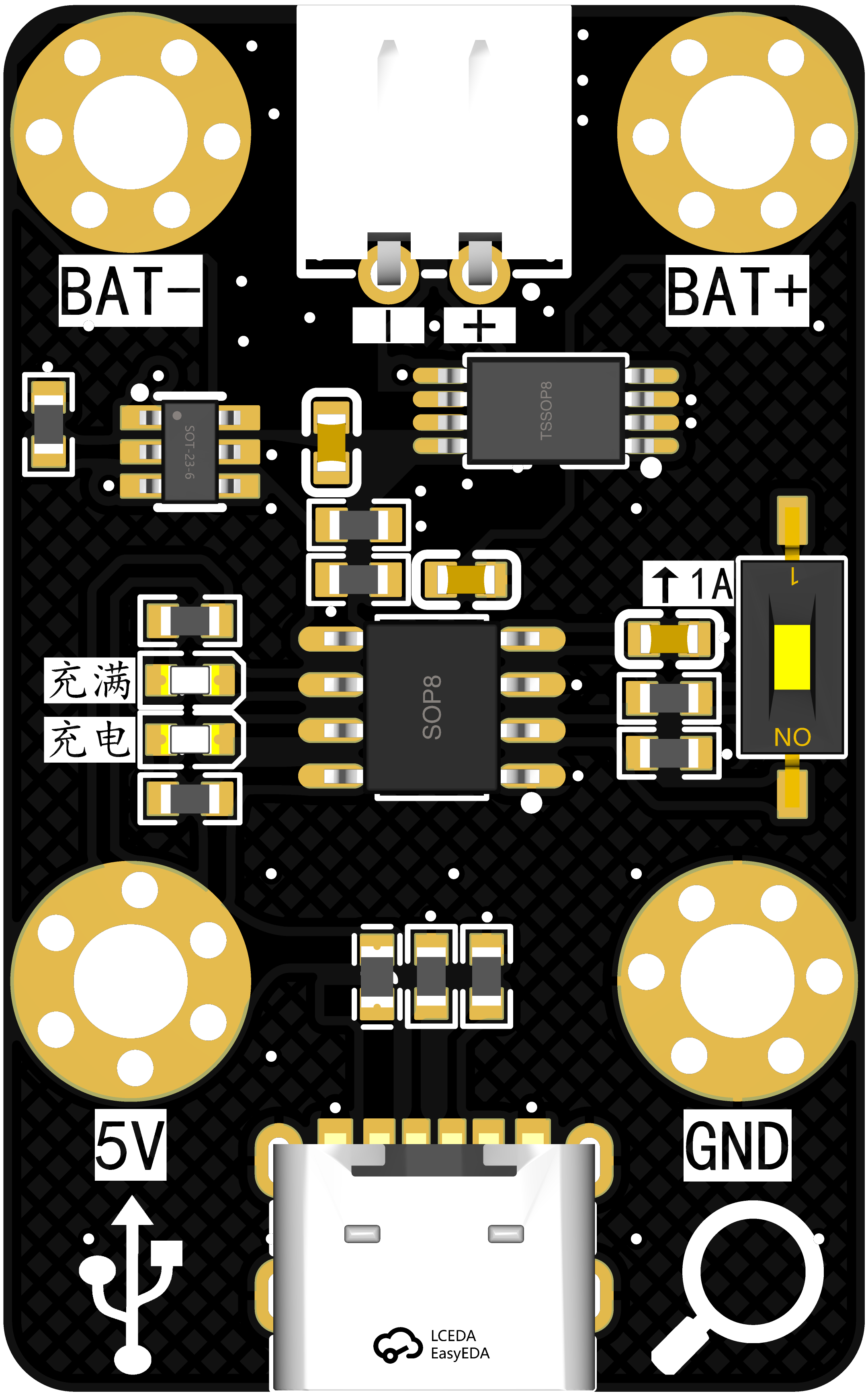
 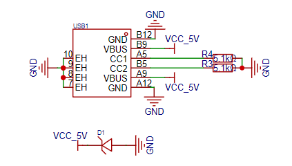 Charging uses a common 6P USB interface, a standard design, which requires no further explanation. D1 is an anti-static diode.
 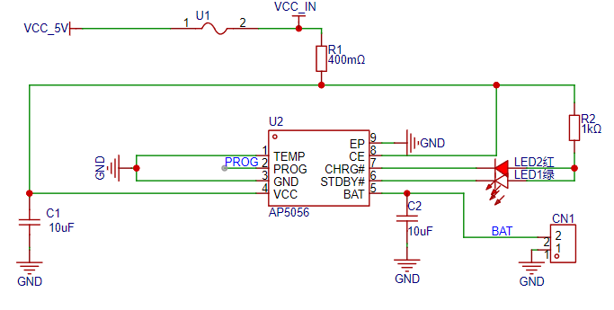 uses the AP5056 charging chip, which is also used on the 01-RTC main control board
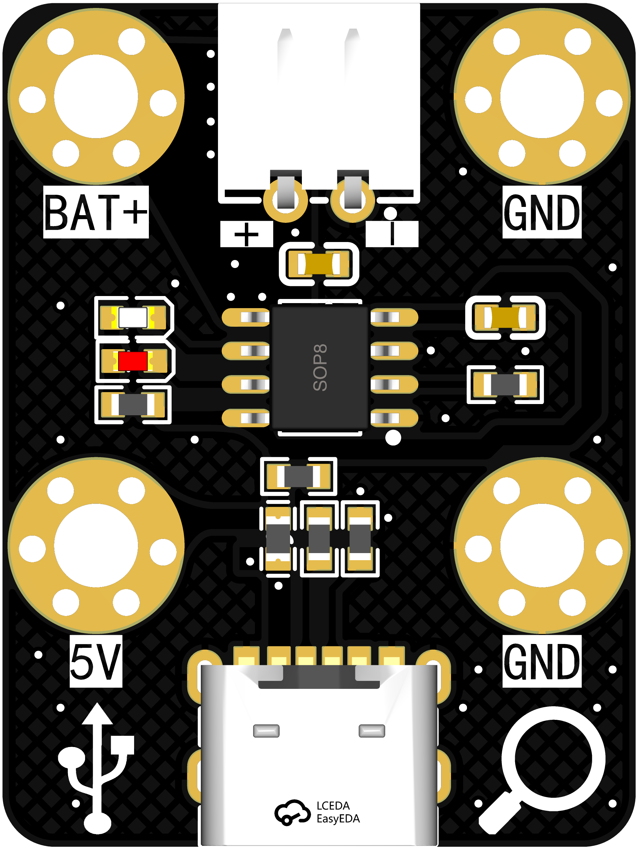
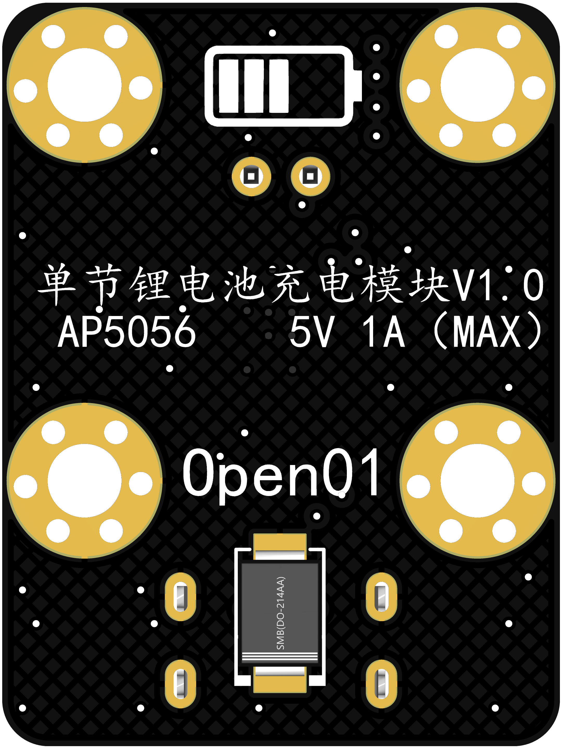
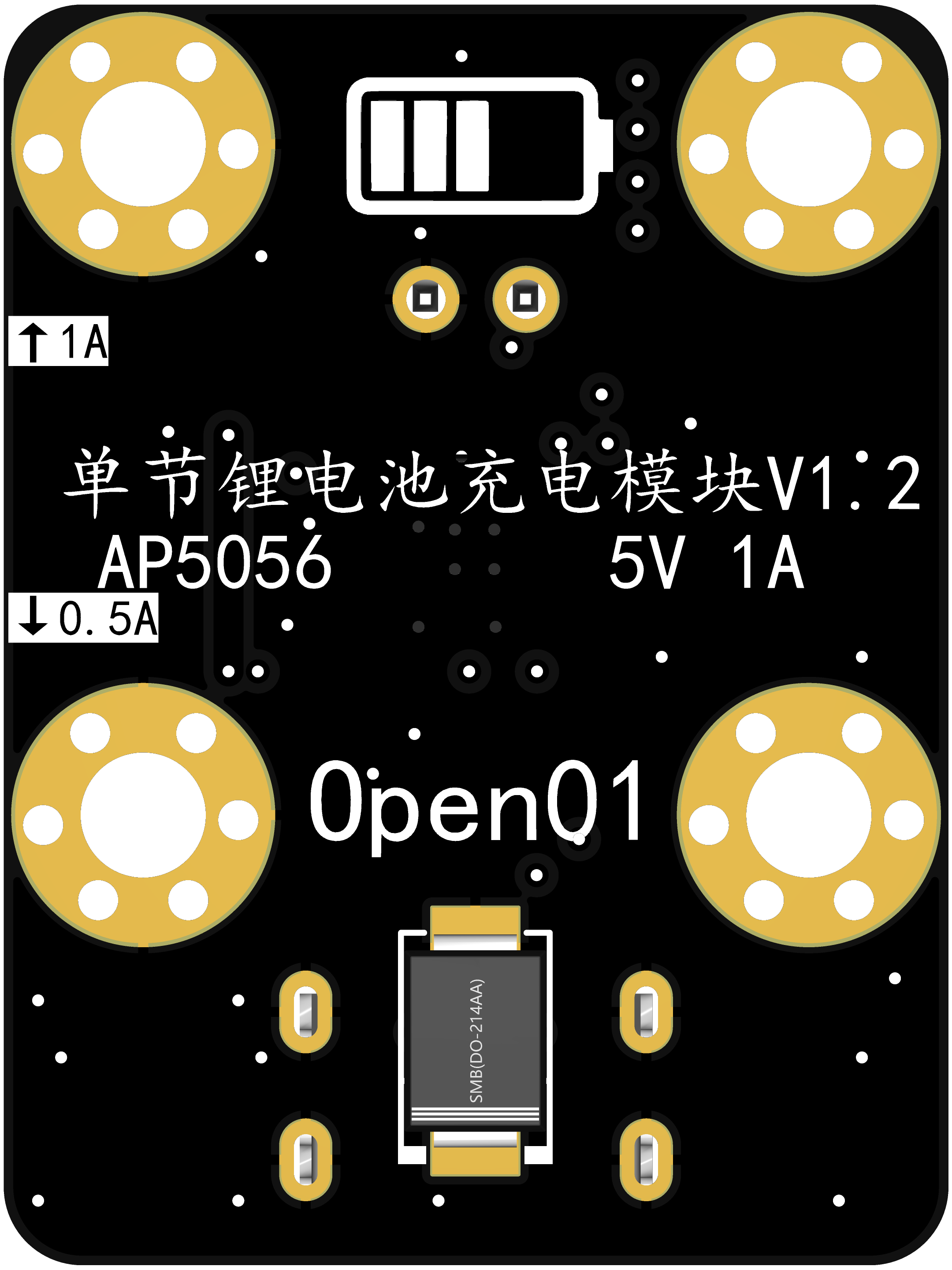
 , reflecting a cost-saving and efficiency-enhancing approach. This chip is compatible with the TP4056. U1 is a resettable fuse with a rated current of 1A, a trip current of 2A, and a maximum voltage of 6V. Both diagrams show the charging current control. The first diagram is for version V1.1, where current control is achieved through jumper pins. The second diagram is for version V1.2, where current control is achieved through a single DIP switch.
 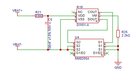 uses the common DW01 and 8205 chips for charge and discharge protection. The schematic is copied; I will study it further later and refine this part.
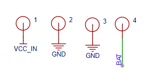
 The four screw holes, besides their mounting function, can also be used as power input and output, essentially providing an additional interface for charging to adapt to different scenarios.
All reference designs on this site are sourced from major semiconductor manufacturers or collected online for learning and research. The copyright belongs to the semiconductor manufacturer or the original author. If you believe that the reference design of this site infringes upon your relevant rights and interests, please send us a rights notice. As a neutral platform service provider, we will take measures to delete the relevant content in accordance with relevant laws after receiving the relevant notice from the rights holder. Please send relevant notifications to email: bbs_service@eeworld.com.cn.
It is your responsibility to test the circuit yourself and determine its suitability for you. EEWorld will not be liable for direct, indirect, special, incidental, consequential or punitive damages arising from any cause or anything connected to any reference design used.
Supported by EEWorld Datasheet
EEWorld
subscription
account

EEWorld
service
account

Automotive
development
community

Robot
development
community

About Us Customer Service Contact Information Datasheet Sitemap LatestNews


Room 1530, 15th Floor, Building B,
No.18 Zhongguancun Street,
Haidian District,
Beijing, Postal Code: 100190
China
Telephone: 008610 8235 0740
 京公网安备 11010802033920号

 CBP1255-56G


