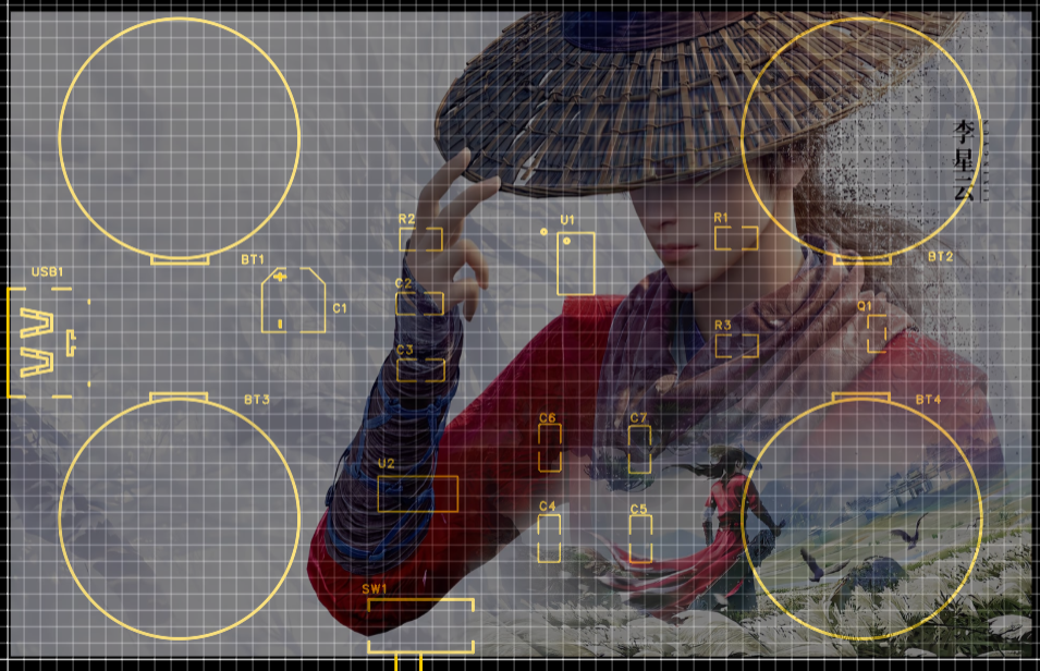
 2. First version of TP4056: Referencing the typical circuit provided in the chip datasheet and the circuit design in https://blog.csdn.net/eletronicfish/article/details/131671126 (thanks to the author for the open source)
  3. Second version of CR2032: A total of 4 cells were used, with two cells connected in series and two connected in parallel
 7. Manual Power Supply Selection: A mechanical selection mechanism was used
  8. Automatic Power Supply Selection: The circuit design in https://blog.csdn.net/eletronicfish/article/details/131671126 was referenced
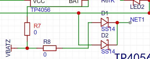

 A picture of Zhang Tian Anxing and Happy New Year was added to the bottom layer (~~to pass censorship~~)
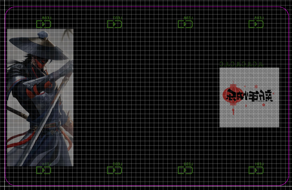
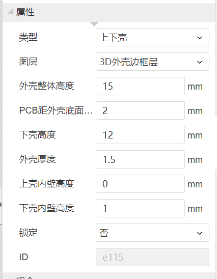 (depending on the situation)
  To allow light to pass through the bottom, cut grooves at the bottom
 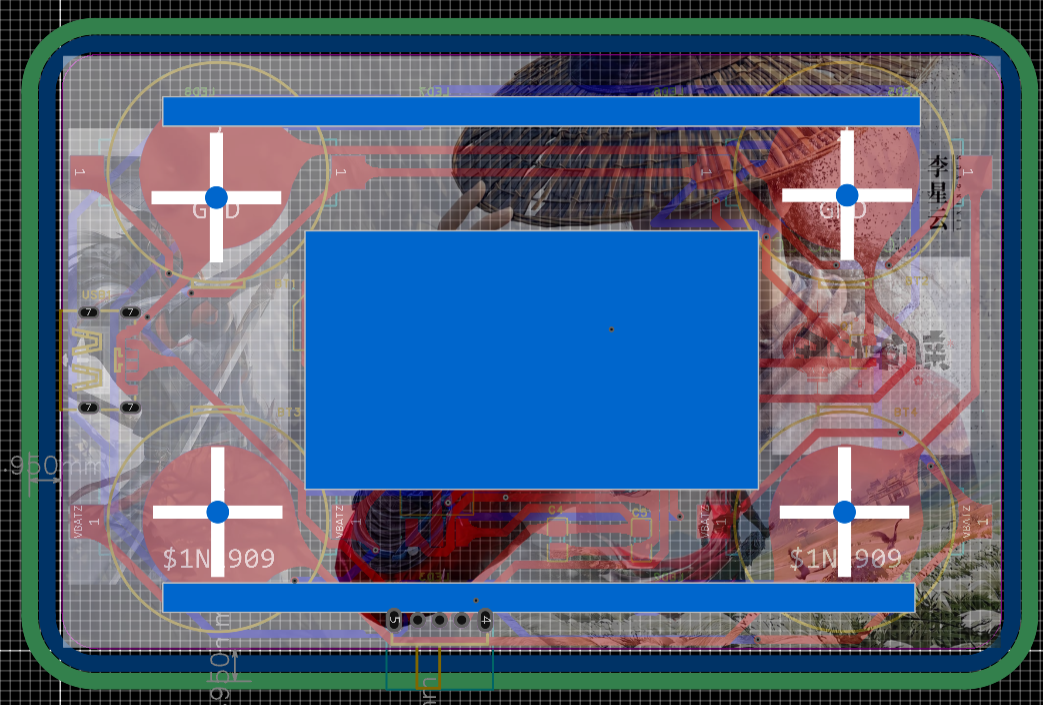 To fix the PCB, add screw posts The shell is done (dog head)

All reference designs on this site are sourced from major semiconductor manufacturers or collected online for learning and research. The copyright belongs to the semiconductor manufacturer or the original author. If you believe that the reference design of this site infringes upon your relevant rights and interests, please send us a rights notice. As a neutral platform service provider, we will take measures to delete the relevant content in accordance with relevant laws after receiving the relevant notice from the rights holder. Please send relevant notifications to email: bbs_service@eeworld.com.cn.
It is your responsibility to test the circuit yourself and determine its suitability for you. EEWorld will not be liable for direct, indirect, special, incidental, consequential or punitive damages arising from any cause or anything connected to any reference design used.
Supported by EEWorld Datasheet
EEWorld
subscription
account

EEWorld
service
account

Automotive
development
community

Robot
development
community

About Us Customer Service Contact Information Datasheet Sitemap LatestNews


Room 1530, 15th Floor, Building B,
No.18 Zhongguancun Street,
Haidian District,
Beijing, Postal Code: 100190
China
Telephone: 008610 8235 0740
 京公网安备 11010802033920号

 LHG35162


