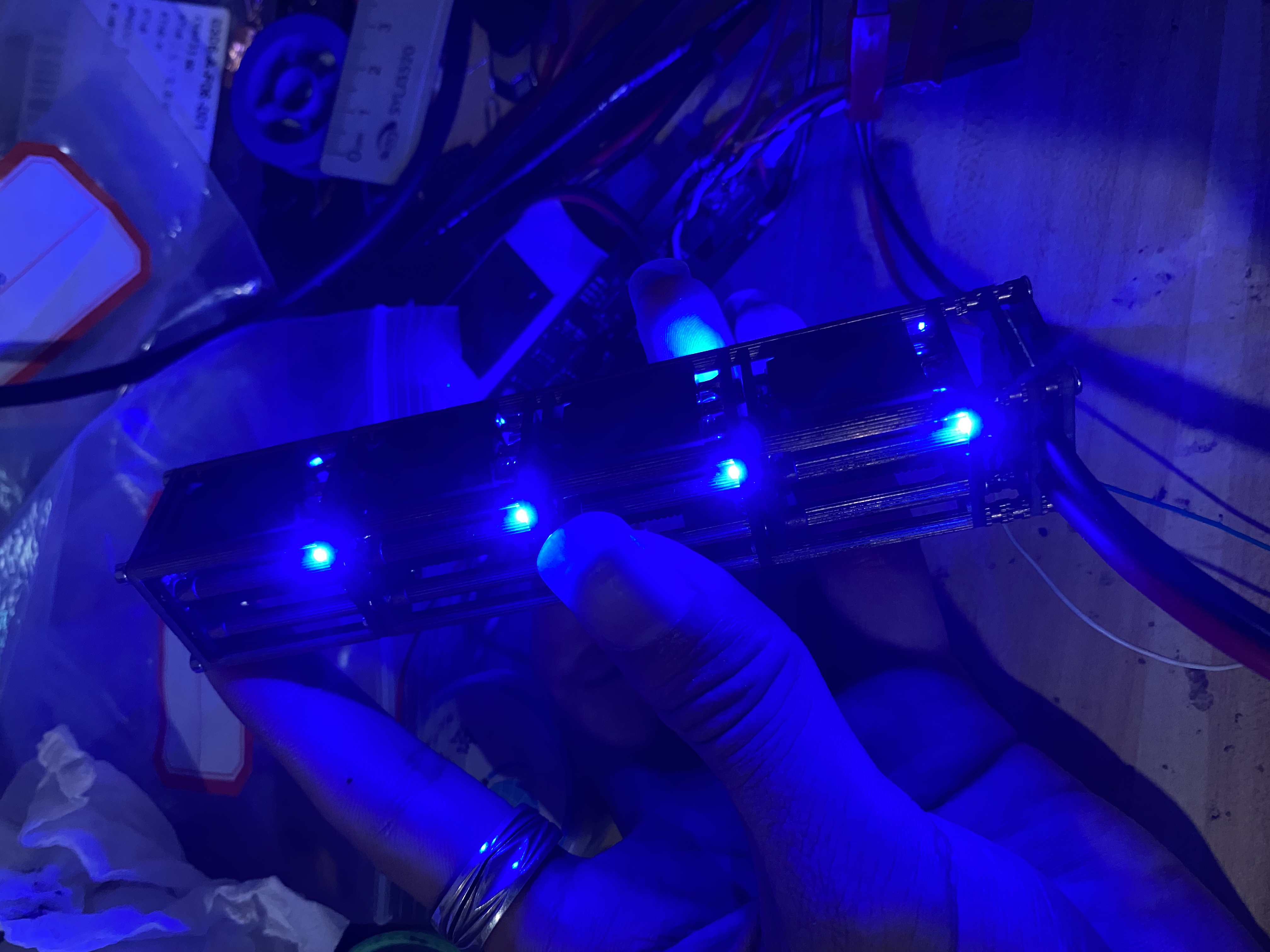
1. Battery charging and discharging management;
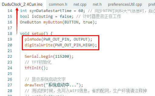
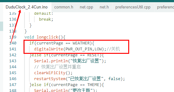
2. Power-on/off circuit. The following software modifications were made: 1. After the program runs, Q3 is turned on to supply power to the subsequent circuits. 2. A power-off function was added. Software notes: 1. Due to insufficient study of the source code, pin conflicts occurred. The original code used GPIO12 as a network indicator light; here, GPIO12 is used to output a high level to turn on Q3. Therefore, the statements operating on GPIO12 in the source code need to be commented out or deleted. Alternatively, you can use another pin as "PWR_OUT". After commenting it out, the function operating on D4 in net.cpp will compile with an error; commenting it out will resolve the issue. 2. At the beginning of program execution, PWR_OUT is controlled to output a high level. 3. A power-on function was added to the button event handling. When the interface is in the "clock interface", pressing and holding the button for 3 seconds will turn off the device.
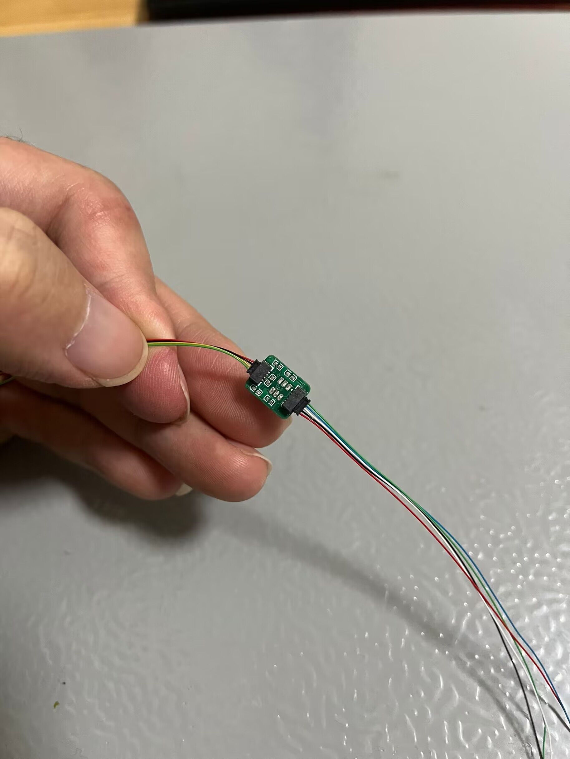
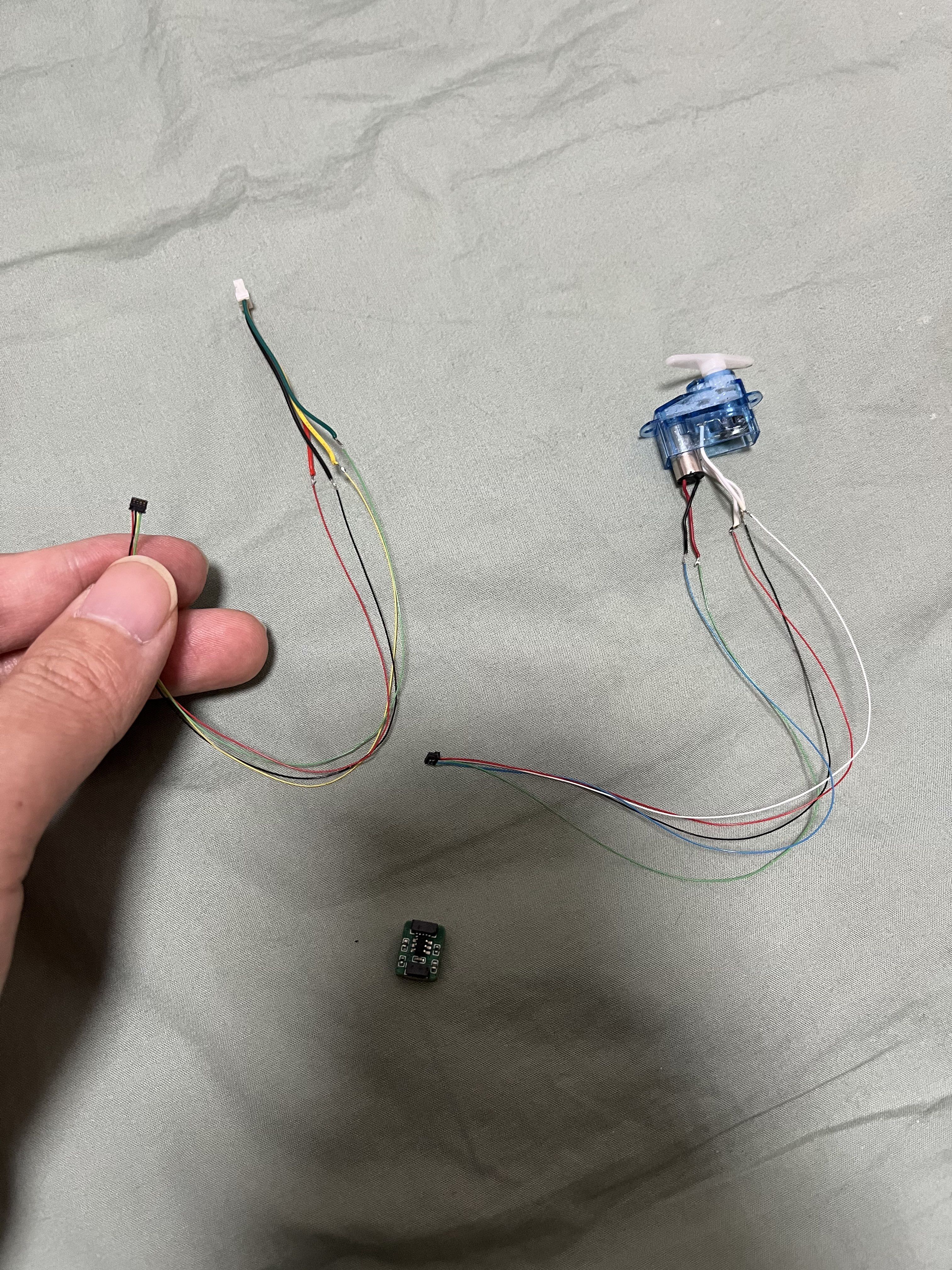
Based on the servo motor driver PCB board of the open-source project Electronbot by Zhihui Jun, since the original version and various modified versions still use wire bonding, which is inconvenient for programming and replacement, I made a slight modification to facilitate subsequent programming and disposal. It has been verified to be usable.
This description
is based on the servo drive PCB board of the open-source project Electronbot by Zhihui Jun. The wiring on both sides has been modified to use 4-pin and 5-pin connectors. Testing has shown it works correctly. This eliminates the need for soldering wires, making programming, assembly, and disposal easier. It has been verified as feasible. Compared to the original PCB, it is more compact during assembly, with better internal space for wire management, making assembly simpler and more convenient. Several other boards will be updated later to further simplify assembly.
Since the original and various modified versions still use soldering, programming and replacement are extremely inconvenient. Therefore, this modification facilitates subsequent programming and disposal. It has been verified as usable and is shared to help others build their own boards. A ready-made Gerb file is also uploaded as an attachment.
Special
thanks to: Lvyin (绿荫)
. This solution is based on Lvyin's modified suggestions and the final board verification.
Here is his Bilibili channel; you can follow him: Lvyin Aguang.
I also recommend his host computer software: ElectronBot.DotNet. (The latest version also supports Hanwen e-ink screen expansion modules!) Electronic Brain Store address:
Welcome to join the group for discussion: 147597938.
Also, I'd like to thank the following projects for giving me my own electronic robot (in no particular order):
Xiaoka Voice Version, Xiaopeng Study Version, Little Mage Improved Version
(Also, please follow my Bilibili collection!) ๑乛◡乛๑
Electronic Series Nanny Tutorial:
I've collected several videos sharing my experiences and pitfalls, which should solve most problems during the production process. Parts
List:
In addition to the original parts, you need to purchase the following two types of connector
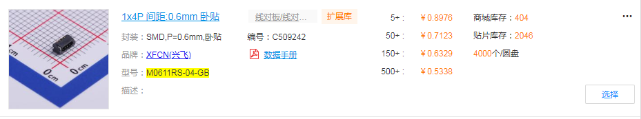
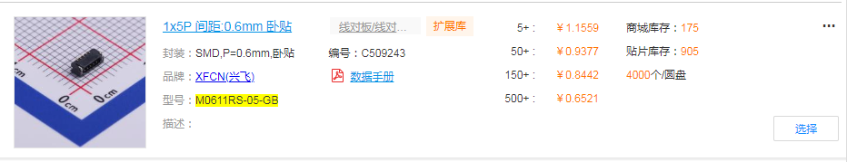
cables. Don't forget to buy
the spacing:
Pin count:
Single/Double
0.6mm
1*4,
Double
0.6mm
1*5. Here's a bare P-
type dual-ended
board
: (Forgive me for being a newbie; the board uses a pseudo-four-layer design). Welcome to continue optimizing and sharing!

This is the modified outline (mainly the wiring scheme at both ends).
I really revised it several times just for these two small terminals (^▽^).

This is a suggested placement scheme after the modification.
Looking at the comments on several related posts on Bilibili and forums, many people get stuck on the assembly.
The wiring at both ends of the modified board is more elegant and saves more space.

I suggest using heat-shrink
tubing although it's longer, the thin wires take up almost no space and won't increase the assembly difficulty

. This is the final result after discussion and practice:
finally achieving "modularization"!

1.mp4
2.mp4
Gerber_Modified ElectroBot_ServoDrive_PCB_2024-01-11.zip
PDF_【Open Source Modified Version】ElectronBot_ServoDrive.zip
Altium_【Open Source Modified Version】ElectronBot_ServoDrive.zip
PADS_【Open Source Modified Version】ElectronBot_ServoDrive.zip
BOM_【Open Source Modified Version】ElectronBot_ServoDrive.xlsx
96427
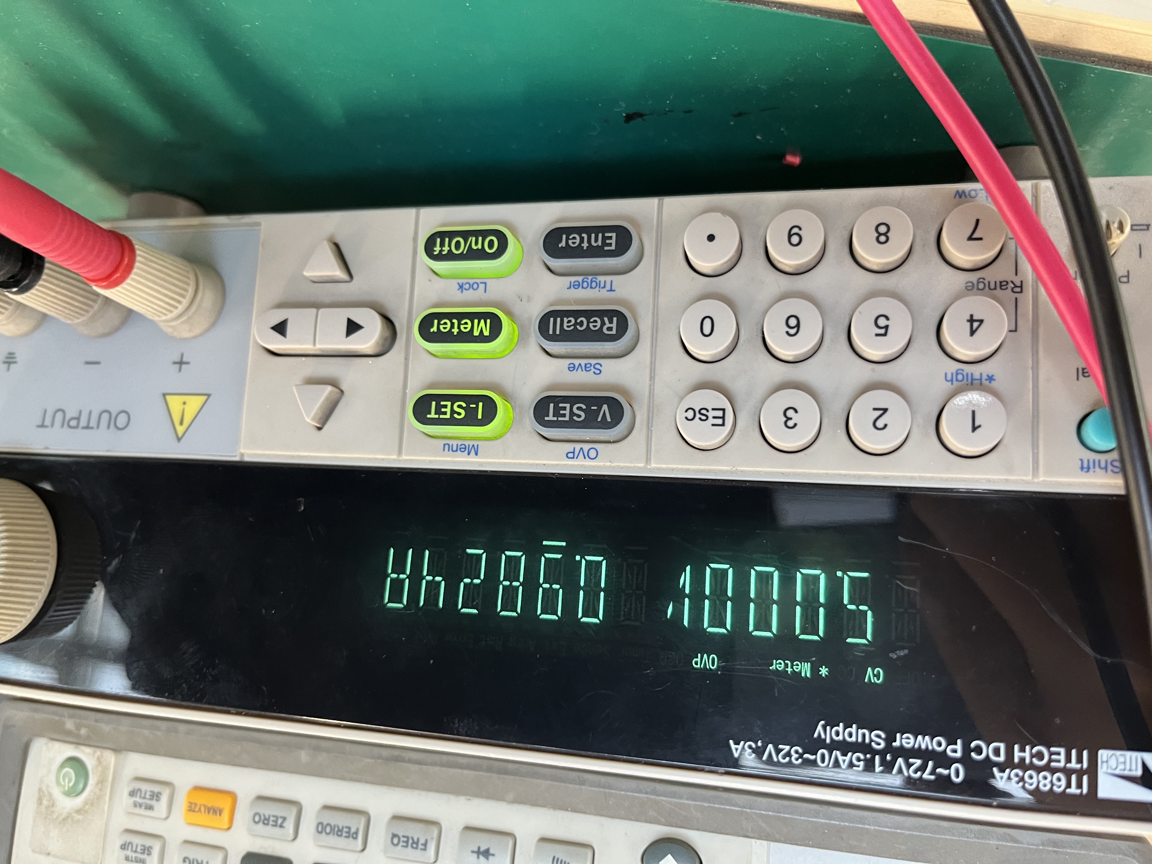
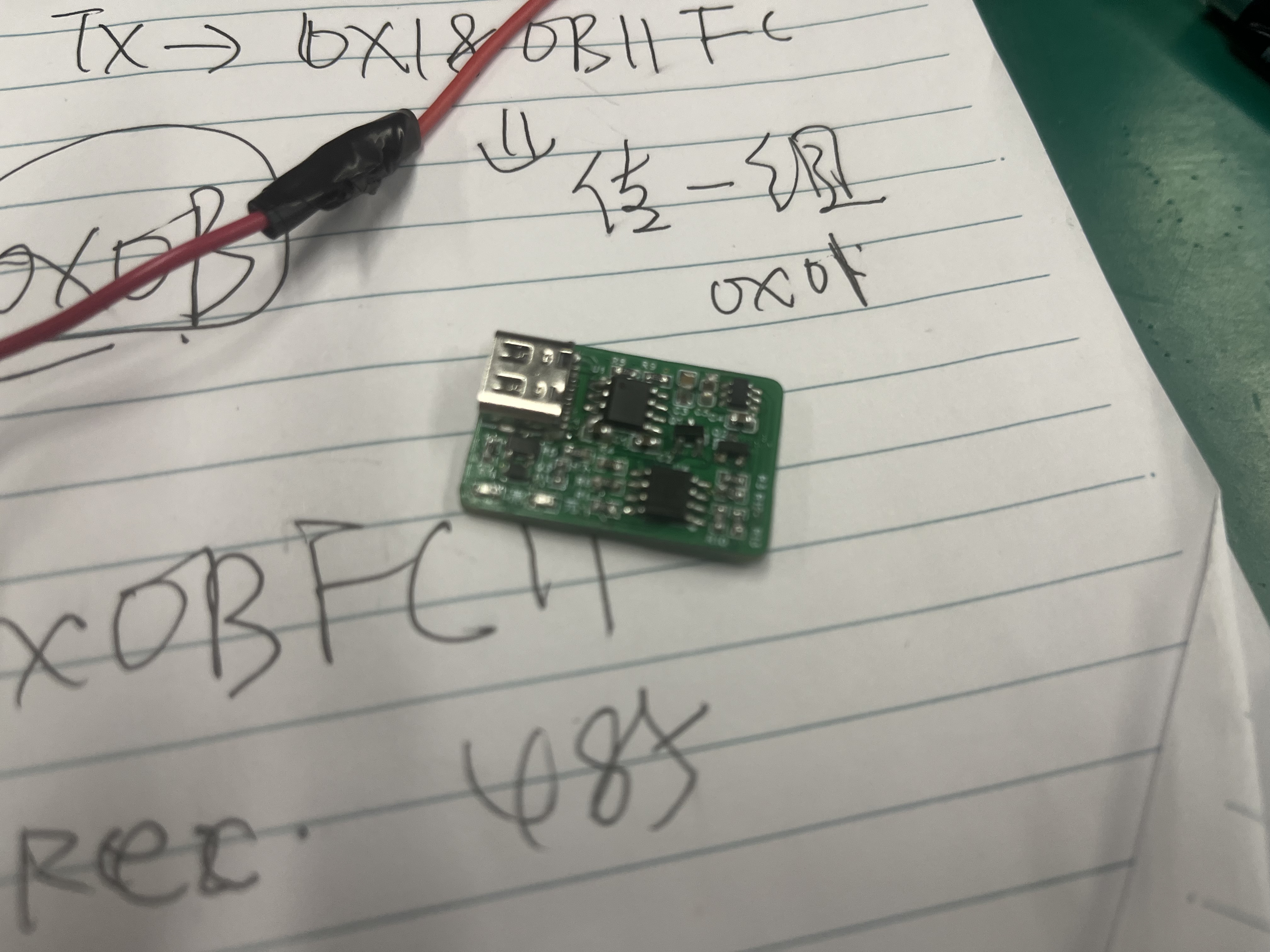
A 3.0 hub based on VL813, USB 1 to 4 adapter (certified and tested).
It uses the VL813 chip, which can replace the VL812 chip. Testing passed; both can transfer data. Test images have been uploaded; a SanDisk 32GB flash drive was used.
This project references: https://oshwhub.com/course-examples/usb-mo-kuai-3-0-ji-xian-qi. Thanks to JLCPCB's Bilibili tutorial; you can follow the steps to design this circuit board using JLCPCB's video tutorials on Bilibili. Later DIY soldering will require a hot air gun and related tools.
The original project used Type-C, the Bilibili tutorial video used Type-B, and this project uses a USB male connector.
It can be used to create a USB expansion port.


484ae6640a725bcb0674395ef618616c.mp4
PDF_VL813-based 3.0 HUB, USB 1 to 4 converter (certified and tested).zip
Altium_VL813-based 3.0 HUB, USB 1 to 4 converter (certified and tested).zip
PADS_VL813-based 3.0 HUB, USB 1 to 4 converter (certified and tested).zip
BOM_VL813-based 3.0 expansion dock HUB 1 to 4.xlsx
96428
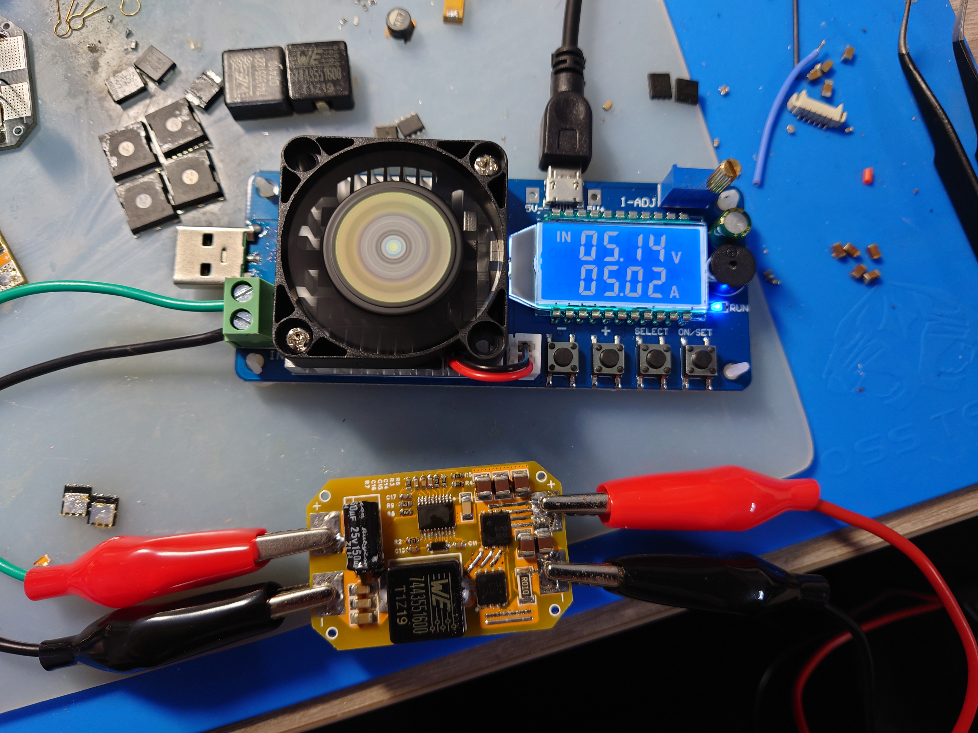
LM5116 step-down module verification board
A 5V 7A step-down module based on the LM5116 synchronous step-down controller, with a voltage input range of 9-60V.
LM5116 Features:
Peak current simulation mode;
Input voltage range up to 100 V;
Low shutdown current (
can drive standard or logic-level MOSFETs)
; Gate drive current up to 3.5 A;
Free-running or synchronous operation up to 1 MHz;
Selectable diode simulation mode;
Output voltage range 1.215 V to 80 V;
Voltage reference accuracy 1.5% ;
Programmable current limit
; Programmable soft start;
Programmable line undervoltage lockout;
Automatic switching to external bias power supply;
Thermal shutdown
; Input 24V, tested with a 5V/5A load; Enhanced heat dissipation required for long-term operation.
lm5116.pdf
PDF_LM5116 step-down module verification board.zip
Altium_LM5116 step-down module verification board.zip
PADS_LM5116 step-down module verification board.zip
BOM_LM5116 Step-Down Module Verification Board.xlsx
96429
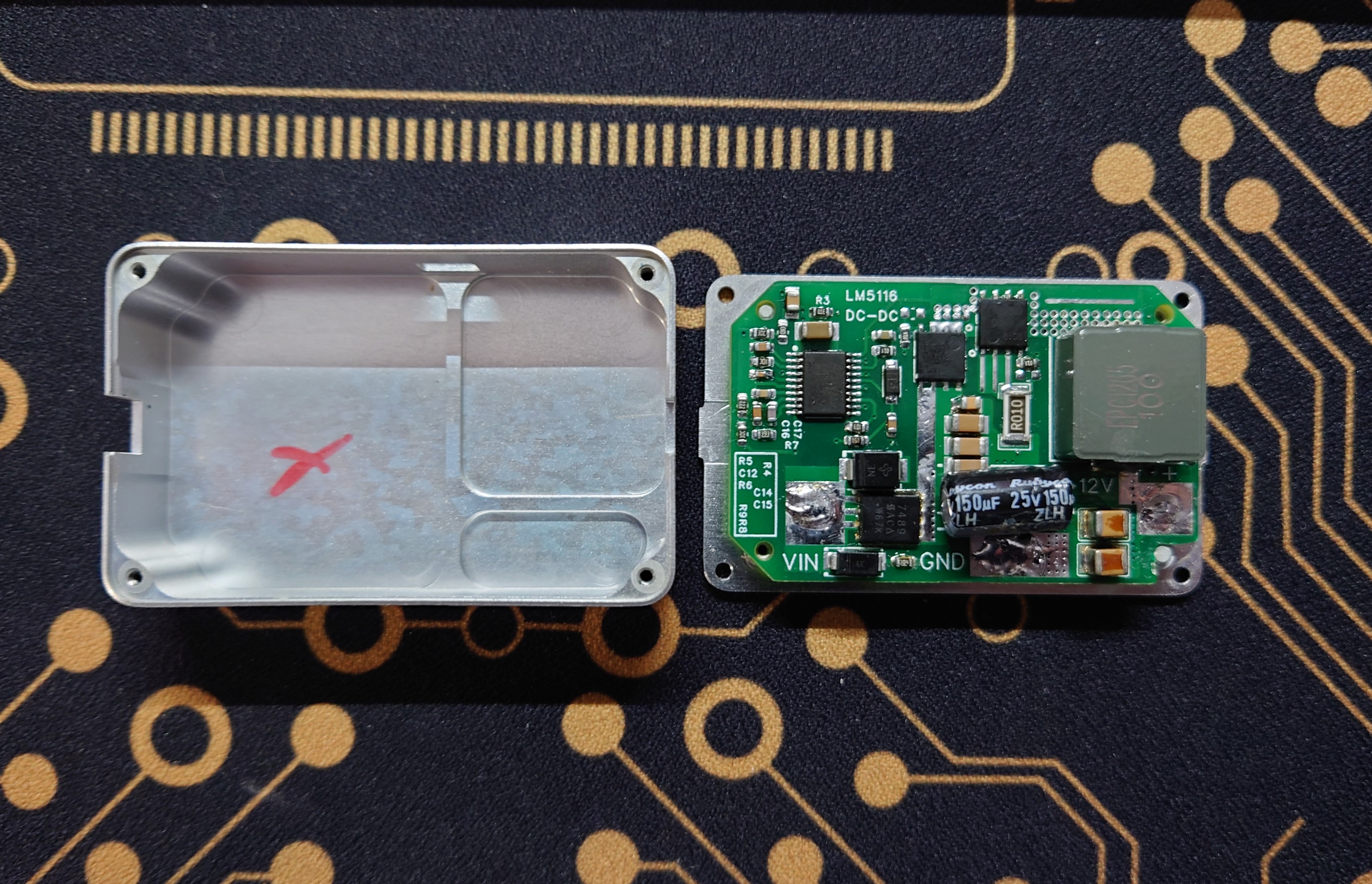
LM5116 step-down module 12V 5A verification board
A 12V 5A step-down module based on the LM5116 synchronous step-down controller, with a voltage input range of 15-60V.
LM5116 Features:
Peak current simulation mode;
Input voltage range up to 100 V;
Low shutdown current (
can drive standard or logic-level MOSFETs)
; Gate drive current up to 3.5 A;
Free-running or synchronous operation up to 1 MHz;
Selectable diode simulation mode;
Output voltage range 1.215 V to 80 V;
Voltage reference accuracy 1.5% ;
Programmable current limit
; Programmable soft start;
Programmable line undervoltage lockout;
Automatic switch to external bias power
supply; Thermal shutdown.
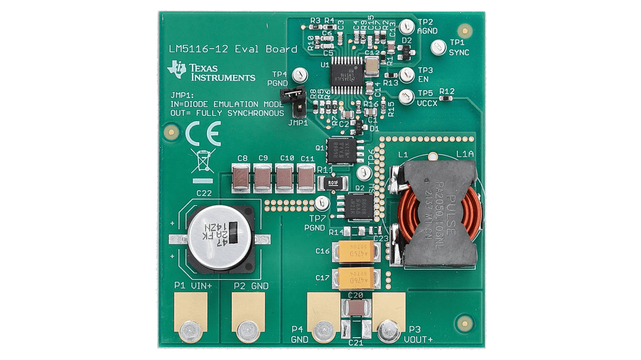
Schematic copied from TI official 12V board.
Input 24V, tested with 12V 2.8A load (maximum load 35W), can operate stably for a long time.
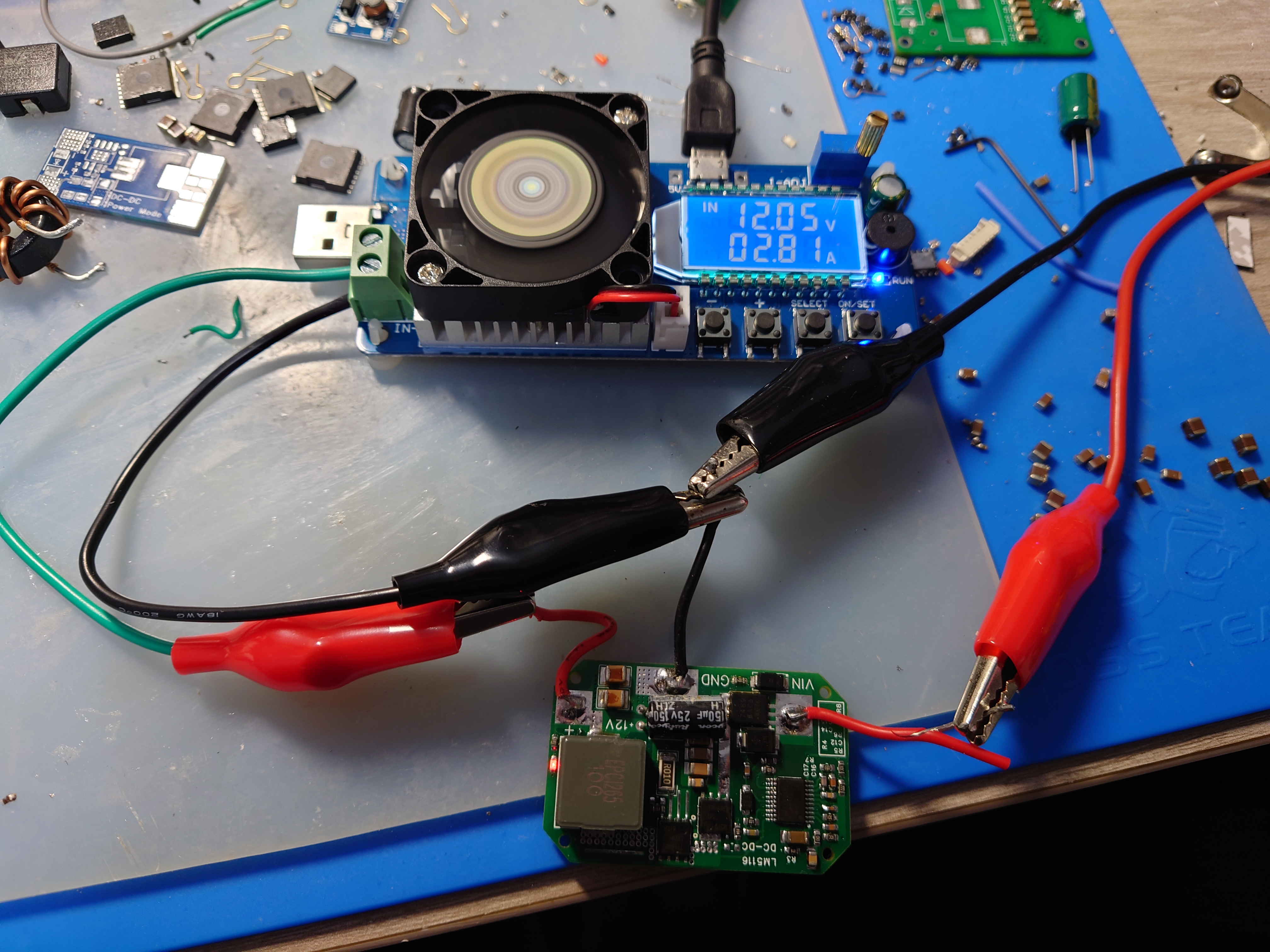
Size adapted to A3 flight controller PMU box, enhancing heat dissipation.
lm5116.pdf
LM5116_12V.pdf
PDF_LM5116 step-down module 12V 5A verification board.zip
Altium_LM5116 step-down module 12V 5A verification board.zip
PADS_LM5116 step-down module 12V 5A verification board.zip
BOM_LM5116 step-down module 12V 5A verification board.xlsx
96430
electronic
 The overvoltage and undervoltage protection range can be selected by adjusting the resistance values of R1, R6, and R7.


 京公网安备 11010802033920号

 MA1N6269TR


