This project references: https://oshwhub.com/course-examples/usb-mo-kuai-3-0-ji-xian-qi. Thanks to JLCPCB's Bilibili tutorial; you can follow the steps to design this circuit board using JLCPCB's video tutorials on Bilibili. Later DIY soldering will require a hot air gun and related tools.
The original project used Type-C, the Bilibili tutorial video used Type-B, and this project uses a USB male connector.
It can be used to create a USB expansion port.


484ae6640a725bcb0674395ef618616c.mp4
PDF_VL813-based 3.0 HUB, USB 1 to 4 converter (certified and tested).zip
Altium_VL813-based 3.0 HUB, USB 1 to 4 converter (certified and tested).zip
PADS_VL813-based 3.0 HUB, USB 1 to 4 converter (certified and tested).zip
BOM_VL813-based 3.0 expansion dock HUB 1 to 4.xlsx
96428
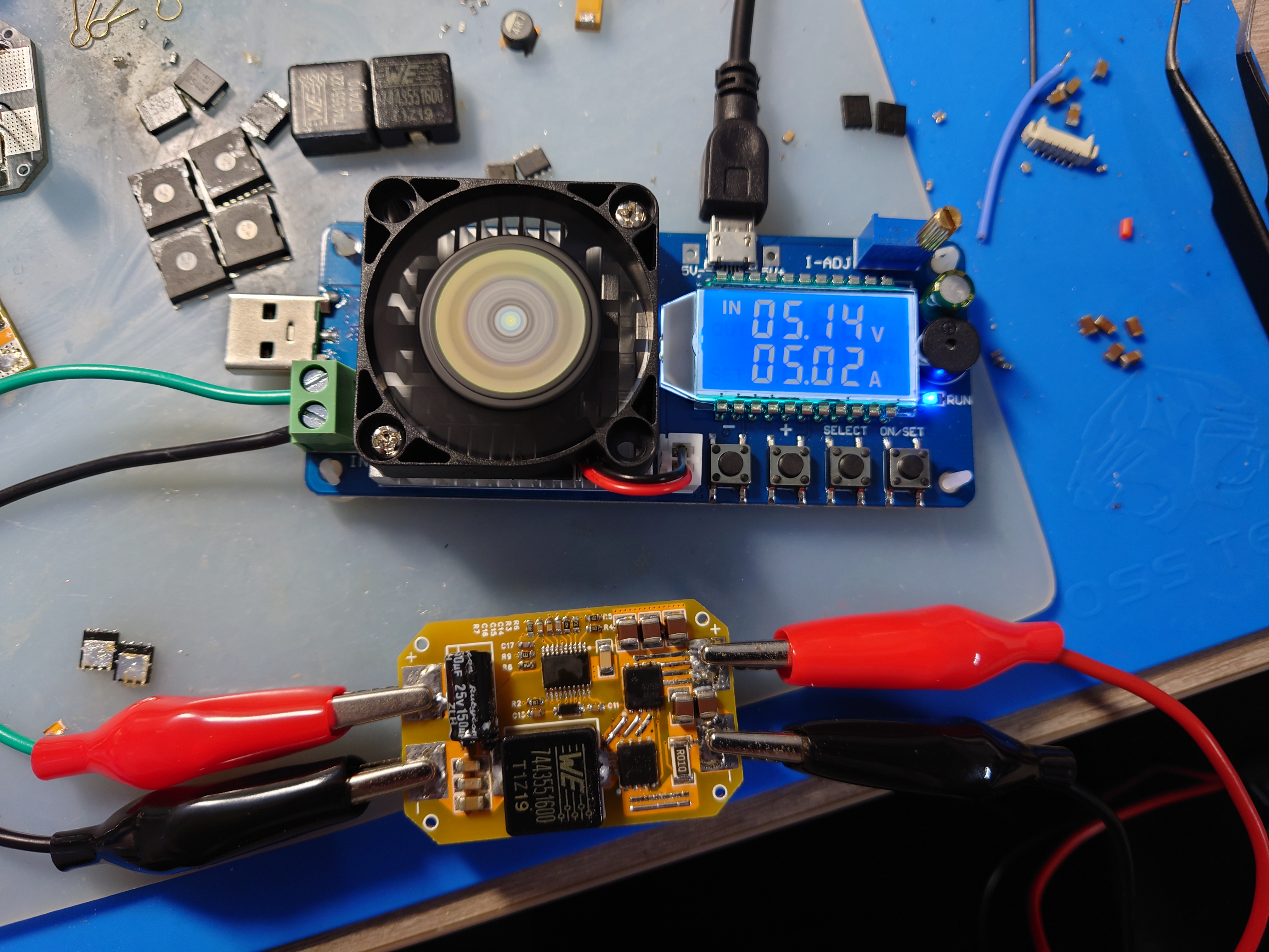
LM5116 step-down module verification board
A 5V 7A step-down module based on the LM5116 synchronous step-down controller, with a voltage input range of 9-60V.
LM5116 Features:
Peak current simulation mode;
Input voltage range up to 100 V;
Low shutdown current (
can drive standard or logic-level MOSFETs)
; Gate drive current up to 3.5 A;
Free-running or synchronous operation up to 1 MHz;
Selectable diode simulation mode;
Output voltage range 1.215 V to 80 V;
Voltage reference accuracy 1.5% ;
Programmable current limit
; Programmable soft start;
Programmable line undervoltage lockout;
Automatic switching to external bias power supply;
Thermal shutdown
; Input 24V, tested with a 5V/5A load; Enhanced heat dissipation required for long-term operation.
lm5116.pdf
PDF_LM5116 step-down module verification board.zip
Altium_LM5116 step-down module verification board.zip
PADS_LM5116 step-down module verification board.zip
BOM_LM5116 Step-Down Module Verification Board.xlsx
96429
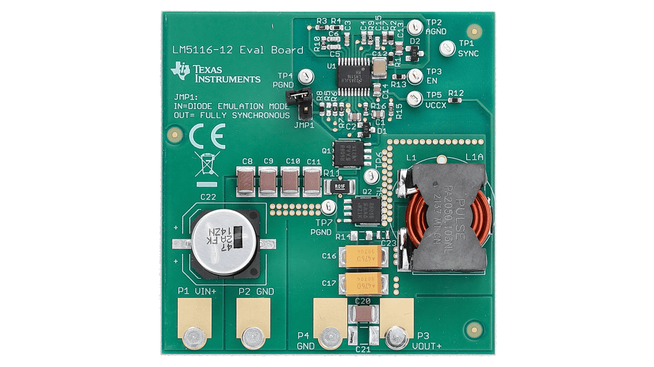
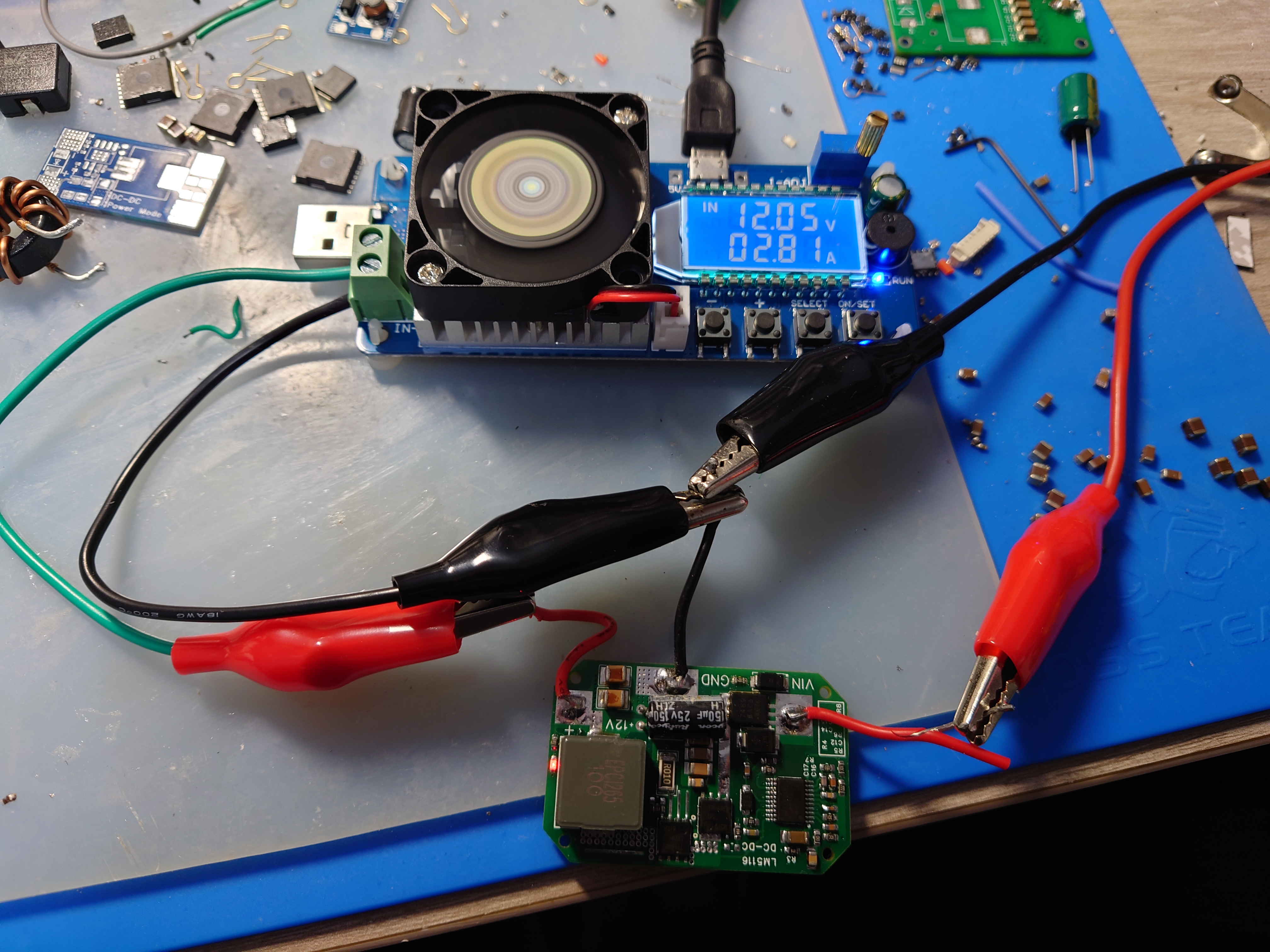
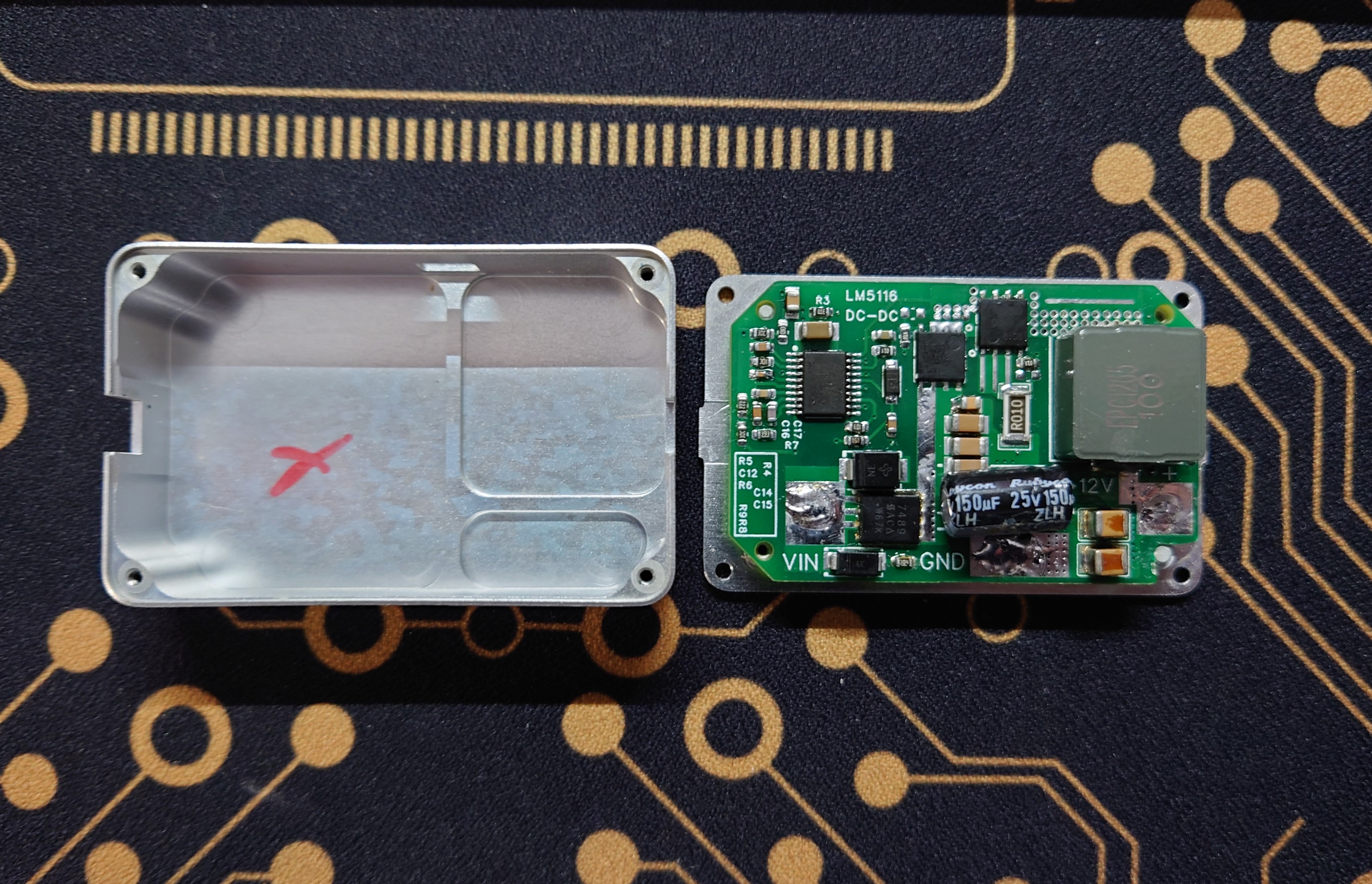
LM5116 step-down module 12V 5A verification board
A 12V 5A step-down module based on the LM5116 synchronous step-down controller, with a voltage input range of 15-60V.
LM5116 Features:
Peak current simulation mode;
Input voltage range up to 100 V;
Low shutdown current (
can drive standard or logic-level MOSFETs)
; Gate drive current up to 3.5 A;
Free-running or synchronous operation up to 1 MHz;
Selectable diode simulation mode;
Output voltage range 1.215 V to 80 V;
Voltage reference accuracy 1.5% ;
Programmable current limit
; Programmable soft start;
Programmable line undervoltage lockout;
Automatic switch to external bias power
supply; Thermal shutdown.
Schematic copied from TI official 12V board.
Input 24V, tested with 12V 2.8A load (maximum load 35W), can operate stably for a long time.
Size adapted to A3 flight controller PMU box, enhancing heat dissipation.
lm5116.pdf
LM5116_12V.pdf
PDF_LM5116 step-down module 12V 5A verification board.zip
Altium_LM5116 step-down module 12V 5A verification board.zip
PADS_LM5116 step-down module 12V 5A verification board.zip
BOM_LM5116 step-down module 12V 5A verification board.xlsx
96430
electronic


 京公网安备 11010802033920号

 2SK3715


