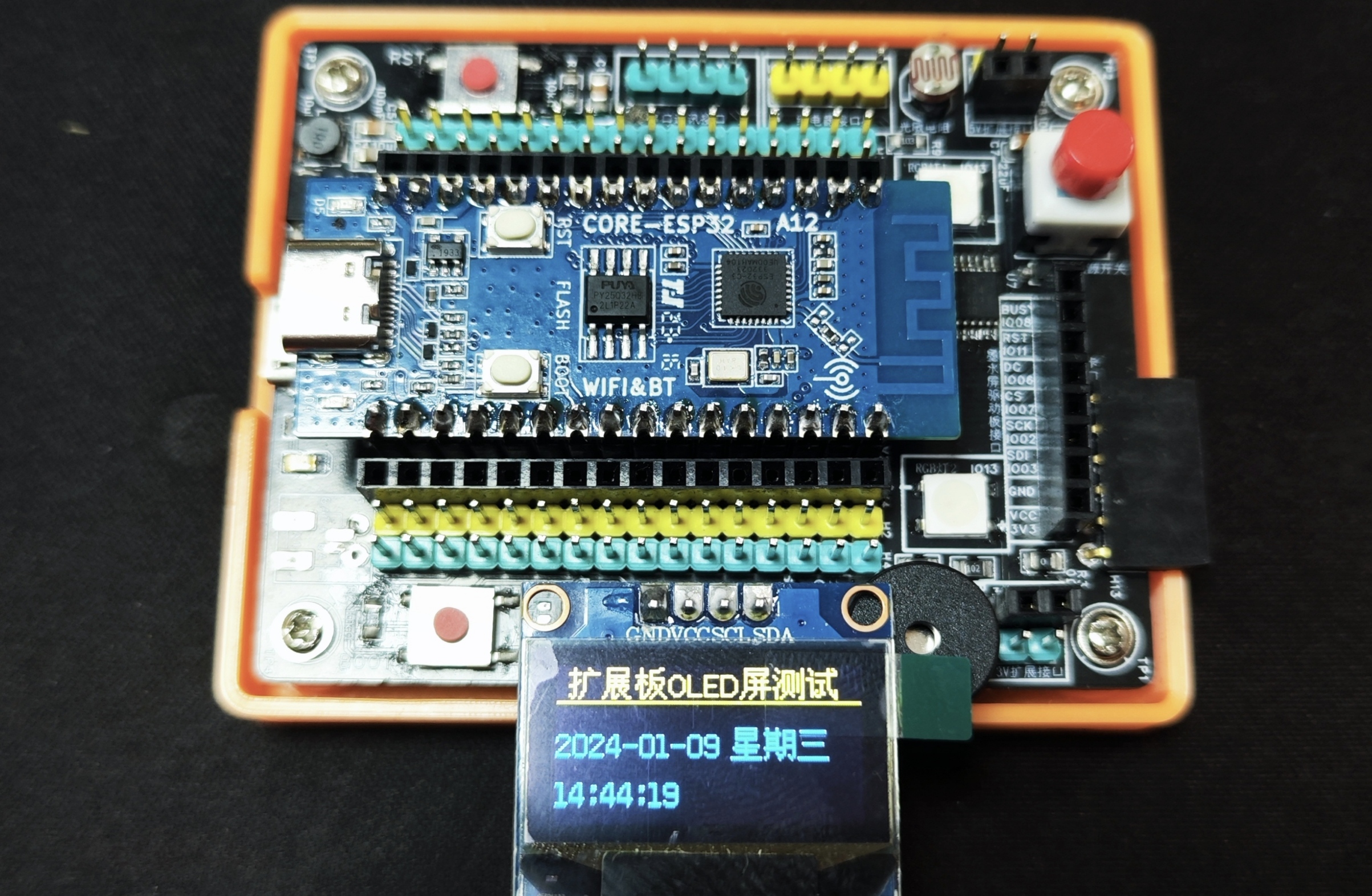
This expansion board is compatible with the Zephyrus ESP32C3 development board, bringing out all pins. It features
an onboard TP5400 chip, providing 3.7V lithium battery charging protection and a boost output to 5V. When the USB port is connected, it uses external power; when the external power is disconnected, it automatically
switches to lithium battery power. The expansion board has 1.0mm and 1.25mm battery terminal blocks on both sides, with independent battery switch control.
The board integrates a photoresistor, an AHT20 temperature and humidity sensor, an active buzzer, a 74HC595 chip controlling eight blue LEDs, and two WS2812 RGB LEDs. A DS1302 clock chip is located on the back.
It features I2C, relay, TF card, and SPI expansion interfaces, as well as TX/RX, 3.3V, and 5V interfaces.
The I2C and SPI expansion interfaces have been tested with OLED and e-ink screens respectively.
Due to space limitations, a 1220 battery holder is used for the DS1302 clock chip on the back.
Due to the limited number of interfaces on the ESP32C3 development board, some GPIO ports have been reused. Special attention should be paid to this when writing code.
All functions have been verified on the board.
1. The image shows the first version of the board; the AHT20 temperature and humidity sensor chip is not soldered.
2. The first version's RST button only resets the device. The second version has been modified by adding a selection circuit. During soldering, you can connect to GPIO21 for use as an input button. For resetting, you can use the development board's built-in reset button.
3. The DS1302 clock chip and 74HC595 chip reuse GPIO18 and GPIO19 pins (USB communication pins). If you use the simplified version of the HeZhou ESP32C3 for programming, the development board's USB automatic download function will be disabled; you will need to manually enter download mode. Using the standard version of the HeZhou ESP32C3 is unaffected.
4. This expansion board is designed for personal use; any errors are welcome for discussion.
A power-on card that enables remote management, not limited by a local area network. As long as there is internet access, you can easily remotely start your computer. More details will be provided in future updates.
This is a power-on card that enables remote management. It's not limited by a local area network; as long as there's internet access, you can easily remotely power on your computer. It also supports scheduled control and allows you to set conditions for control via your mobile phone.
PDF_ESP8266 computer boot card.zip
Altium_ESP8266 computer boot card.zip
PADS_ESP8266 computer boot card.zip
BOM_ESP8266 Computer Boot Card.xlsx
96470
LED_ESP01S_2023-10-06_20-50-47
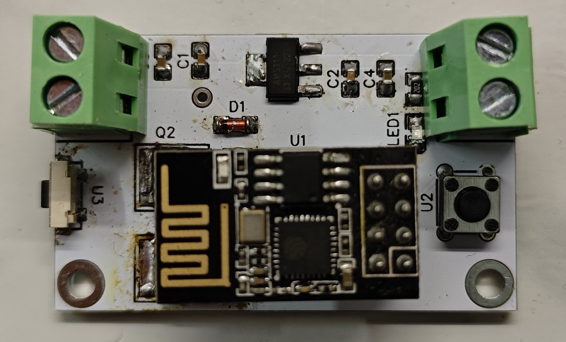
This is an LED light controller circuit based on the ESP01S, which is a hardware circuit for a smart light.
Connect
the VIN pin of this circuit to a +5V power supply, and connect the GND pin to the power ground. Connect the VOUT pin of the circuit to the positive terminal of the LED, and connect the GND pin to the negative
terminal of the LED.
This hardware uses an ESP01S
IO2 pin to connect to the button
IO0 pin, which in turn connects to dual NMOS transistors
. The LED can be turned on/off by programming the ESP01S. The brightness of the LED
can also be controlled via PWM. The IoT functionality of the ESP01S can also be used to implement this small LED. (
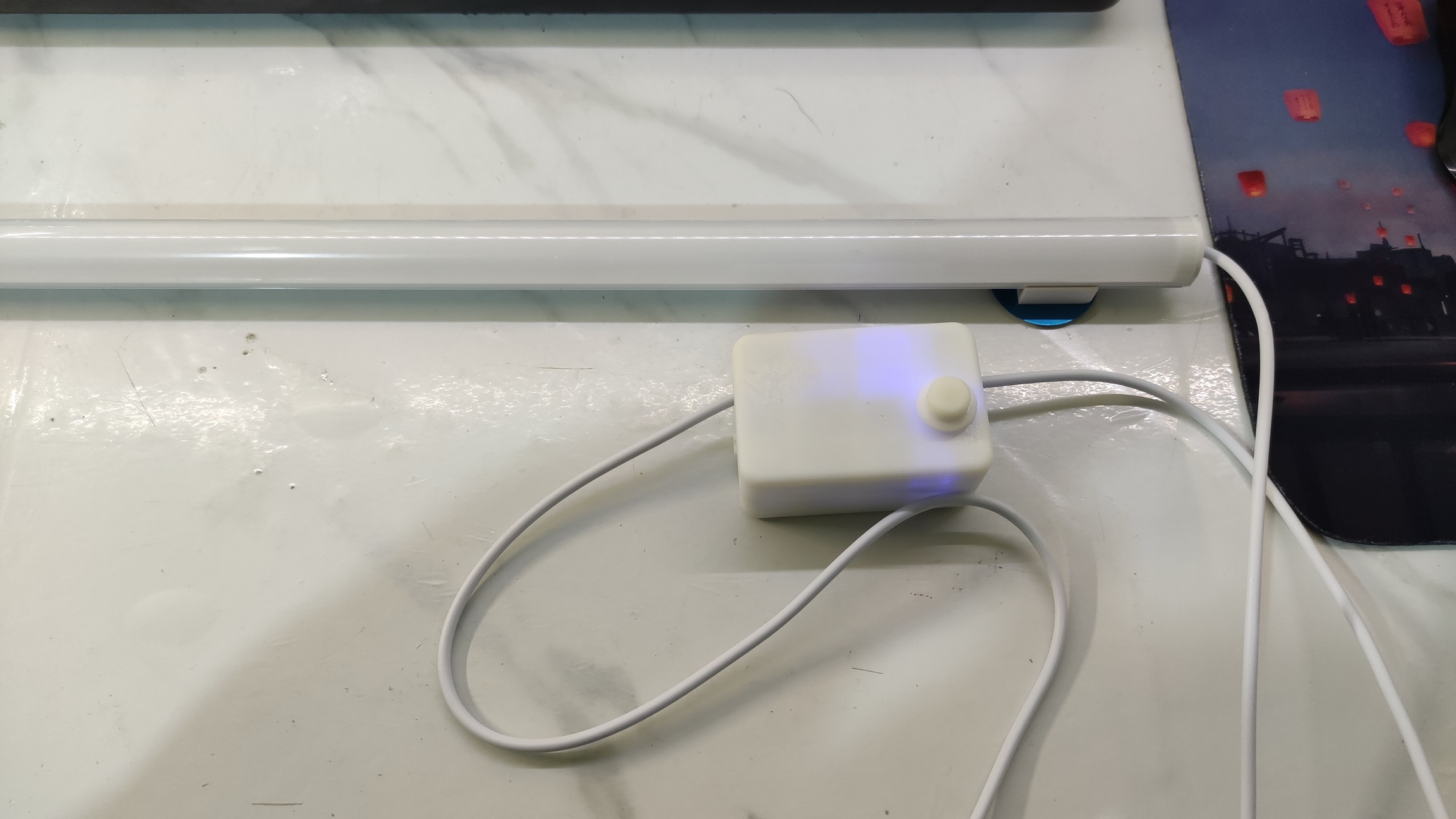
A physical demonstration of the small LED - verified.
The soldering technique is not very good, please bear with it.) The circuit has been verified and meets the requirements.


PDF_LED_ESP01S_20-50-47.zip
Altium_LED_ESP01S_20-50-47.zip
PADS_LED_ESP01S_20-50-47.zip
BOM_LED_ESP01S_2023-10-06_20-50-47.xlsx
96472
TRX001_120GHz (AD8231ZAPZ)
Radar ranging (dynamic)
This project aims to accurately measure dynamic objects (objects that reflect microwaves). With the support of algorithms, it can reach the micrometer level. A 120GHz radar chip is used. We hope everyone will actively participate in the discussion.
PDF_TRX001_120GHz(AD8231ZAPZ).zip
Altium_TRX001_120GHz (AD8231ZAPZ).zip
PADS_TRX001_120GHz (AD8231ZAPZ).zip
96473
ESP32-DevKitC Core Development Board
The ESP32-Devkitc core development board uses a Type-C interface, the CH340C supports automatic downloading, and features a 25.36mm pin header width.
This is an ESP32-Devkitc core development board using a Type-C interface. The CH340C supports automatic downloading, and the pin header width is 25.36mm.
Because this specification is hard to find online or is expensive, this project was created to make it easier for everyone to use this module.
To facilitate manual construction, components are placed on the top layer, and most surface-mount components are 0603 specification.
Finished product demonstration (verified).

There is a small issue here: RX and TX were reversed in the schematic design. The above diagram temporarily solves this with a jumper wire. The schematic has been updated. Please see the attached
verification video .
Serial port connection information retrieval.mov
PDF_ESP32-DevKitC Core Development Board.zip
Altium_ESP32-DevKitC Core Development Board.zip
PADS_ESP32-DevKitC Core Development Board.zip
BOM_ESP32-DevKitC Core Development Board.xlsx
96474
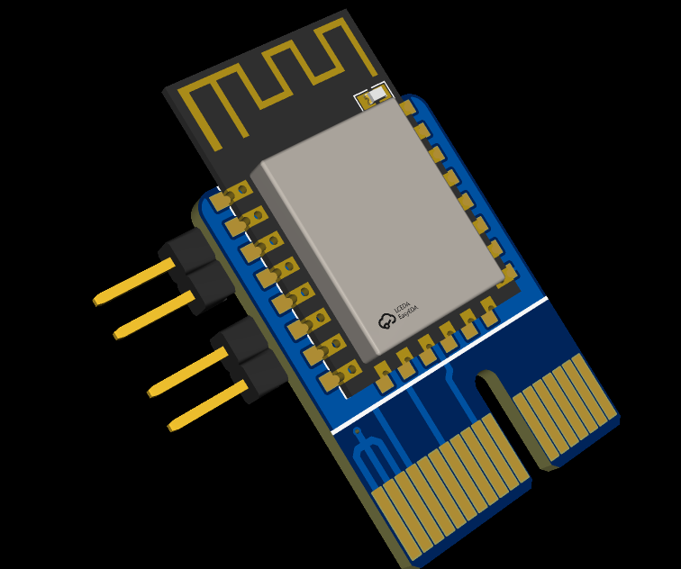
LicheePi Nano Docker Expansion Board
A simple expansion board designed for LicheePi Nano
This simple expansion board designed for LicheePi
brings out all I/O pins
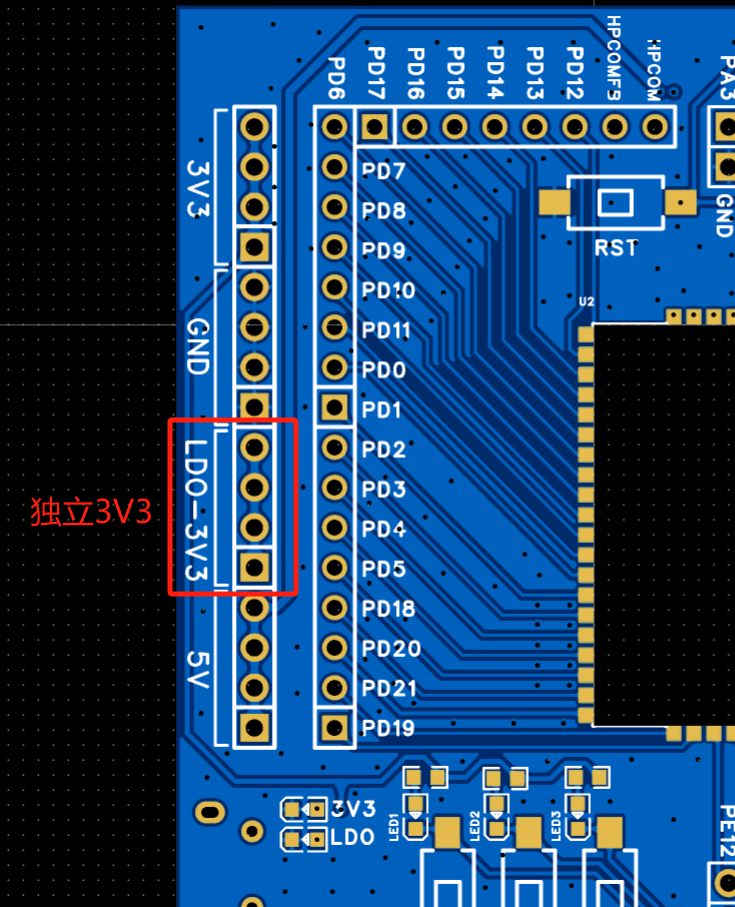
and adds an independent 3V3 power supply. It also provides multiple additional power pins: 5V, 3V3, and GND.
The independent 3V3 uses an LDO for power, the 5V is directly derived from the USB and shared with the LicheePi Nano, and the 3V3 is derived from the LicheePi Nano's built-in DC-DC converter, resulting in limited power supply capacity.
If peripherals have high power consumption, connect them to an LDO-3V3 or 5V for power.
A reset button is added to avoid the inconvenience of having to repeatedly power on and off to reset.
Three LEDs and three switches are provided, connected to PE4, PE5, and PE6, which can display voltage levels and act as inputs.
The board's width matches that of the core board, allowing it to be soldered regardless of whether the core board has already been soldered with headers.
The board also brings out the USB, with functionality essentially the same as the USB on the core board, except it lacks OTG (meaning no ID cable is connected). Programs can be burned via the expansion board's USB, reducing the use of ports on the core board and extending its lifespan.
Disp2.jpg
Disp1.jpg
Disp3.jpg
Demo.mp4
PDF_LicheePi Nano Docker LicheePi Nano Expansion Board.zip
Altium_LicheePi Nano Docker LicheePi Nano Expansion Board.zip
PADS_LicheePi Nano Docker LicheePi Nano Expansion Board.zip
BOM_LicheePi Nano Docker LicheePi Nano Expansion Board.xlsx
96475
dTOF_module
I designed a small module based on the ADS6102 single-point laser rangefinder from Adams.
Using I2C communication to read ranging data from a consumer-grade TOFI chip.
PDF_dTOF_module.zip
Altium_dTOF_module.zip
PADS_dTOF_module.zip
BOM_dTOF_module.xlsx
96477
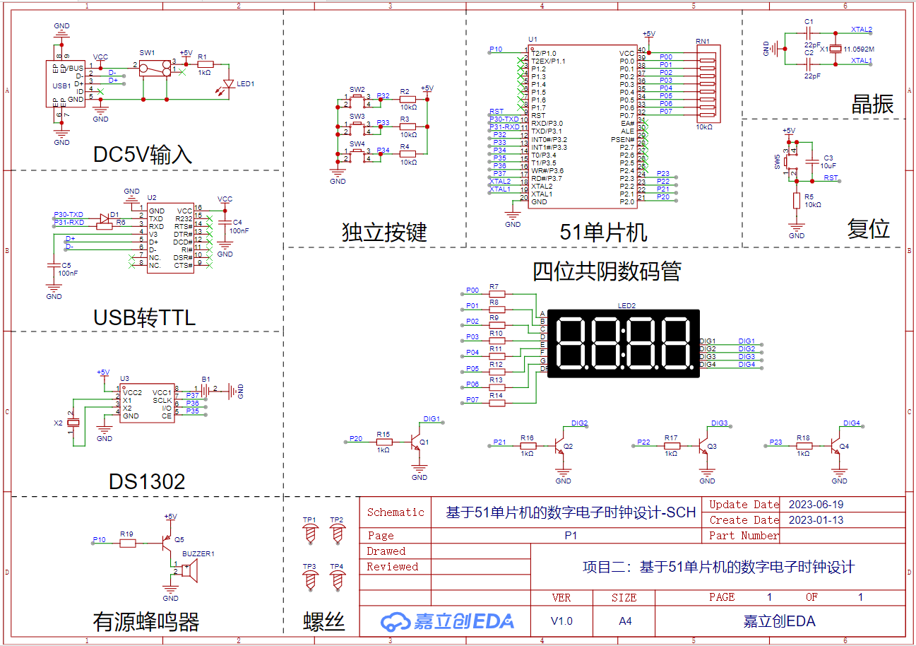
Project 2: Design of a Digital Electronic Clock Based on a 51 Microcontroller
This project is Project 2 of the textbook "Case Study Tutorial for Electronic Product Design (Micro-course Edition) - Based on JLCPCB EDA (Professional Edition)": Design of a digital electronic clock based on the 51 microcontroller.
I. Project Introduction
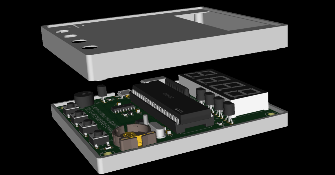
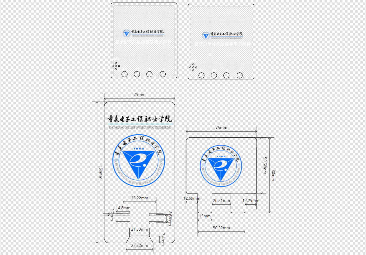
Through the learning and creation of the "Digital Electronic Clock Based on 51 Microcontroller" project case, participants will become familiar with the overall process of electronic product design and development, be able to quickly and efficiently use the JLCPCB EDA (Professional Edition) editor for schematic and PCB design, combine PCB and 3D structural design, become familiar with the basic concepts of casing design, complete simple electronic product casing designs, and master the process, design, and production of acrylic panels. II

. Overall Solution
The design is based on the STC89C52RC microcontroller. The power input uses a recessed Micro-B USB connector interface. An onboard CH340C clock is used for program downloading via the Micro-B interface. A DS1302 clock chip is used, and a button battery is used to save time data when power is off. Onboard system reset button and set/increase/decrease function buttons are included. An active buzzer is reserved, and a four-digit common cathode LED display shows the time. [Schematic, PCB , 3D casing, and
actual panel image are included.]


51_CLOCK_DEMO.zip
PDF_Project 2: Digital Electronic Clock Design Based on 51 Microcontroller.zip
Altium_Project 2: Digital Electronic Clock Design Based on 51 Microcontroller.zip
PADS_Project 2: Digital Electronic Clock Design Based on 51 Microcontroller.zip
96478
Project 1: Multivibrator
This project is Project 1 of the textbook "Case Study Tutorial for Electronic Product Design (Micro-course Edition) - Based on JLCPCB EDA (Professional Edition)": Multivibrator.
I. Project Introduction
Through the study and creation of the "Multivibrator" project case, participants will gain a preliminary understanding of the functions of JLCPCB EDA (Professional Edition) and be able to perform simple schematic and PCB design.
II. Overall Scheme
This oscillator uses resistor-capacitor coupling to alternately turn two transistors on and off, thereby generating a square wave output. After power-on, it automatically generates a rectangular clock without requiring an external pulse.
Schematic,
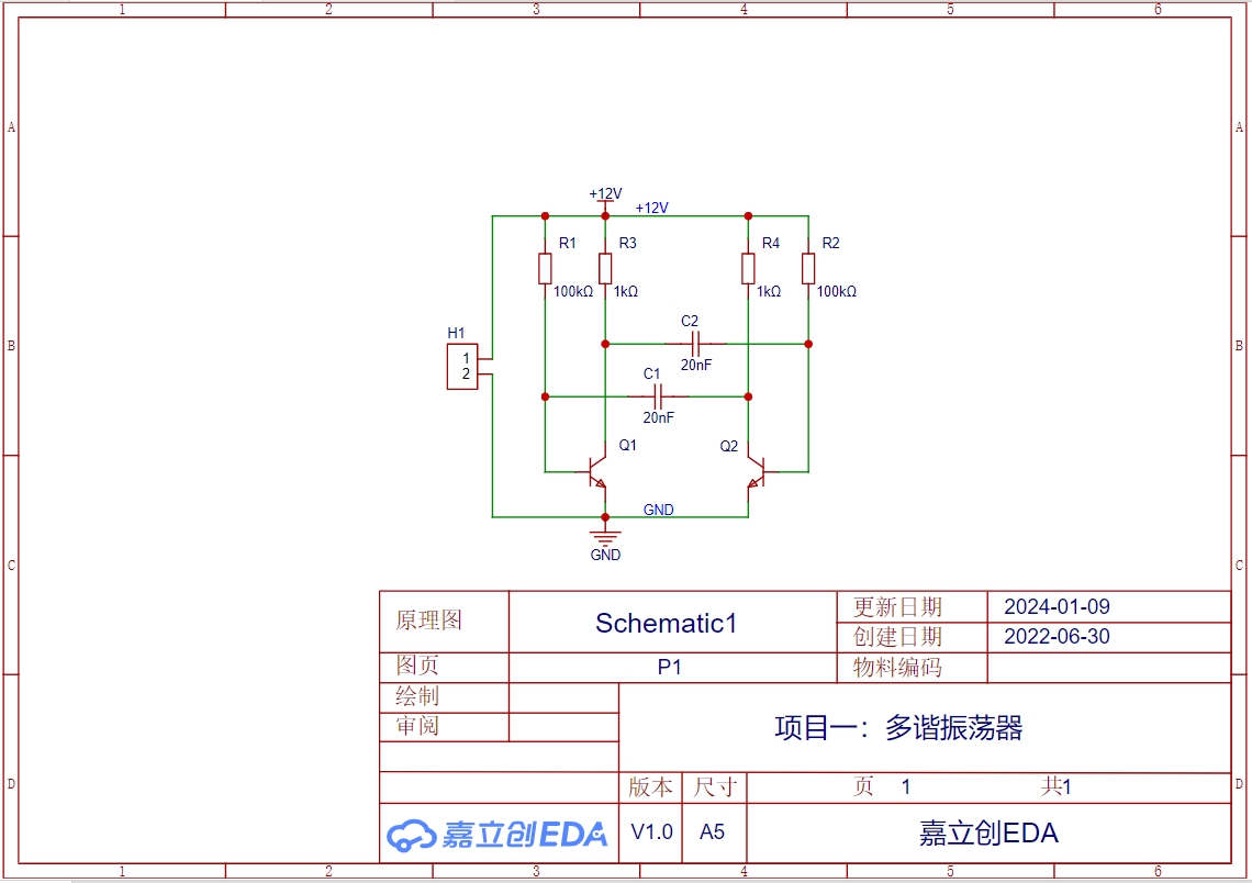
PCB,
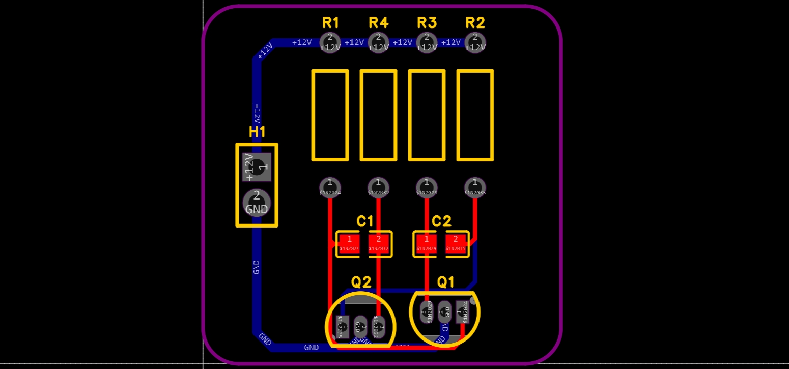
3D rendering, and

physical prototype are included .

PDF_Project 1: Multivibrator.zip
Altium_Project 1: Multivibrator.zip
PADS_Project 1: Multivibrator.zip
BOM_Project 1: Multivibrator.xlsx
96479
electronic

 All functions have been verified on the board.
  3. The DS1302 clock chip and 74HC595 chip reuse GPIO18 and GPIO19 pins (USB communication pins). If you use the simplified version of the HeZhou ESP32C3 for programming, the development board's USB automatic download function will be disabled; you will need to manually enter download mode. Using the standard version of the HeZhou ESP32C3 is unaffected.
 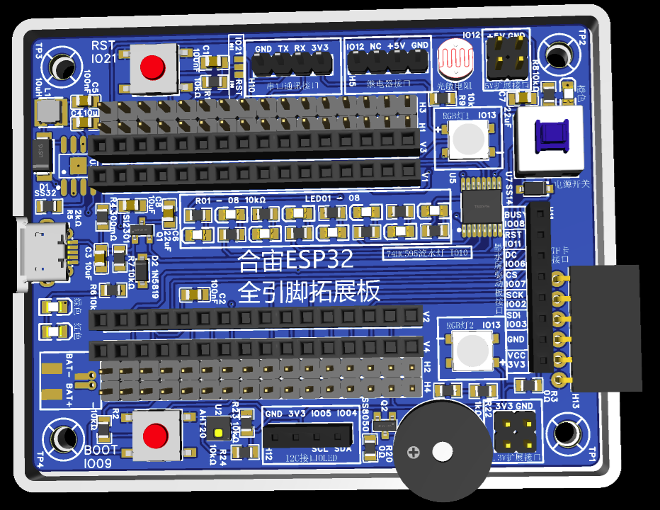 Back
Back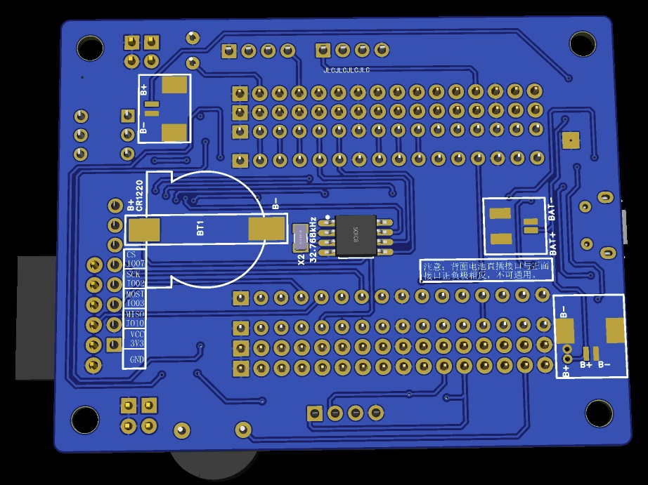


 京公网安备 11010802033920号

 2779L
2779L


