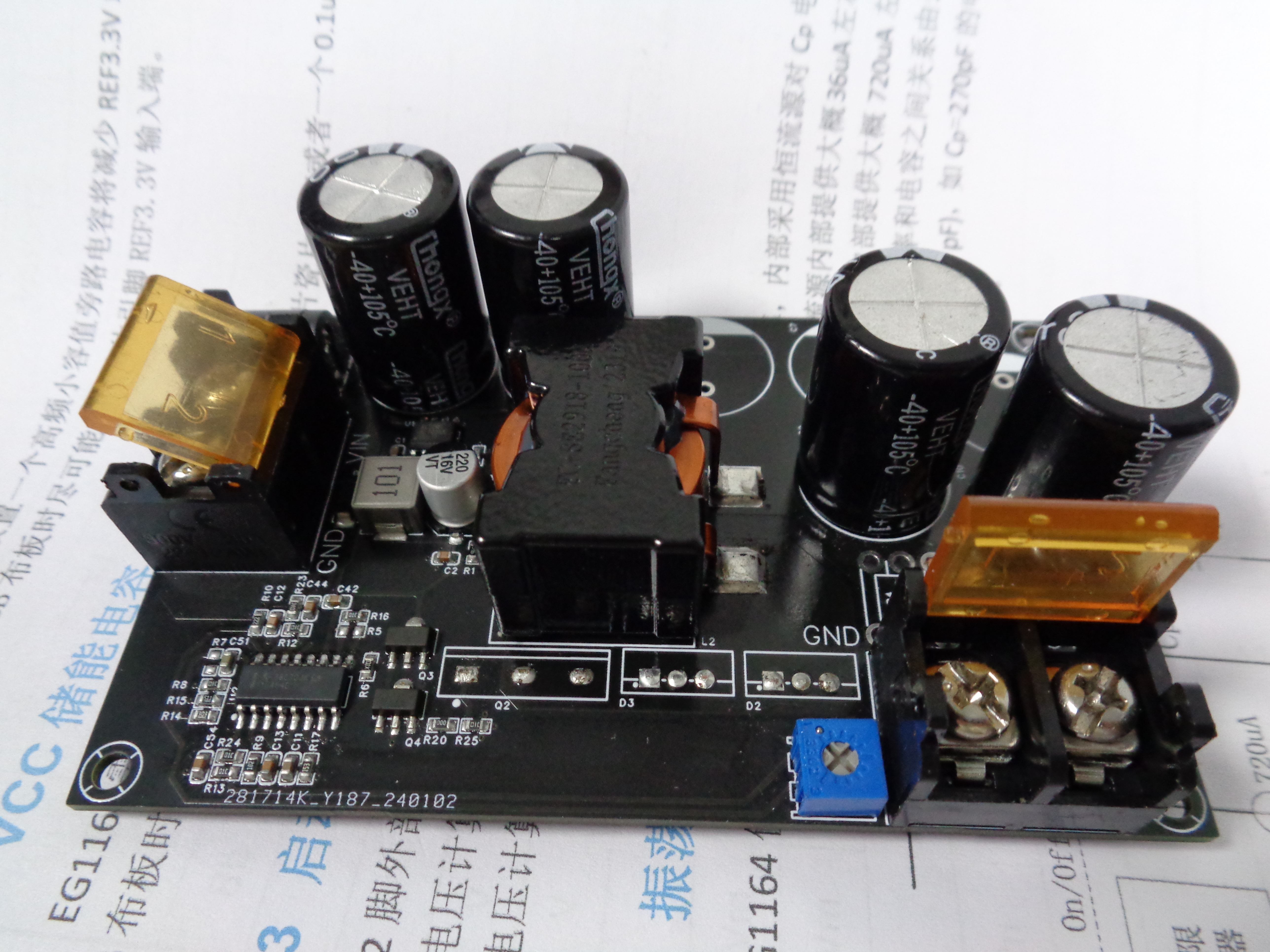
High-power boost power supply module IC based on TL494 PWM controller
: TL494
power input: 13~80V (upper limit depends on the XL7005's 80V; the input filter capacitor's withstand voltage should be higher than 80V)
Output voltage: 15~100V (upper limit limited by the soldered 100V filter capacitor)
Output current: 0~20A (related to output voltage, limited by the MOS's maximum power dissipation, heat dissipation, inductor parameters, etc.)
Due to accessory size limitations, actual load testing conditions are as follows.
VID_20240107_094428.mp4
PDF_TL494 High Power Boost Power Supply.zip
Altium_TL494 High Power Boost Power Supply.zip
PADS_TL494 High Power Boost Power Supply.zip
BOM_TL494 High Power Boost Power Supply.xlsx
96515
Motor driver board with MP2236 step-down module
A very simple motor driver expansion board based on the WashyRaspberry Pi RP2040-ZERO development board. It provides interfaces for four TMC2209/A4988/DRV8825 driver modules, supporting the TMC2209's UART mode and normal DIR/STEP mode.
Project Description
: The design is inspired by risen_c's Pico_hub 3D printer motherboard/expansion board - RP2040 - waveshare. The original author's 3D printer motherboard is exquisitely designed, but it has many features I don't use, so I simplified it. This is my first time designing a PCB. If you find any problems with the circuit or have other suggestions, please feel free to comment. Thank you.
The DC-DC section uses a Coresource MP2236GJ synchronous buck converter to convert the 12V input voltage to 5V, supporting a maximum current of 6A (I haven't tested this, but you can refer to the video BV1M14y1X7uf by Professor Sun, an engineering student on Bilibili). Replacing R6 in the schematic with a 22.1kΩ resistor will change the output voltage to 3.3V, but this requires modifying the development board's power supply circuit. I will consider using jumpers later.
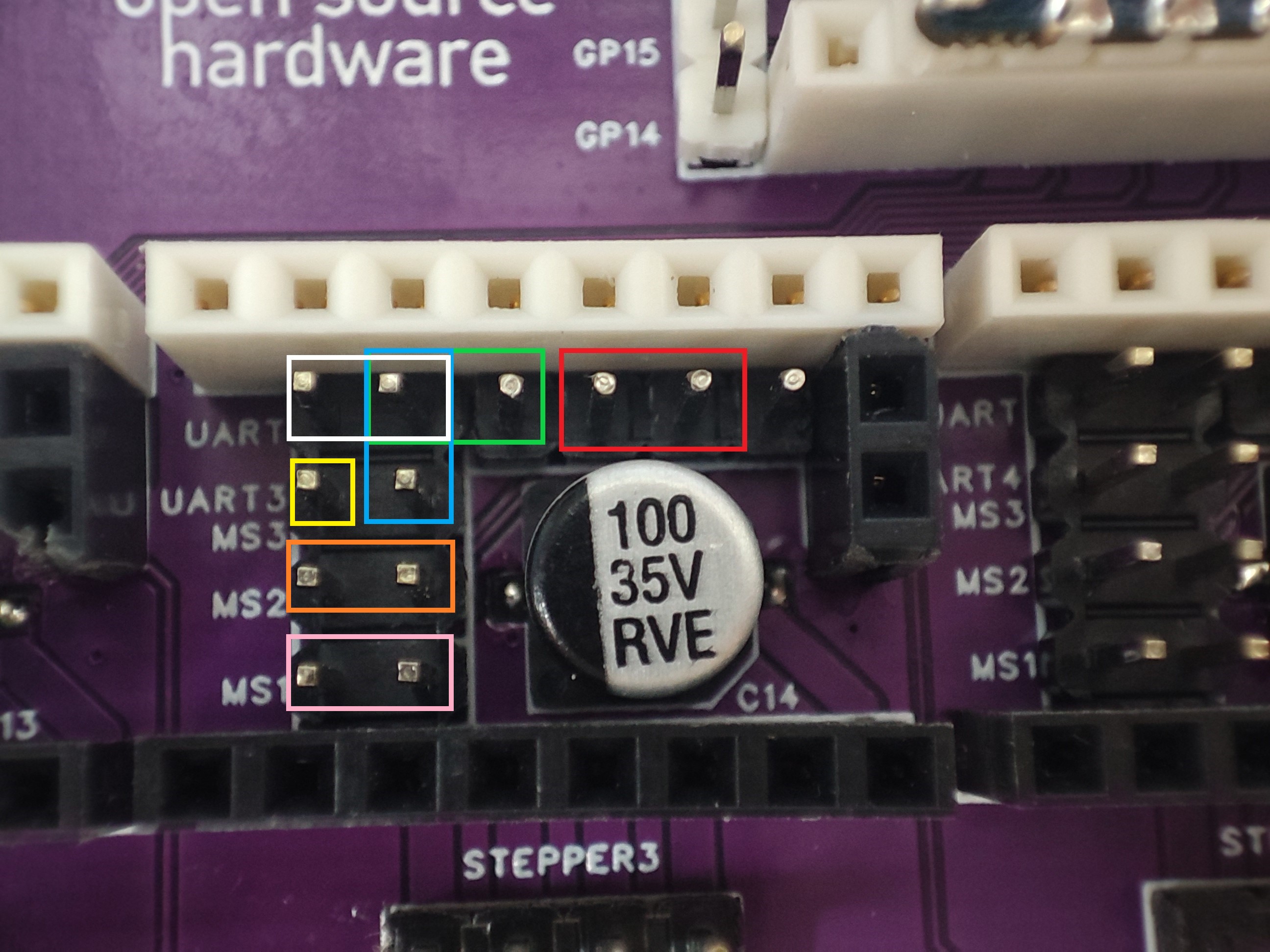
The driver board interface is compatible with Makerbase's TMC2209 driver module; the jumper usage rules differ from other driver boards. As shown in the diagram below:
Pink box: MicroStep 1, DIR/STEP mode microstepping; MS1, address 0 bit of UART single-wire addressing mode;
Orange box: MicroStep 2, DIR/STEP mode microstepping; MS2, address 1 bit of UART single-wire addressing mode;
Yellow box: No practical use in this design;
Blue box: This jumper is for the DIR/STEP mode microstepping of the A4988/DRV2588 driver module; MS3, DIR/STEP mode of TMC2209, this jumper cap is invalid;
White box: TMC2209 single-wire addressing UART mode (AUART in the schematic), all modules communicate with the microcontroller through the same interface (R/W access), the driver module address is set by setting the MS1 and MS2 jumpers;
Green box: TMC2209 parallel UART mode (PUART in the schematic), can be used to control more than 4 driver modules (I don't need it, but I reserved the interface);
Red box: CLK and PDN/UART interfaces are reserved, generally shorting them is sufficient. The jumpers on the A4988 and DRV2588 are for the Sleep and Reset pins. They don't work with the TMC2209 driver, where the CLK pin is NC. According to the Makerbase TMC2209 module layout and the TMC2209 datasheet, you can solder R5 to set an external clock for a higher baud rate.
3. Each module interface has a DIAG interface for connecting to the microcontroller, enabling sensorless homing.
Note:
There are relatively few surface-mount components, making soldering easier, but I don't know if it's because the MP2236GJ chip is easily damaged by heat; I ruined two out of three. If you want to practice, I suggest soldering only the DC-DC section first (don't poke it with a multimeter probe, a lesson learned the hard way).
There are quite a few connectors, and the GND pins are almost entirely copper-plated, increasing the difficulty of soldering.
If you're not connecting a very high-power 5V supply, you can choose an inductor with a lower rated current, which is cheaper.
Be extremely careful not to connect the driver module in the wrong direction, or it will burn out!
The RP2040-ZERO should also be able to be replaced with a development board in the same package; you can modify it yourself.
PDF_Motor driver board with MP2236 step-down module.zip
Altium_Motor Driver Board with MP2236 Buck Module.zip
PADS_Motor Driver Board with MP2236 Step-Down Module.zip
BOM_Motor driver board with MP2236 step-down module.xlsx
96517
TPS54331_Neg&Pos_Regulator
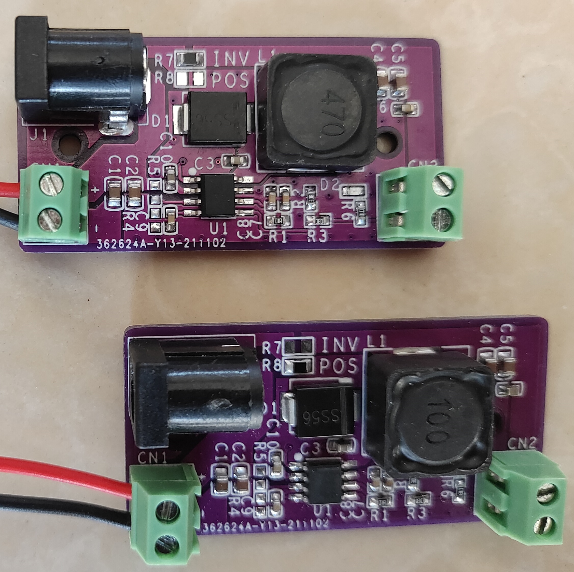
Buck positive and negative pressure module
The buck circuit based on the TPS54331 can achieve positive or negative voltage output by modifying one resistor, and can be used in series within the same system.
This has been verified.
PDF_TPS54331_Neg&Pos_Regulator.zip
Altium_TPS54331_Neg&Pos_Regulator.zip
PADS_TPS54331_Neg&Pos_Regulator.zip
BOM_TPS54331_Neg&Pos_Regulator.xlsx
96518
PCB Lantern II (Completely Open Source)
PCB lantern, eight semi-circular structures.
PCB lantern, eight semi-circular structures. 64 LEDs.
Demo video available on Bilibili: https://space.bilibili.com/476762182
. Source code attached.
DengLong2.zip
PDF_PCB Lantern II (Completely Open Source).zip
Altium_PCB Lantern II (Completely Open Source).zip
PADS_PCB Lantern II (Completely Open Source).zip
96519
PCB Lantern 1 (Completely Open Source)
Make a lantern using a PCB, with an eight-lobed watermelon rind structure.
Make a lantern using PCBs, with an eight-segment watermelon rind structure, consisting of 26 PCBs (8+8+8+2=2).
It has 48 LEDs (6*8=48). The actual effect is mediocre; it looks a bit like the octopus burger from Octonauts.
A demo video can be found on Bilibili: https://space.bilibili.com/476762182
. The source code is attached.
DengLong1.zip
PDF_PCB Lantern 1 (Completely Open Source).zip
Altium_PCB Lantern 1 (Completely Open Source).zip
PADS_PCB Lantern 1 (Completely Open Source).zip
96520
Small-size DC-DC step-down module
A 14mm x 8.8mm DC-DC step-down module
The

DC-DC step-down module
is only 14mm × 8.8mm in size, suitable for use in compact spaces and can be soldered onto a PCB.
I used the ME3116, and tested it with a 30V input and a normal 5V/0.75A output, with the board getting slightly warm.
For different input/output specifications, simply replace the chip with one that has the same pinout.
It is recommended to solder an SOD-123F TVS diode at the Vin pin of the board. Testing with a 30V TVS diode showed sparks when plugging and unplugging at 12V, but it did not cause damage.
Inductors such as 1210, SMD2.5×2×1.2, and 0806 can be used.
Replaceable chips (currently found):
Input
Input
Input
Input Input
Schottky. Recommended model:
MS2A40LWS supports a maximum output of 2A
. Output ≤1A: SS14 is sufficient.
Module description:
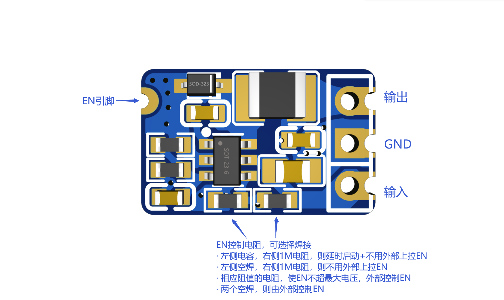
TVS diode soldered on the side.

PDF_Small-sized DC-DC step-down module.zip
Altium Small-Size DC-DC Step-Down Module.zip
PADS Small-Size DC-DC Step-Down Module.zip
BOM_Small Size DC-DC Step-Down Module.xlsx
96521
electronic


 京公网安备 11010802033920号

 UF4001


