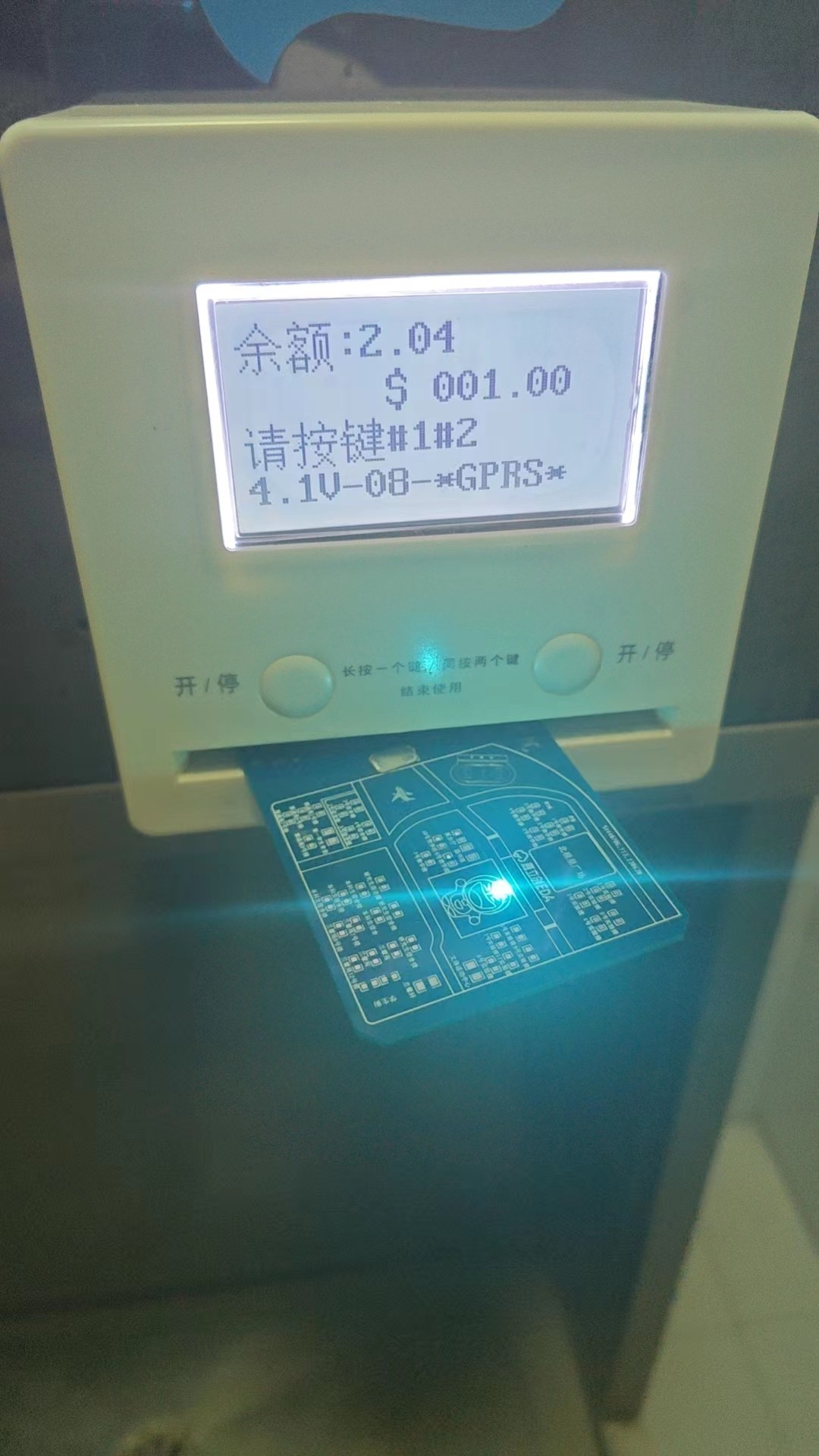
The PCB design includes a coil, on which water card and bath card chips can be soldered for normal use.

PDF_Shanxi University of Science and Technology Campus Card.zip
Altium_Shanxi University of Science and Technology Campus Card.zip
PADS_Shanxi University of Science and Technology Campus Card.zip
BOM_Shanxi University of Science and Technology Campus Card.xlsx
96786
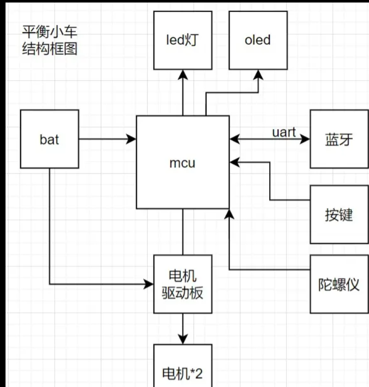
Balance car with TB6612 drive
This project involves building a self-balancing scooter using a GD470.
This project is a balance car built using the Liangshanpai development board. I integrated all the necessary modules onto one board, plus a TB6612 driver. This driver was developed after researching a module purchased by someone else, and it has been verified to be usable. The use of the hole in the disc works without any problems. This project uses a 0.96-inch screen, an ultrasonic module, a self-made driver module, a buzzer, a Bluetooth module, an MPU6050 module, and grayscale to achieve line tracking and remote control functions.
Next, I'll explain the modules I used, my learning methods, and the process. First, for the 0.96-inch screen,
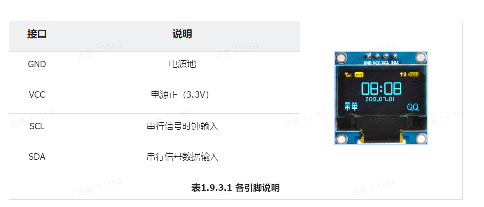
you mainly need to learn IIC, and then briefly learn interface graphic design.
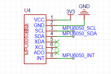
The MPU6050 is used for balance, reading the accelerometer measurements (raw values) for the X/Y/Z axes, and it also
transmits data via IIC.
Then there's the ultrasonic module for distance measurement and grayscale line tracking. I didn't include grayscale because I didn't have it.
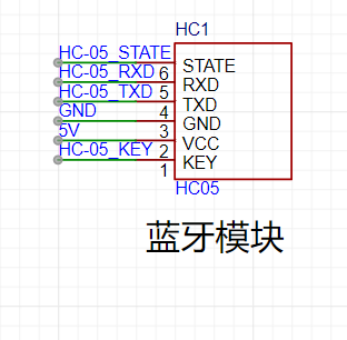
Because long-distance control is required, Bluetooth control is necessary. The HC-05 Bluetooth module is a master-slave integrated module, connecting via UART and MCU. The car is controlled via a mobile phone. Note that it needs to be powered on at 3.3V, and RXD and TXD need to be cross-connected with a baud rate of 38400.
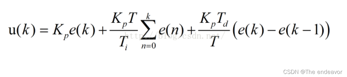
Regarding the learning and application of PID, we first need to know its uses. Secondly, the uses of PID are: 1. Basic requirements for automatic control systems: stability, accuracy, and speed: Stability (P and I decrease system stability, D increases system stability): In a balanced state, after a disturbance, the controlled variable can reach a certain stable state after a period of time; Accuracy (P and I increase steady-state accuracy, D has no effect): The steady-state error of the system when it is in a steady state; Speed (P and D increase response speed, I decrease response speed): The system's requirements for dynamic response. Generally measured by the length of the transition time. 2. Stability: When the system is in a balanced state, after a disturbance, if the system output can recover to the original steady-state value, then the system is stable; otherwise, the system is unstable. 3. Dynamic Characteristics (Transient Characteristics, caused by system inertia): The dynamic response curve of the system output when a given quantity is suddenly applied (or the load changes suddenly). This includes delay time, rise time, peak time, settling time, overshoot, and number of oscillations. Typically: a. Rise time and peak time are used to evaluate the system's response speed; b. Overshoot is used to evaluate the system's damping degree; c. Settling time reflects both response speed and damping degree.
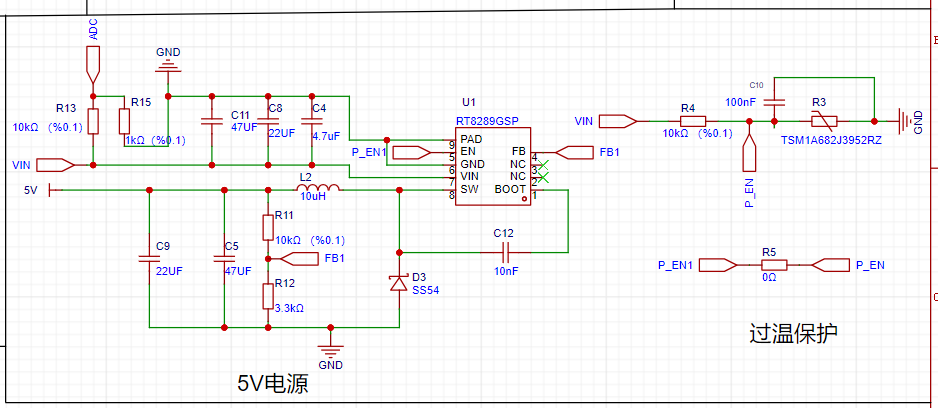
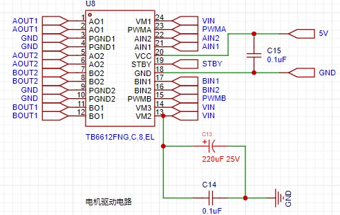
Next is the TB6612 driver module, which uses a 12V input and has outputs of 12V, 5V, and 3.3V. It also features over-temperature protection, which is truly impressive. This system includes
a brushless motor drive circuit
with LED power indicator
and an OLED display connected via IIC and MCU, primarily displaying PID parameters. It also includes
a BAT (Battery Unit) 18650 battery,
an MCU (GD32F470)
, and a Bluetooth module (HC-05 master-slave integrated module connected via UART and MCU). The system allows control of the vehicle's
buttons, power switch, and PID adjustment via a mobile phone
. A custom-made motor drive board (TB6612FNG) drives two motors (
*2) with encoders and a top
gyroscope (MPU6050)
. Hope this is helpful.
video_231212_001836.mp4
Balance bike.zip
PDF_Balanced Car with TB6612 Driver.zip
Altium self-balancing scooter with TB6612 driver.zip
PADS_Balance Car with TB6612 Driver.zip
BOM_Balanced Car with TB6612 Driver.xlsx
96787
Separating the serial port from Type-C does not affect the functionality of Type-C.
The female Type-C connector is directly connected to the male connector (CC1, CC2, and DPDM), and then the male connector's SBU1/SBU2 is used as a serial port.
Currently, it can be used on M28K (an edge computing development board based on RK3528) and H28K (a software router), making it convenient to use the serial port when the shell is installed. In Type-C, if the alt function is not used, then the SBU1 and SBU2 lines are idle. Here, they are connected to the processor's debug serial port.
DSC00608.JPG
DSC00609.JPG
DSC00610.JPG
DSC00602.JPG
DSC00605.JPG
WeChat screenshot_20231213100626.png
PDF_Separating the serial port from Type-C without affecting Type-C functionality.zip
Altium - Separating the serial port from Type-C without affecting Type-C functionality.zip
PADS - Separating the serial port from Type-C without affecting Type-C functionality.zip
The BOM (Bill of Materials) separates the serial port from the Type-C port without affecting the functionality of the Type-C port.xlsx
96788
ESP32-S3-BOX_Lite
The ESP32-S3-BOX-Lite is an AIoT application development board equipped with the ESP32-S3 SoC. It provides users with a platform to develop and control smart home devices based on functions such as voice assistants, sensors, and smart Wi-Fi gateways.
ESP-BOX is Espressif Systems' next-generation AIoT application development platform. The ESP32-S3-BOX-Lite is the corresponding AIoT application development board, equipped with the AI-accelerated ESP32-S3 Wi-Fi + Bluetooth 5 (LE) SoC
. It provides users with a platform to develop and control smart home devices based on functions such as voice assistants, sensors, infrared controllers, and smart Wi-Fi gateways. The development board supports offline voice interaction by default. Through Espressif's rich SDK and solutions, users can easily build diverse applications such as online and offline voice assistants, smart voice devices, HMI human-machine interaction devices, control panels, and multi-protocol gateways.

Features include
dual microphones supporting far-field voice interaction,
high wake-up rate offline voice wake-up,
high recognition rate offline Chinese and English command word recognition
, dynamically configurable 200+ Chinese and English command words,
continuous recognition and wake-up interruption ,
flexible and reusable GUI framework
, end-to-end one-stop access to the cloud platform
Pmod™, compatible interfaces supporting multiple peripherals .
Usage Guide:
Upon first receiving the BOX series development board, you can refer to the initial use operation guide;
to experience the offline voice assistant function, you can refer to the offline voice recognition;
to experience more user-friendly voice interaction, you can refer to the continuous voice recognition;
to set unique voice command words through the mobile APP, please refer to the ESP-BOX APP operation guide;
to see the product exploded view and disassembly instructions, please refer to the disassembly tutorial;
to understand the development board hardware and interface details, please refer to the hardware overview;
to use the latest firmware version, please refer to the firmware update instructions.
Development Guide:
The ESP-BOX integrates commonly used components in AIoT development, which you can use to build your own applications.
Get Started Quickly:
Step 1. If you are new to ESP-IDF development, it is recommended to first browse the ESP-IDF Programming Guide to understand the open-source drivers and components provided by Espressif.
Step 2. Next, you can read the ESP-IDF (release/v4.4 or release/v5.0) environment setup guide step by step to complete the development environment setup.
Step 3. Use the command `git clone --recursive https://github.com/espressif/esp-box.git` to download the code for this project, and then you need to switch the ESP-IDF version to the specified version.
Step 4. Try it out: You can try building and flashing a new sample program.
Step 5. Go further: You can read the ESP-BOX technical architecture description to learn more about the technical details.
Step 6. In-depth development: You can read the ESP Speech Recognition Application Development Guide, the ESP RainMaker Programming Guide, and the LVGL UI Interface Development Quick Overview.
Step 7. Expanding functionality: You can read the introduction to the Pmod™ compatible interfaces of the development board and the ESP-IDF API Reference Manual to develop drivers for more extended devices.
Related Videos:
ESP32-S3/ESP-BOX Teams Up with ChatGPT to Create a 4-in-1 Smart Speaker
[Espressif Solution] | ESP32-S3-BOX Empowers Espressif Smart Conference Rooms;
"Wenxin Yiyan" Chatbot Based on ESP32-S3-BOX-Lite;
Unleashing the Power of OpenAI and ESP-BOX: A Guide to Fusing ChatGPT with Espressif SOCs
; OpenAI Component | Accelerating the Integration of OpenAI APIs in Projects;
More Exciting Demo Videos; Related Materials:
2.4-inch 320 x 240 LCD (without touchscreen; for screen interaction, please type esp32_s3_box_lite_Button); PCB;
Screen Procurement Link;

Shell Structure
3D Printing Source Files
PDF_ESP32-S3-BOX_Lite.zip
Altium_ESP32-S3-BOX_Lite.zip
PADS_ESP32-S3-BOX_Lite.zip
BOM_ESP32-S3-BOX_Lite.xlsx
96789
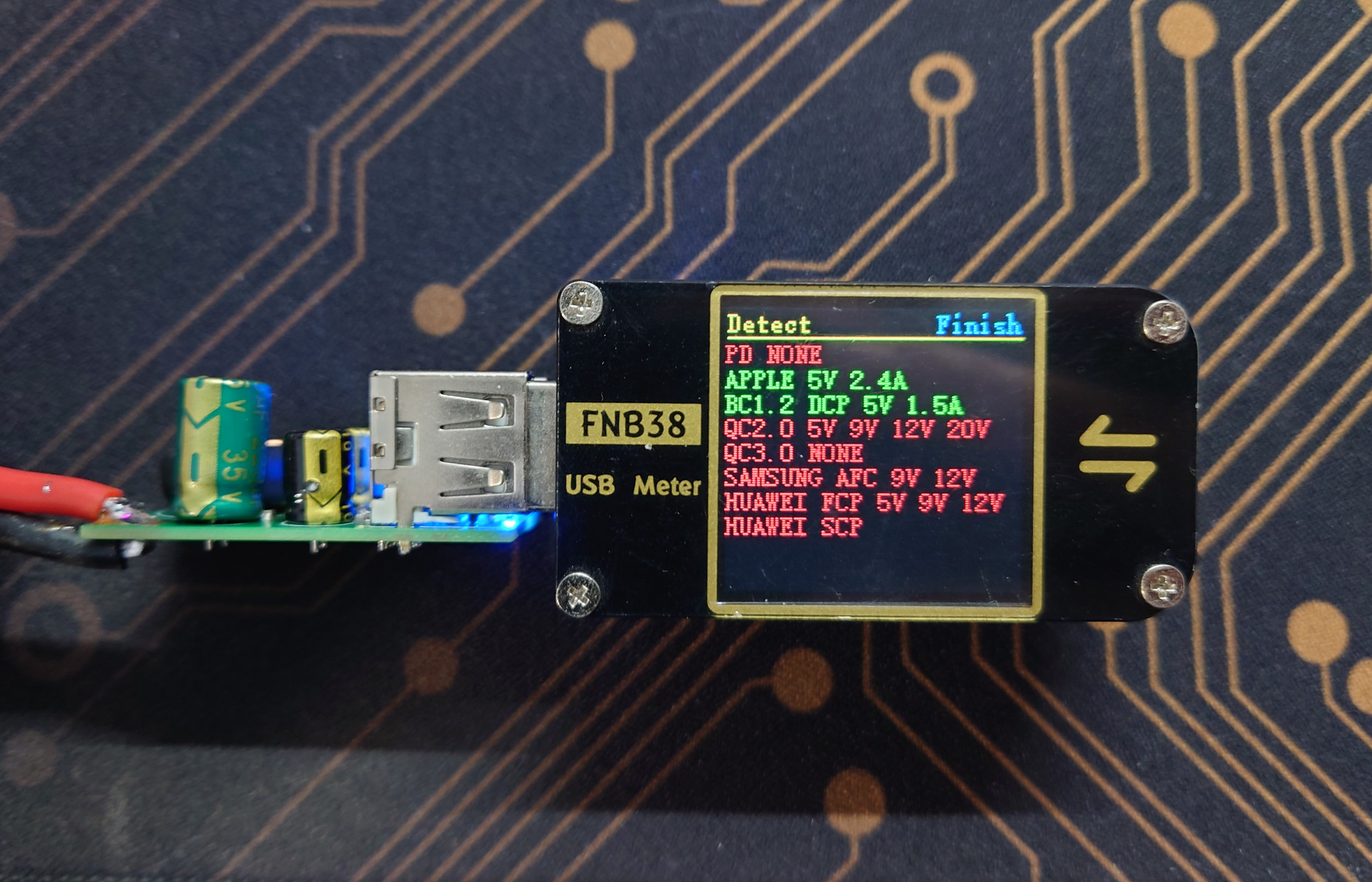
CX8850 step-down module verification board
The CX8850 is a simple-to-use, high-performance, stable and reliable constant voltage/constant current step-down DC-DC converter.
● Input voltage up to 4.75V-40V
● Built-in 20mΩ High-side NMOS
● Built-in 20mΩ Low-side NMOS
● Supports 4A continuous output current
● Supports 98% duty cycle
● Output voltage and current adjustable (2.5V-20V)
● Constant current accuracy ±6%
● Constant voltage accuracy ±2% (VFB=1.0V)
● No external compensation required
● 110kHz fixed switching frequency
● Cable voltage drop compensation
● Short circuit protection (SCP), overheat protection (OTP), overvoltage protection (OVP)
● Built-in SW cycle-by-cycle detection mode to avoid short circuit damage to the RSENT current-limiting resistor.
● SOP-8L package
, 24V input, 5V output, 2.4A test passed,
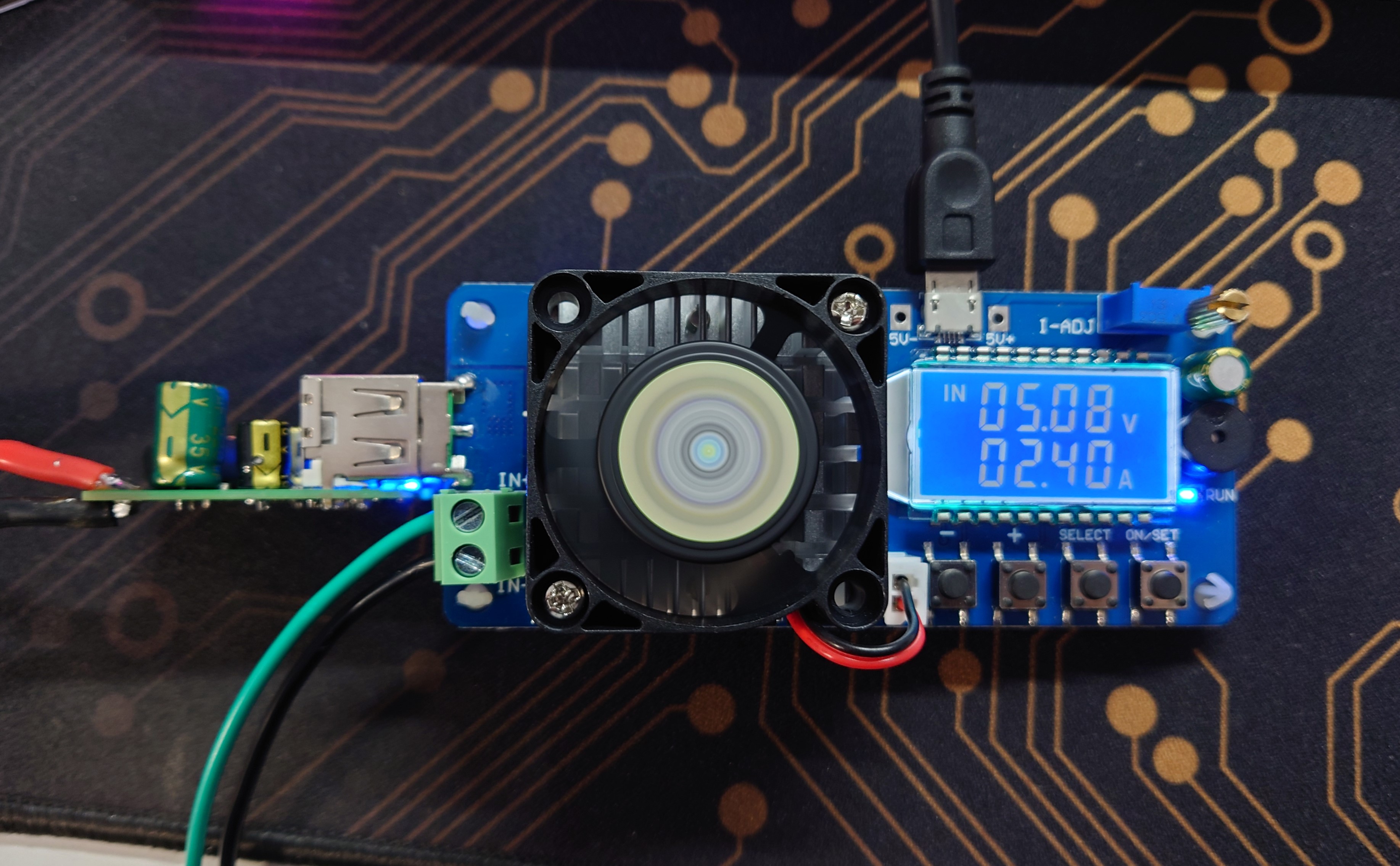
protocol chip recognition is normal.
PDF_CX8850 step-down module verification board.zip
Altium_CX8850 step-down module verification board.zip
PADS_CX8850 step-down module verification board.zip
BOM_CX8850 step-down module verification board.xlsx
96790
3D printing motor drive module interface to RJ45 interface to servo interface
The 3D printer replaces the stepper motor module, with an RJ45 interface, providing enable, direction, step, and other alarm signals. The Z zero-point signal is currently unused.
This is a custom-made adapter board for connecting servo motors via Ethernet cable. The standard Ethernet cable crimping sequence is T586B: white-orange-orange-white-green-blue-white-blue-green-white-brown-brown. The other end connects to the SCSI 50 servo connector. I'm using a Panasonic A5 servo motor.
The wiring is as follows: color, function, SCSI terminal number:
white-orange = pulse -, 4 orange = pulse +, 3
white-green = direction -, 6 green = direction +, 5
blue-white = Z phase, 19 blue = alarm, 37
white-brown = common negative, servo enable negative 29, the last two are optional (Z phase negative 25, alarm negative 36),
brown = 24V (servo enable), 7
PDF_3D Printing Motor Driver Module Interface to RJ45 Interface - Servo Interface Converter.zip
Altium 3D Printing Motor Driver Module Interface to RJ45 Interface - Servo Interface Converter (zip file)
PADS 3D Printing Motor Driver Module Interface to RJ45 Interface - Servo Interface Converter (zip file)
BOM_3D Printing Motor Driver Module Interface to RJ45 Interface - Servo Interface Converter.xlsx
96791
Deceptive Dice
The Baby-Cheating Dice (An electronic dice with hidden cheating features)
The "Trick Dice" (an electronic dice with a hidden cheat function)
is normally a regular electronic dice, but it has a hidden cheat function. If you roll a 1, 3, 1, 4 in sequence, and then land on the cheat number, the next roll will always be the cheat number. It can be used to fool children.
A demonstration video can be found on Bilibili.
[Trick Dice - Bilibili] https://b23.tv/gc1DQ0X
Second Generation: https://www.bilibili.com/video/BV1tt4y1f7kG/
Improved Charging Stand: https://www.bilibili.com/video/BV1ScydYdEgj/
Charging dock case.STL
PDF of the "Trick-or-Treat Dice" game, source code uploaded. zip
Altium_Trick Dice, source code uploaded. zip
PADS_Trick-or-Treat Dice, source code uploaded. zip
BOM_Liar's Dice, source code uploaded.xlsx
96792
21 Shenggong LHS-Multifunctional Power Module
A multi-functional 12V to multi-gradient adjustable amplitude power supply module built using voltage regulator chips such as LM7805, LM2596R, and AMS1117-3.3.
In this project, I redesigned a 12V to multi-gradient, adjustable voltage power supply module, referencing the design of @不想写代码的我的设计.
This module utilizes voltage regulator chips such as LM7805, LM2596R, and AMS1117-3.3 to convert the 12V signal into a multi-functional power supply module capable of outputting 5V, 3V3, and 1V~12V adjustable voltage signals. The module can be used with a battery to input a stable 12V voltage signal via a power connector. It then uses these voltage regulator chips to convert the 12V signal into an adjustable voltage signal with integrated outputs of 5V, 3V3, and 1V~12V.
This module can be used in various electronic design projects requiring multi-gradient voltage signal sources such as 3V3 and 5V.
PCB_Multifunctional Power Supply Module_2023-12-10.pdf
SCH_Multifunctional Power Module_2023-12-10.pdf
video_20231210_122618.mp4
PDF_21 Shenggong LHS-Multifunctional Power Module.zip
Altium_21 Biotech LHS-Multifunctional Power Module.zip
PADS_21 Shenggong LHS-Multifunctional Power Module.zip
BOM_21 Shenggong LHS-Multifunctional Power Module.xlsx
96793
electronic


 京公网安备 11010802033920号

 MI-P7KW-IYW


