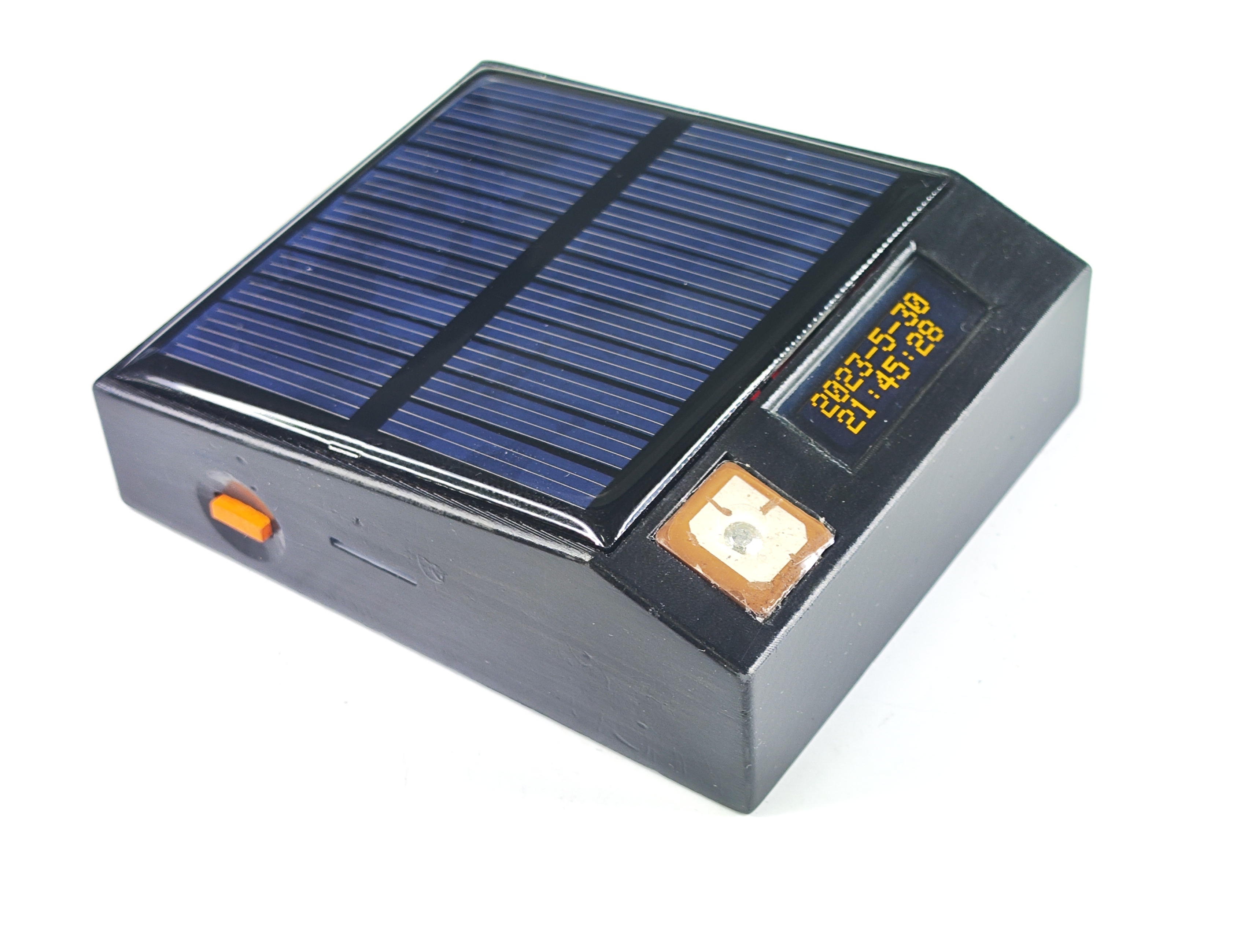
GPS + Electronic Compass Positioning Device Project Introduction: This project was developed to address positioning and navigation in the wild without network coverage. Initially, the STM32F103RCT6 development board was used for overall project development. After comparison and selection, the lower-cost STM32F103C8T6 was chosen as the main controller. An ATGM336H GPS positioning module and a QMC5883L magnetometer are used. The main controller collects information such as time, latitude and longitude coordinates, altitude, speed, and azimuth, and displays it on a 0.91-inch OLED screen. The system adopts a low-power design, with a built-in 320mA/h lithium battery. An external solar panel enables all-weather positioning without an external power source. The system is designed so that a single button connects both the MCU main controller and the DC power chip, allowing for power on/off with a long press and display interface switching with a short press, reducing operational complexity and minimizing the risk of system failure. When used with a paper map, the device can perform functions such as time viewing, positioning and navigation, orientation finding, and altitude marking.
Note: This version was completed in just 7 days from project initiation, so there are still quite a few bugs. This version is for reference only. Wait for the sequel.
A four-channel lithium battery charging module.
I. Design Background
This charging module project originated from a classmate's Zhengdian Atom drone, which required frequent and lengthy charging cycles. This sparked the idea of creating a charger. Additionally, I'm planning to build a five-person drone for fun, and the battery power supply is a good first step.
II. Design Summary
Lithium batteries have specific charging rules; the charging current cannot exceed 0.5-1.5 times the battery capacity. My primary rechargeable battery capacity is no more than 500mAh, typically around 300-400mAh. Therefore, the TP4059 is a suitable choice:
• Reverse polarity protection for lithium batteries; • Programmable charging current up to 600mA;
• Constant current/constant voltage operation with thermal regulation to maximize charging rate without overheating; • Direct charging of single lithium-ion batteries from a USB port; • 4.2V preset charging voltage accuracy of ±1%; • Maximum input voltage up to 9V;
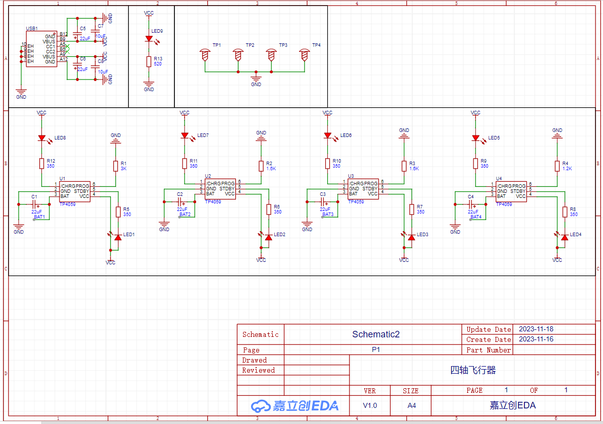
VI. Hardware Circuit Composition
The hardware circuit mainly consists of four TP4059 chips, several filter capacitors, indicator LEDs, current setting resistors, and current limiting resistors. It offers three charging current settings: 300mAh, 500mAh, and 600mAh. The main circuit principle is shown in the diagram below.
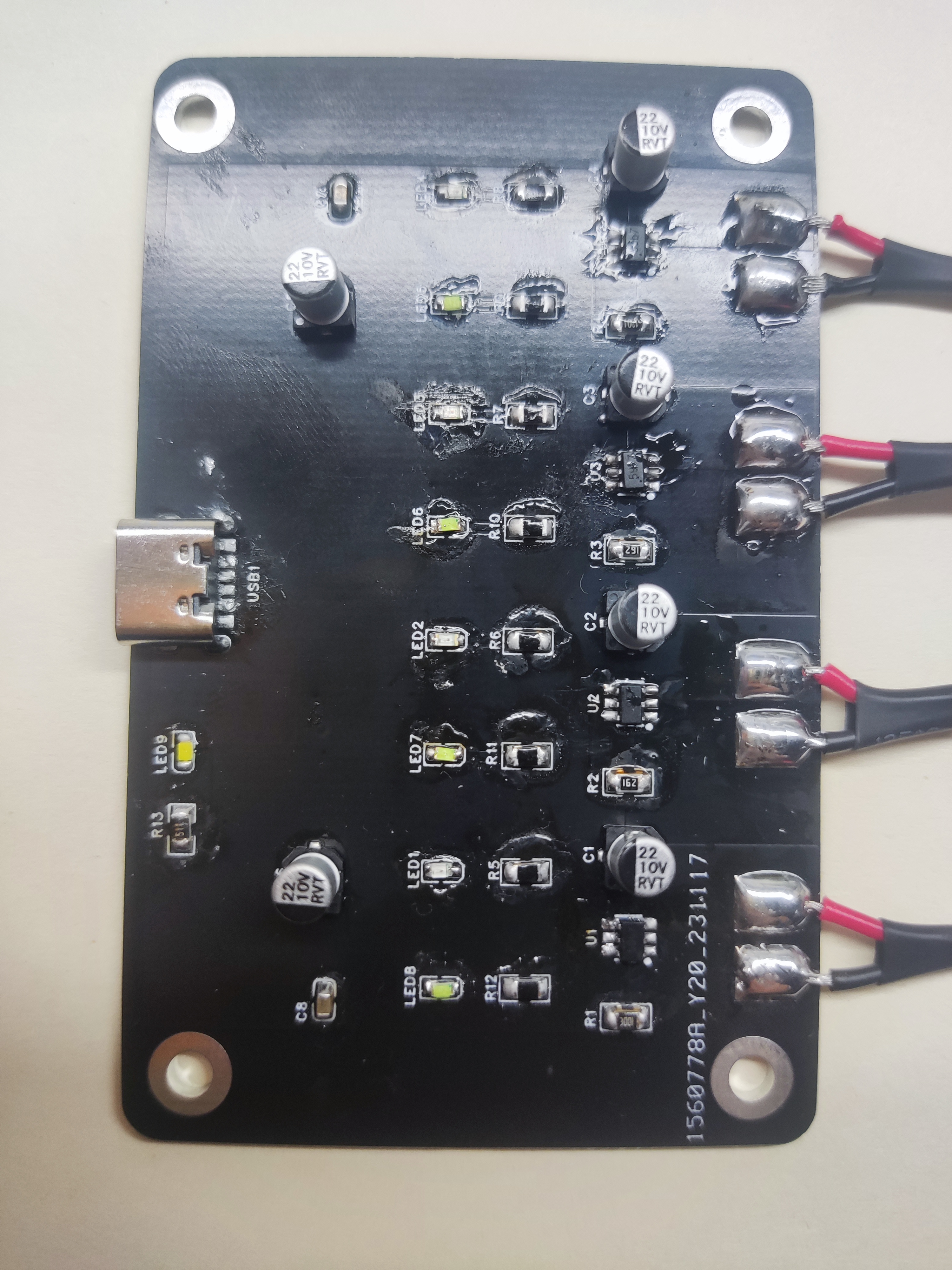
VIII. Physical Demonstration
IX. Precautions
The main thing to note is the battery's positive and negative terminals; avoid problems at the connection points. Although there is reverse connection protection, please note that if the battery already has a voltage greater than 4V, it will not enter the charging state when you try to charge it.
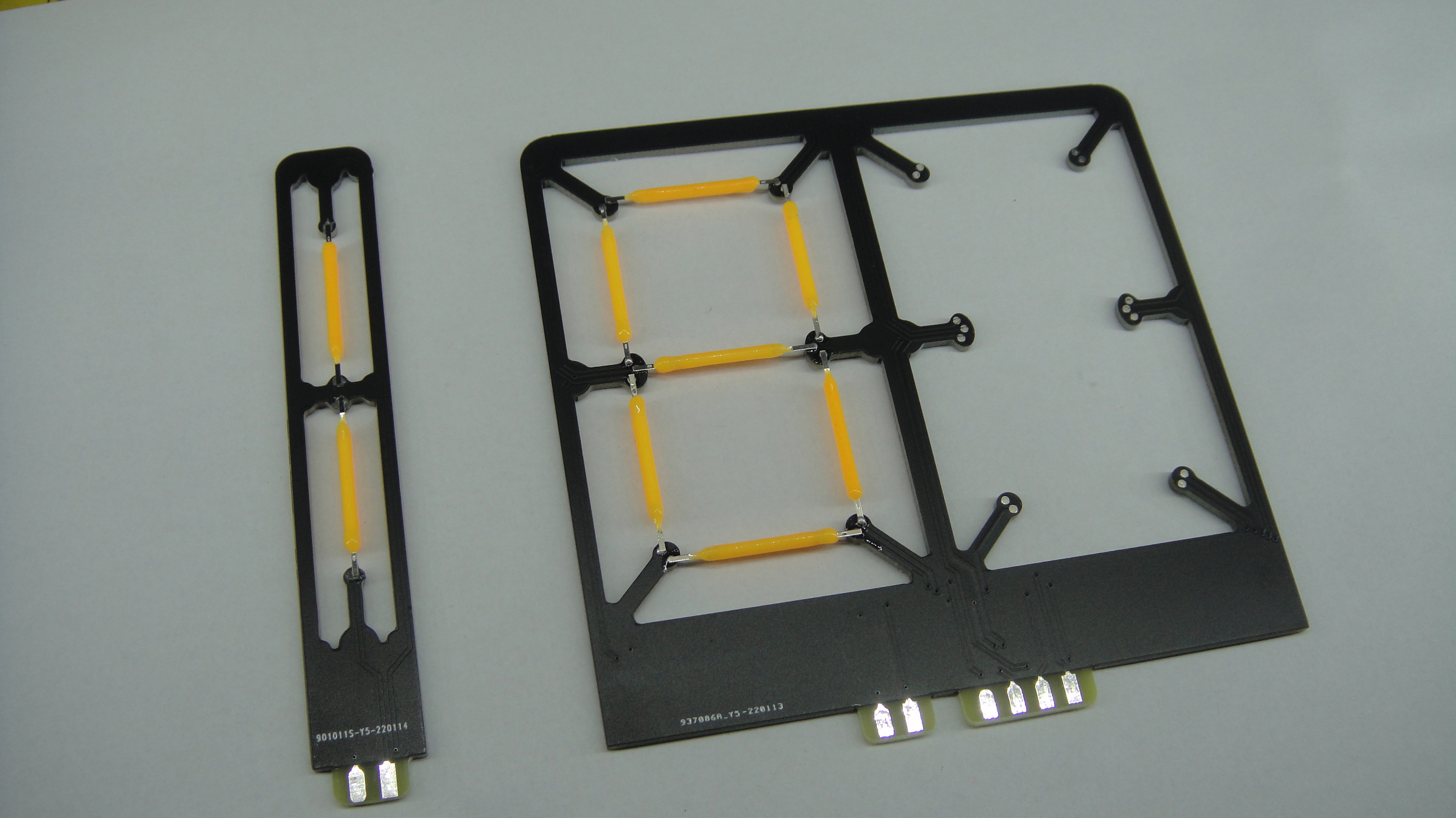
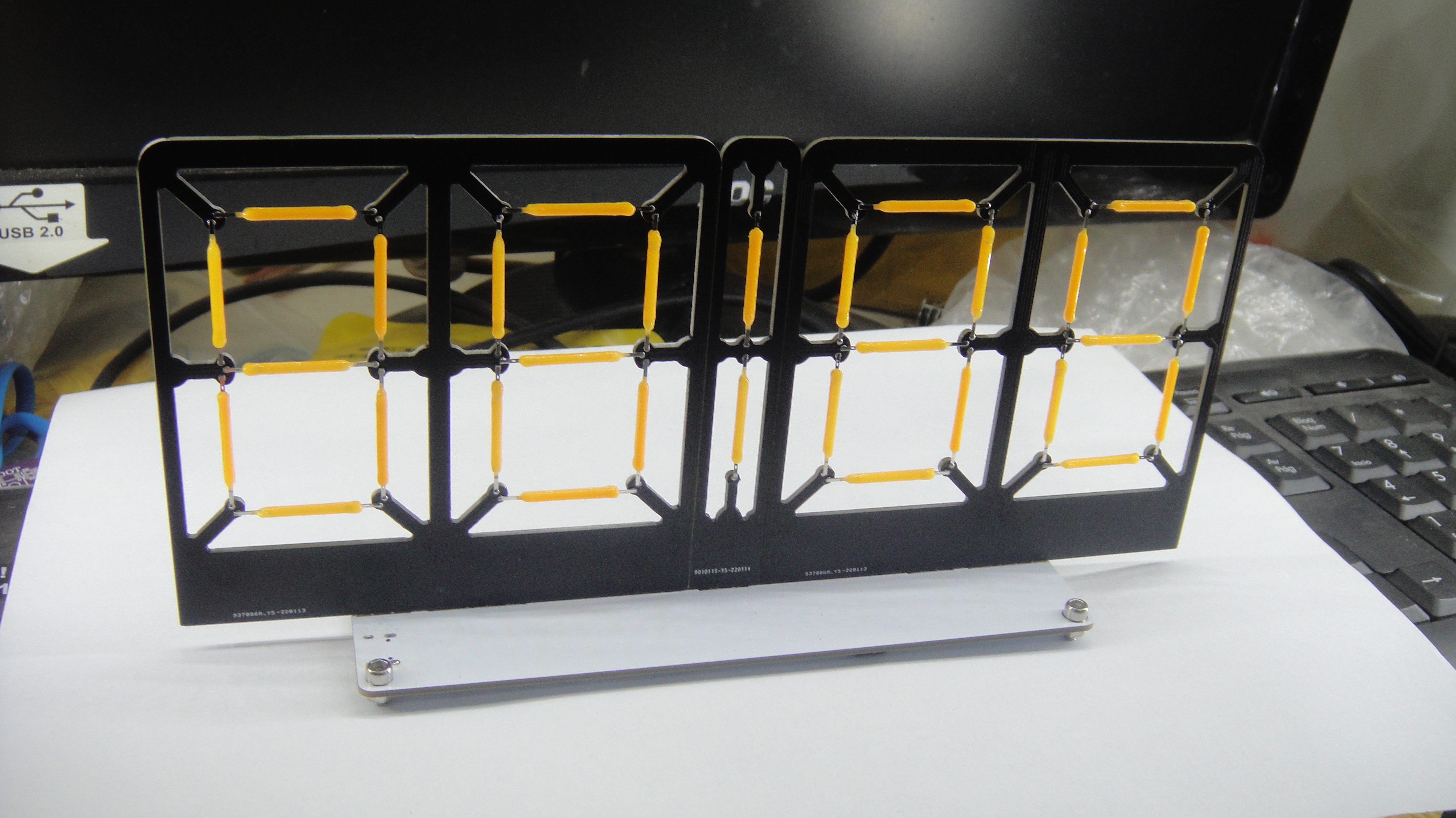
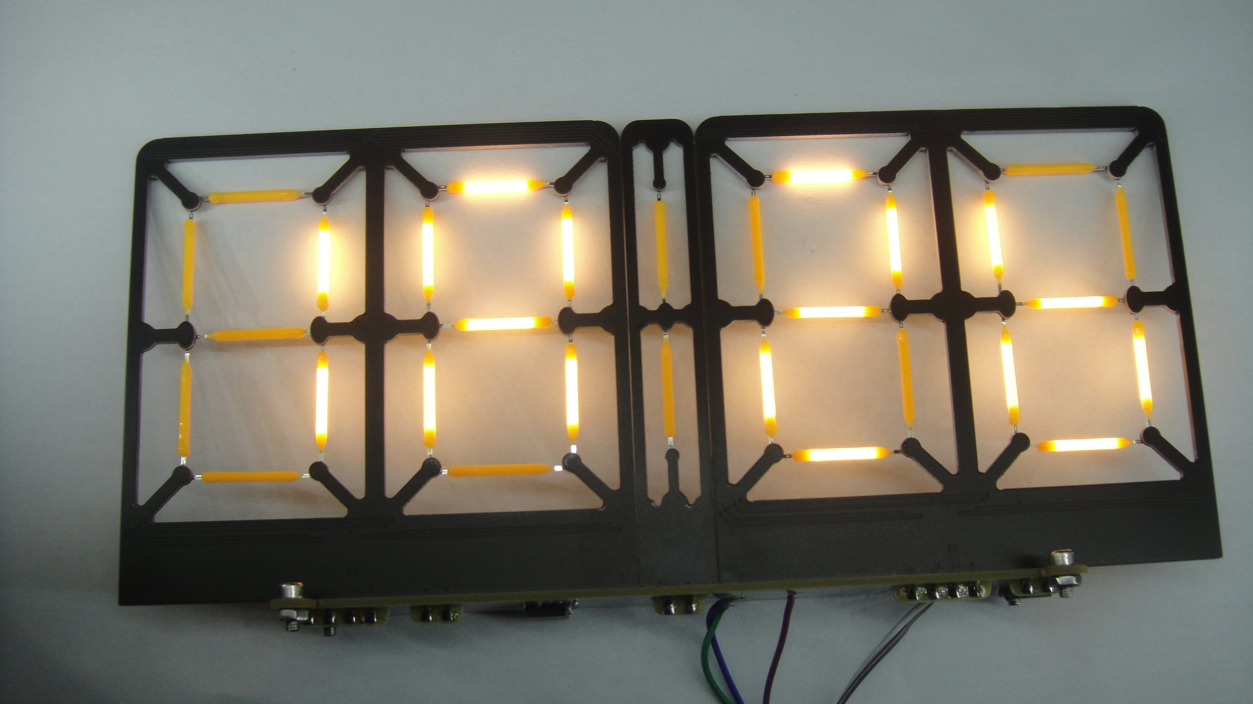
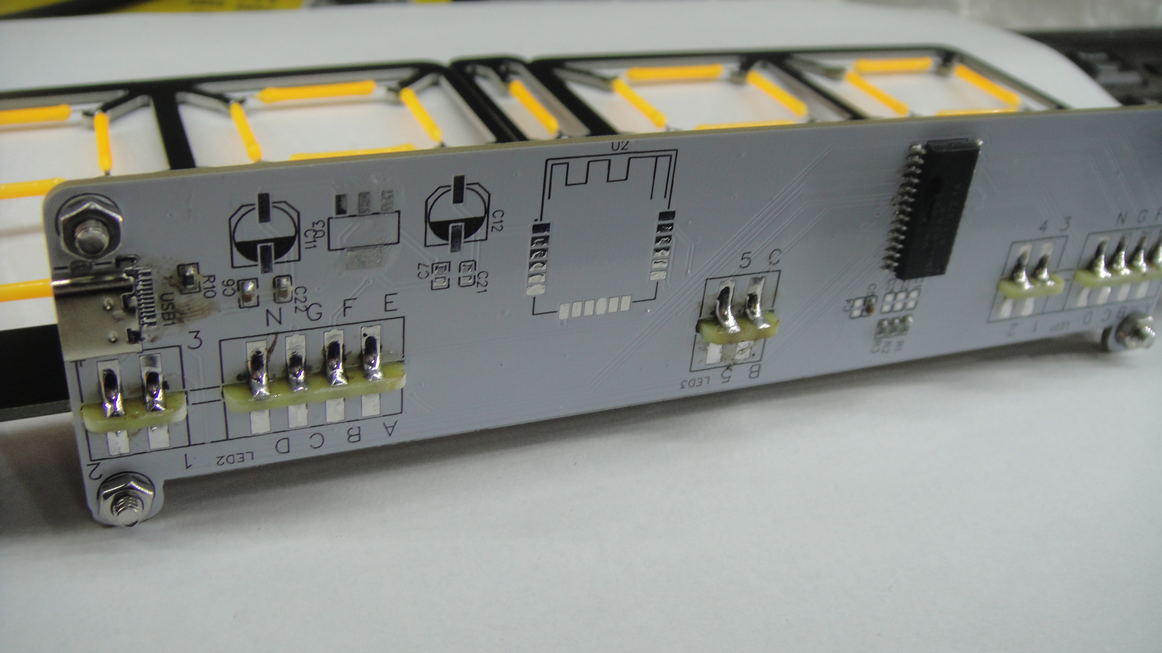
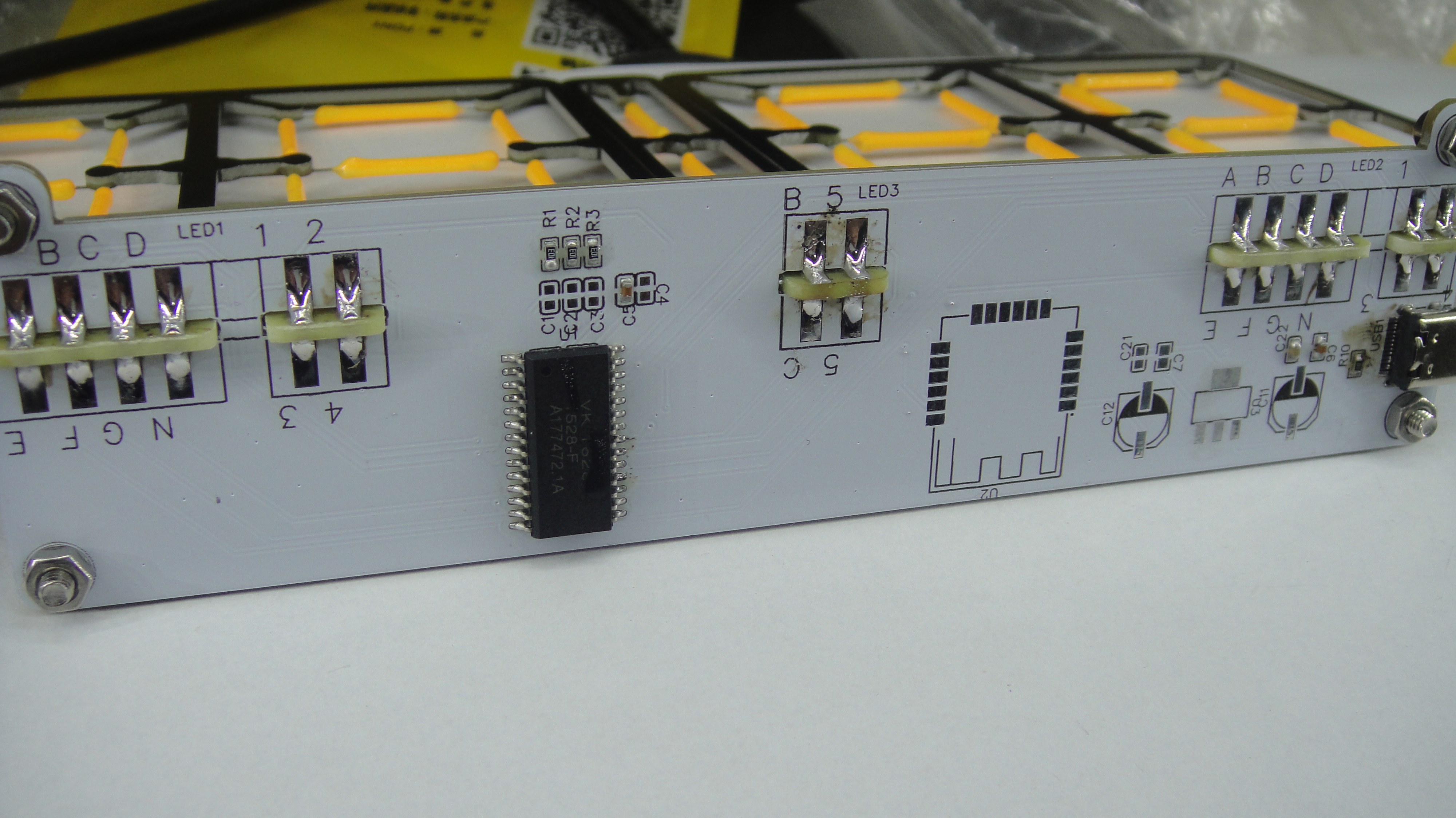
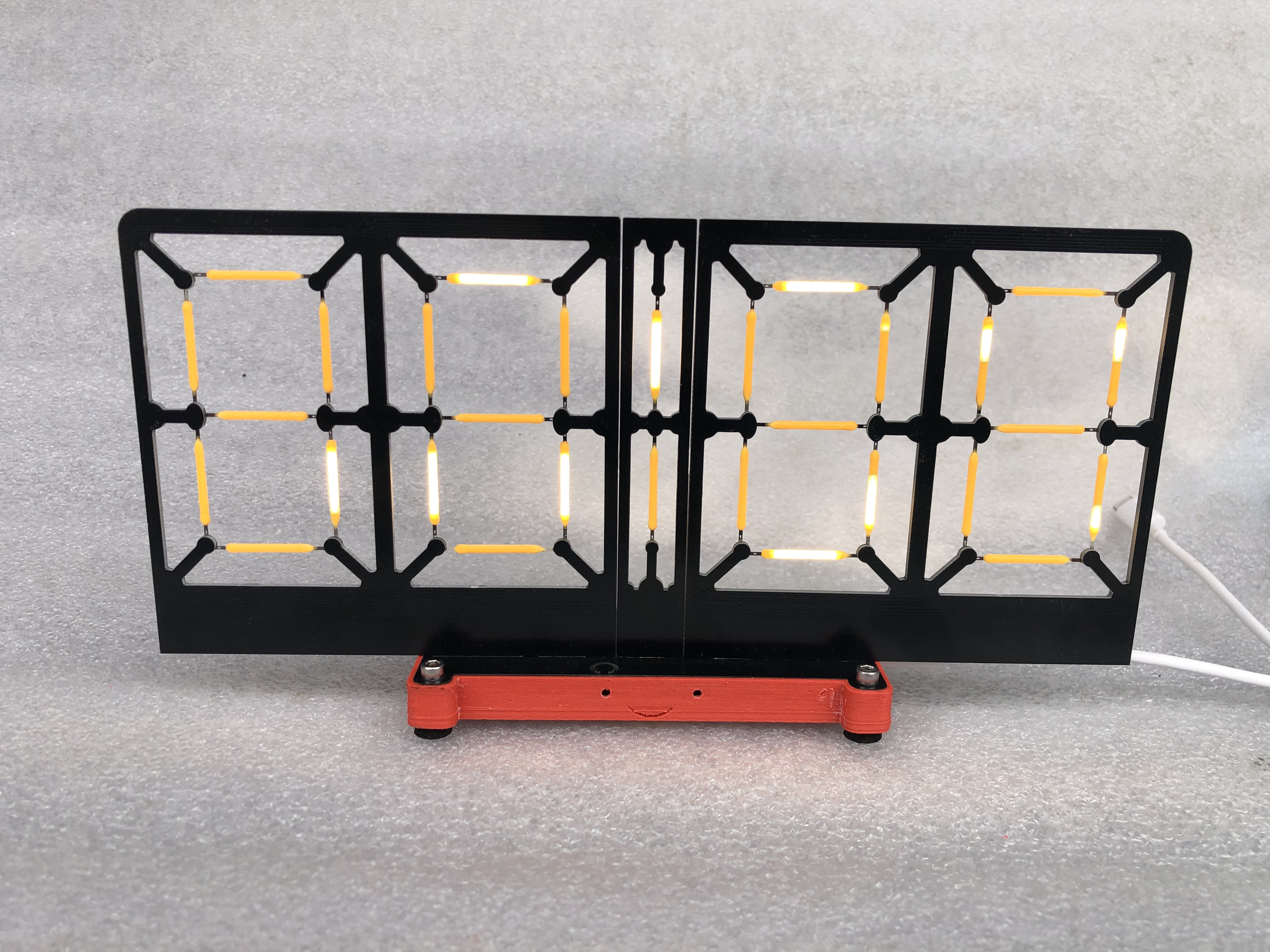
The ESP8266+TM1628 8-digit LED clock features a split design. Those who know, know how it's all about getting a bargain. The display board is 10*10mm, and the driver board is 15*4mm. Both are viable options. The LED board can be either common cathode or common anode.
Xianyu 480P.mp4
8_LED_clock.bin
PDF_ESP8266 Creative 8-Character Clock_pr.zip
Altium_ESP8266 Creative 8-Character Clock_pr.zip
PADS_ESP8266 Creative 8-Character Clock_pr.zip
BOM_ESP8266 Creative 8-Character Clock_pr.xlsx
96881
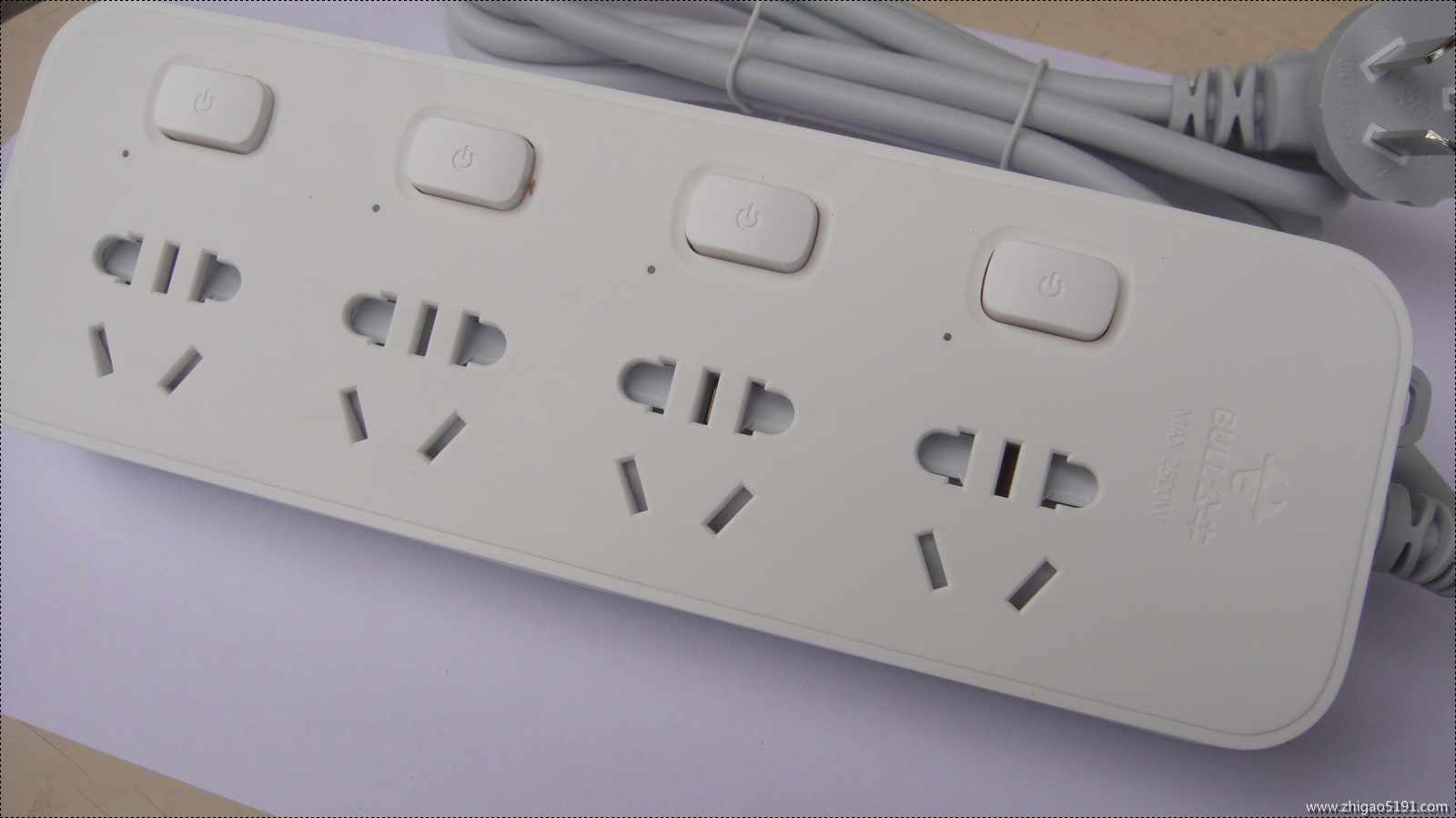
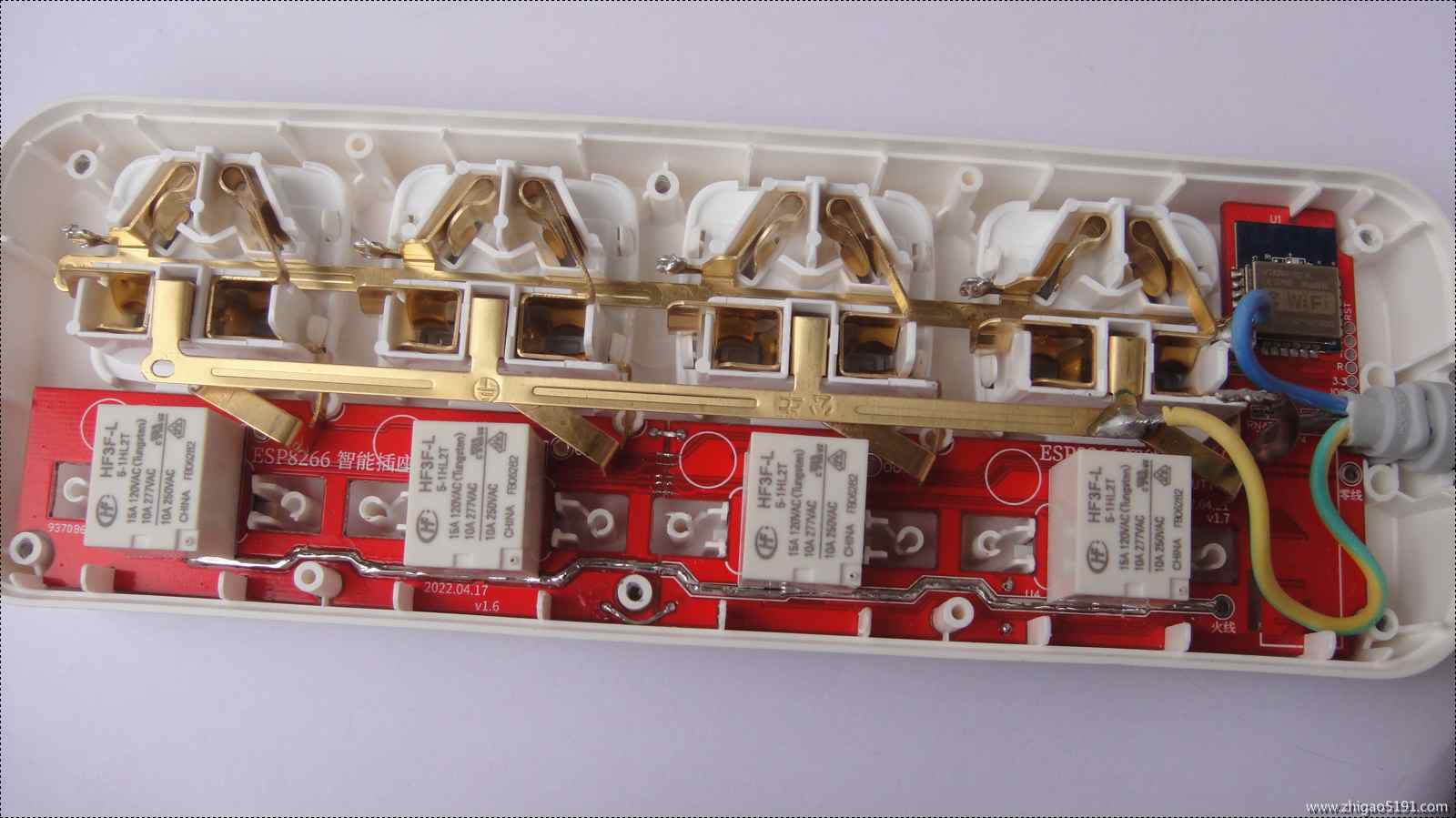
ESP8266 Low Power 4-Position Socket_pr
A socket for controlling a 4-position magnetic latching relay using an ESP8266.
With too many devices like printers, the standby power consumption is high, and they are not compatible with various electrical systems, making them inconvenient to use. Previously, I used a K-series smart socket to connect to a power strip and set timers for all devices. Recently, I started playing with the ESP8266 and learning Arduino, which inspired me to create my own DIY smart socket project.
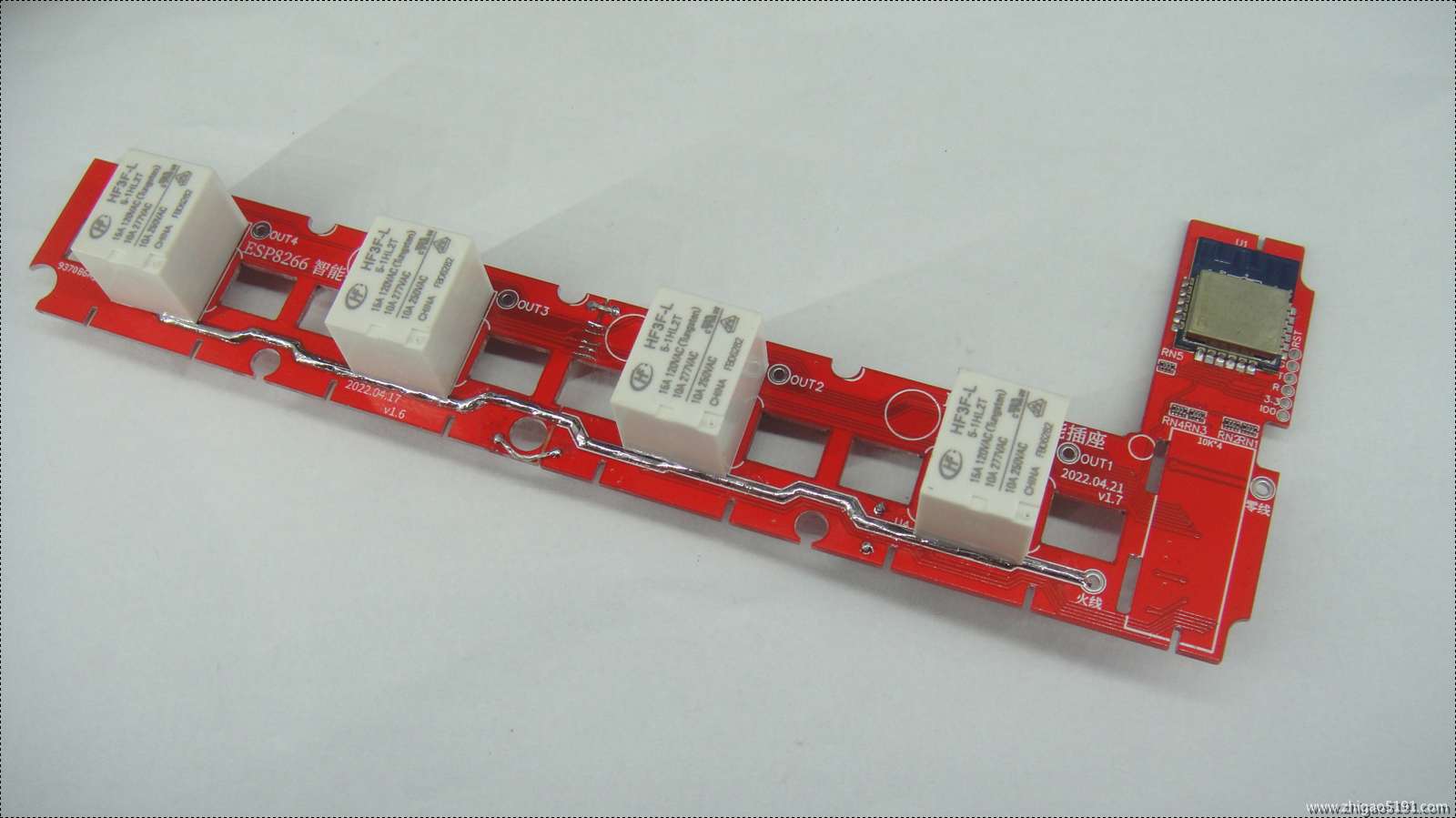
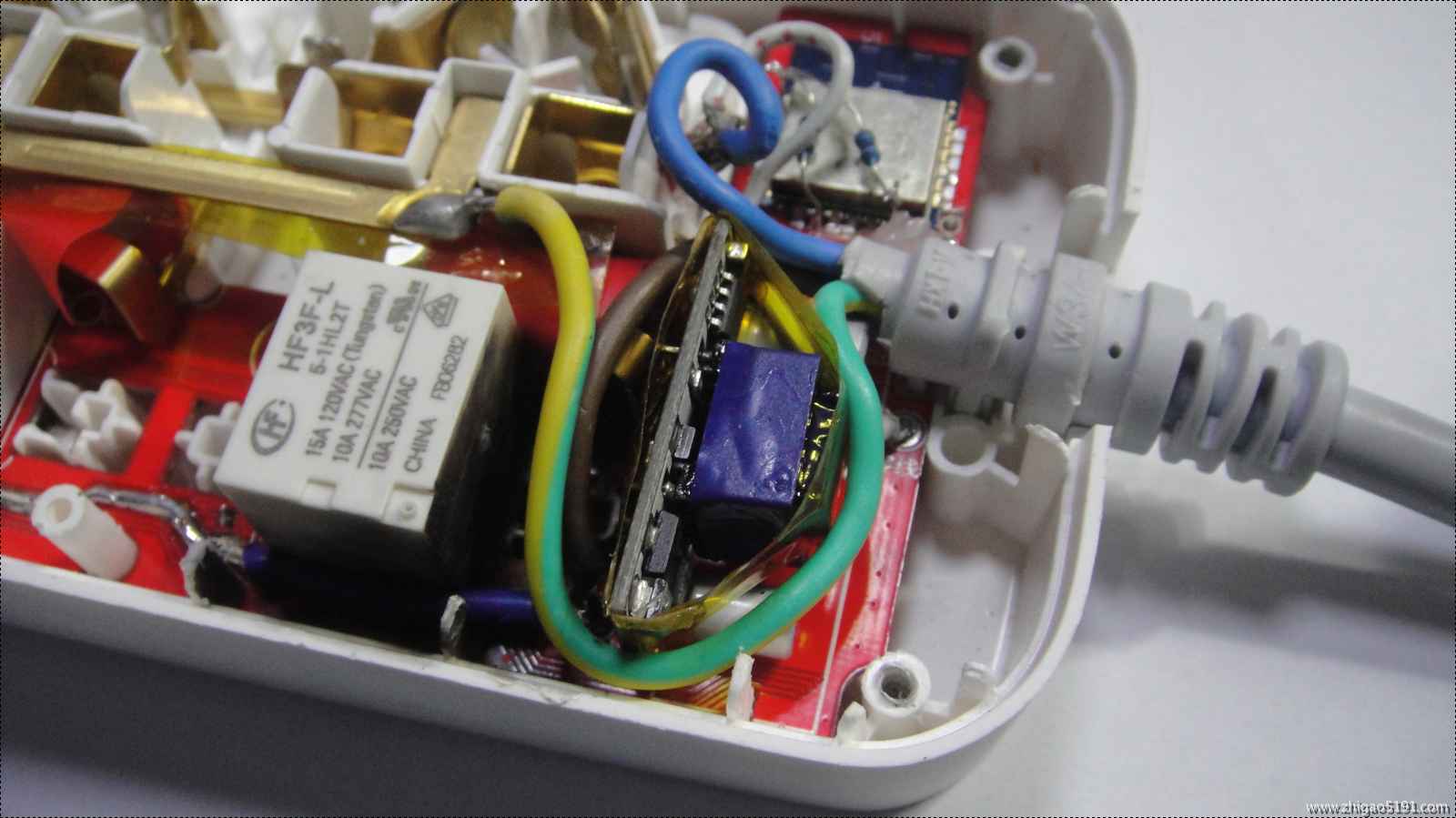
Currently implemented features include: 1. Low power consumption design: using four magnetically latched relays, the relay coils are energized only when switching on/off; otherwise, only the ESP8266 consumes power in standby mode. A USB ammeter test showed a total standby current of 0.08A for the entire PCB and 0.15A for a single relay operation.
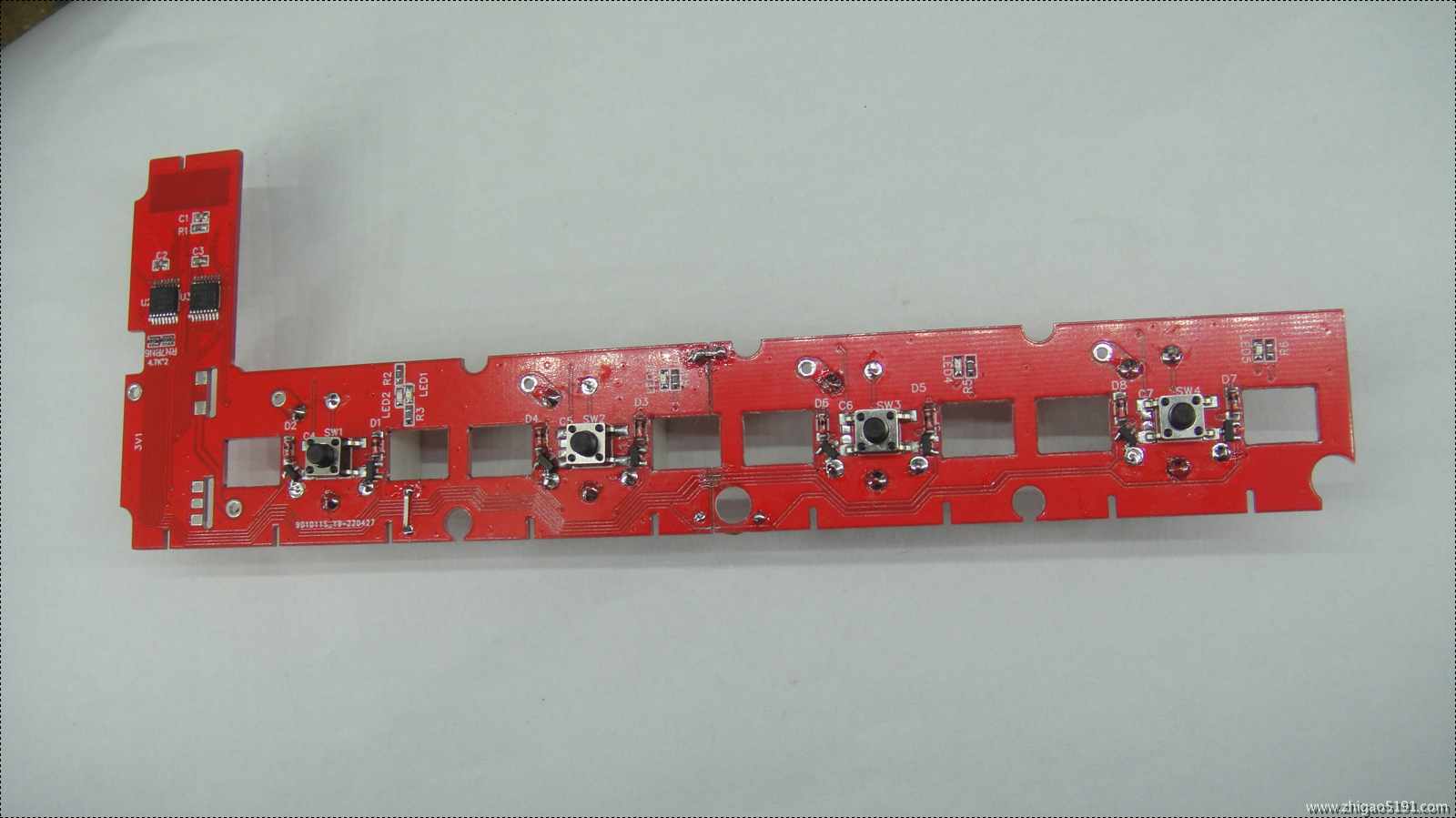
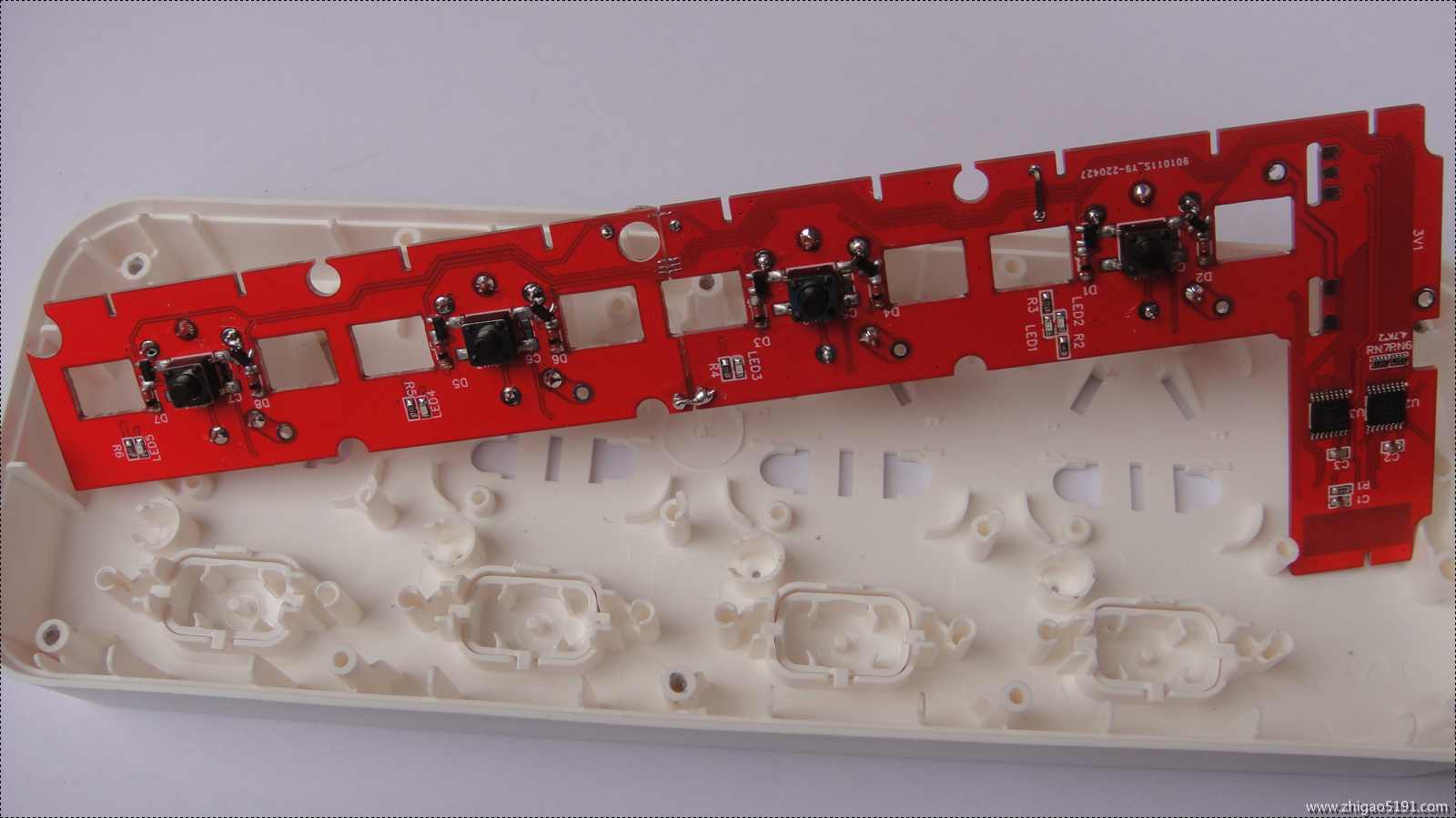
2. In offline mode, the four sockets can be independently controlled by buttons, with corresponding LEDs indicating on/off status.
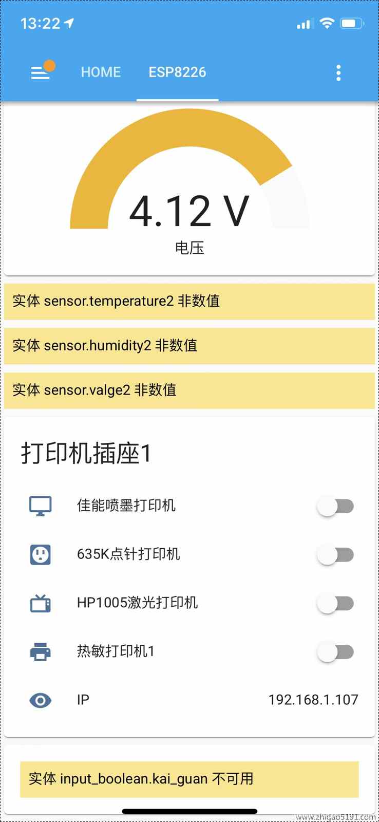
3. Utilizes MQTT protocol to connect to Home Assistant, allowing control of each switch via the Home Assistant web interface or mobile client. The socket will also provide feedback on the status of the button switches. Pressing any button sends the socket's LAN IP address to the MQTT subscription topic.
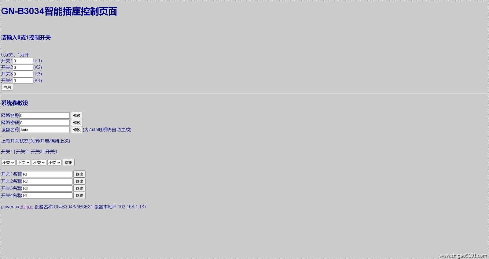
4. Utilizes the ESP8266 webserver service, enabling web-based switch operation (also supports POST parameter control, allowing integration with other automatic control devices or programs).
5. Uses the ESP8266 EEPROM to store switch states. After restarting and powering on, the status of each switch can be individually set to off/on/retain the last state (via web configuration).
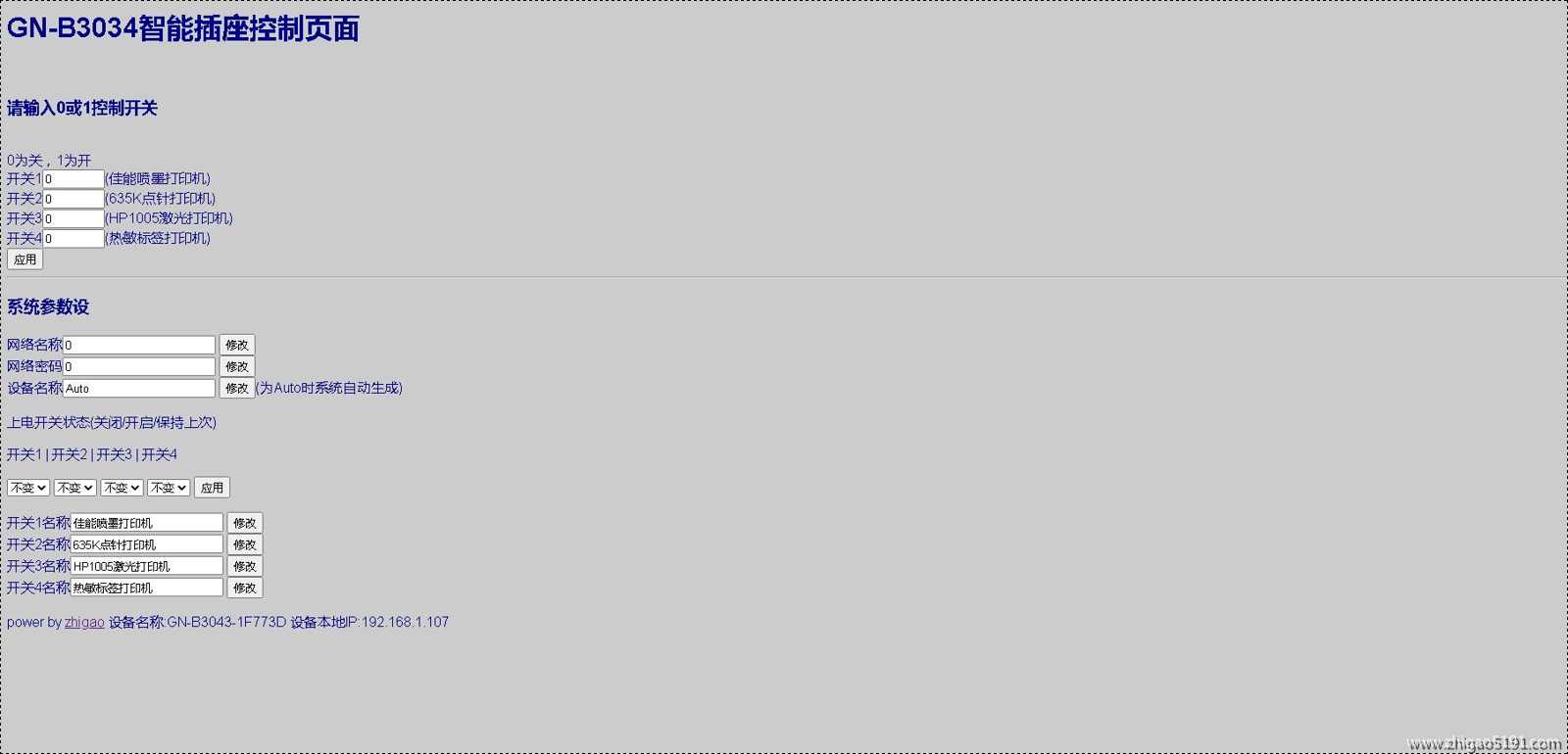
6. The web interface allows setting 4 switch names.
7. Pressing and holding the third button (button 1 on the power cord end) resets the EEPROM parameters.
8. WIFI account and password configuration: While the WiFiManager Chinese library was used for web configuration, occasional program crashes occurred, so it was changed to web page configuration. Please complete the code yourself if needed.
9. Web configuration and built-in timer switch functions are under development; please stay tuned.
Note: The socket has 220V AC power; non-professionals should not disassemble or modify it! This article is for demonstration purposes only. Please be aware of safety precautions if you attempt to replicate it!
This open-source project follows the GPL 3.0 open-source license. However, if you intend to use it commercially, please donate 20% of the net profit to a charity and make the entire donation order public. If you cannot do this, please do not use it commercially.
The
Home Assistant web interface supports socket status feedback

. For firmware upgrades, directly upload the bin file via the web to upgrade

the Home Assistant configuration file
. Add "switch: !include switches.yaml" to the configuration.yaml file.
The switches.yaml file is as follows: This is for one socket. For multiple sockets, change the device name and subscription topic
: platform: mqtt
name: "GN-B3043-1F773D-K1" # Device name, set manually
state_topic: "GN-B3043-1F773D/state/K1" # "GN-B3043-1F773D" MQTT subscription topic, i.e., the socket's device name, can be set manually via the webpage. Setting it to Auto will automatically generate
the command_topic using the MAC address. "GN-B3043-1F773D/set/K1"
unique_id: "32b33778a2614be0a3290f81afdeaba9" #Entity ID, any, just unique. If not set, Home Assistant will prompt that there is no unique entity ID. payload_on: "1"
payload_off: "0"
state_on: "1"
state_off: "0"
optimistic: false
qos: 0
retain: false
icon: mdi:monitor
- platform: mqtt
name: "GN-B3043-1F773D-K2"
state_topic: "GN-B3043-1F773D/state/K2"
command_topic: "GN-B3043-1F773D/set/K2"
unique_id: "32b33778a2614be0a3290f81afdeabaa"
payload_on: "1"
payload_off: "0"
state_on: "1"
state_off: "0"
optimistic: false
qos: 0
retain: false
- platform: mqtt
name: "GN-B3043-1F773D-K3"
state_topic: "GN-B3043-1F773D/state/K3"
command_topic: "GN-B3043-1F773D/set/K3"
unique_id: "32b33778a2614be0a3290f81afdeabab"
payload_on: "1"
payload_off: "0"
state_on: "1"
state_off: "0"
optimistic: false
qos: 0
retain: false
icon: mdi:television-classic
- platform:mqtt
name: "GN-B3043-1F773D-K4"
state_topic: "GN-B3043-1F773D/state/K4"
command_topic: "GN-B3043-1F773D/set/K4"
unique_id: "32b33778a2614be0a3290f81afdeabac"
payload_on: "1"
payload_off: "0"
state_on: "1"
state_off: "0"
optimistic: false
qos: 0
retain: false
Program source code EPS8266_4chazuo__595_V1.8_WEB_202205012_OTA__.rar
#include
#include
#include
#include
#include
#include
#include
Ticker
flipper;//Define timer
//#define PIN_POWER 4 //Indicator light located at GPIO4
#define PIN_LED 13 //Indicator light located at GPIO2
#define KEY1 0 //KEY corresponds to GPI14
#define KEY2 2 //KEY corresponds to GPI14
#define KEY3 4 //KEY corresponds to GPI14
#define KEY4 5 //KEY corresponds to GPI14
int dspin = 16; // Pin 14 of 74HC595, data input pin SI.
int clkpin = 12; // Pin 11 of 74HC595, clock line SCK.
int latpin = 14; // Pin 12 of 74HC595, output memory latch line RCK.
String AutoRigName = "";
// Device name (if "Auto", it will be automatically generated using MAC).
String RIG_IDENTIFIER; // EEPROM address 120.
String K1_name = "Switch 1"; // Switch 1 name, EEPROM address 200.
String K2_name = "Switch 2"; // Switch 2 name, EEPROM address 220.
String K3_name = "Switch 3"; // Switch 3 name, EEPROM address 240.
String K4_name = "Switch 4"; // Switch 4 name, EEPROM address 260.
const char ssid[] = "*****"; // WiFi name, EEPROM. Address 140
const char pass[] = "****"; //WiFi password EEPROM Address 160
ADC_MODE(ADC_VCC);//Set ADC mode to read system voltage
int wifi_flg = 0;//WiFi status flags 0 Not connected 1 Connecting 2 Network configuration 3 WiFi connected 4 MQTT connected
int power_time = 0;//Countdown to power off
int K1_flg;//Define switch 1 status flag EEPROM Address 101
int K2_flg;//Define switch 1 status flag EEPROM Address 102
int K3_flg;//Define switch 1 status flag EEPROM Address 103
int K4_flg;//Define switch 1 status flag EEPROM Address 104
int O595_1_flg = 255;//Define 595 1 flag
int O595_2_flg = 255;//Define 595 1 flag
int K1_ACflag = 2; // EEPROM address 181
int K2_ACflag = 2; // EEPROM address 182
int K3_ACflag = 2; // EEPROM address 183
int K4_ACflag = 2; // EEPROM address 184
uint32_t t=0;//Key timing
WiFiClient espClient;
PubSubClient client(espClient);
const char* mqtt_server = "*******.f3322.org";//mqtt service address
const char* clientID ="8266-001"; // Device ID
//WiFiUDP Udp;//Instantiate WiFiUDP object
//unsigned int localUdpPort = 4321; // Custom local listening port
//unsigned int remoteUdpPort = 8629; // Custom remote listening port
//char incomingPacket[255]; // Save the message sent by the UDP tool
//char replyPacket[] = "Hi, this is esp8266
"; // The message sent only supports English
void callback(char *topic, byte* payload, unsigned int length); // Callback function declaration, used to pass the MQTT client constructor as a parameter
//void write_String(int a,String str); // Write string to EEPROM
// Parameters: MQTT server address, port number, callback function name, connection (WIFI)
PubSubClient mqttClient(mqtt_server, 1833, callback,espClient);
ESP8266WebServer server(80);
ESP8266HTTPUpdateServer httpUpdater;
// Variable constant definition:
String postForms()
{
String htmlCode = "
";
htmlCode += "
";
htmlCode += "
";
htmlCode += "
";
htmlCode += "
";
htmlCode += "
";
htmlCode += "
"; htmlCode += " ";
htmlCode += "
";
htmlCode += "
GN-B3034 Smart Socket Control Page
";
htmlCode += "
Please enter 0 or 1 to control the switch
";
htmlCode += "
htmlCode += " 0 is off, 1 is on
";
htmlCode += "Switch 1
htmlCode += K1_flg;
htmlCode += "" size="5" initial-scale = 2.0 autocomplete="off">(";
htmlCode += K1_name;
htmlCode += ")
";
htmlCode += "Switch 2
htmlCode += K2_flg;
htmlCode += "" size="5" initial-scale = 2.0 autocomplete="off">(";
htmlCode += K2_name;
htmlCode += ")
";
htmlCode += "switch 3
htmlCode += K3_flg;
htmlCode += "" size="5" initial-scale = 2.0 autocomplete="off">(";
htmlCode += K3_name;
htmlCode += ")
";
htmlCode += "switch 4
htmlCode += K4_flg
; += "" size="5" initial-scale = 2.0 autocomplete="off">(";
htmlCode += K4_name;
htmlCode += ")
";
htmlCode += "
";
htmlCode += "
System parameter settings
";
htmlCode += "
htmlCode += "Network name
" ;
htmlCode += " " ; htmlCode += " "; htmlCode += "Network Password "; htmlCode += " "; htmlCode += " htmlCode += "Device Name htmlCode += read_String(120); htmlCode += "" size="20" initial-scale = 2.0 autocomplete="off"> "; htmlCode += "(Automatically generated by the system when set to Auto) "; htmlCode += " Power-on switch status (Off/On/Remain last) "; htmlCode += " Switch 1 | Switch 2 | Switch 3 | Switch 4 "; htmlCode += " htmlCode += " "; htmlCode += " "; htmlCode += "
PDF_ESP8266 Low Power 4-Position Socket_pr.zip
Altium_ESP8266 Low Power 4-Socket_pr.zip
PADS_ESP8266 Low Power 4-Position Socket_pr.zip
96882
Remote button
A machine for turning on and off
Remote Switch Project Overview: This is an innovative project that uses an ESP32 microcontroller connected to the Buffalo Cloud to remotely control physical buttons. It primarily addresses the occasional need to remotely access or manipulate data on my home computer, enabling me to turn it on and off. It also allows me to use the ESP32's Bluetooth keyboard function to input a power-on password.
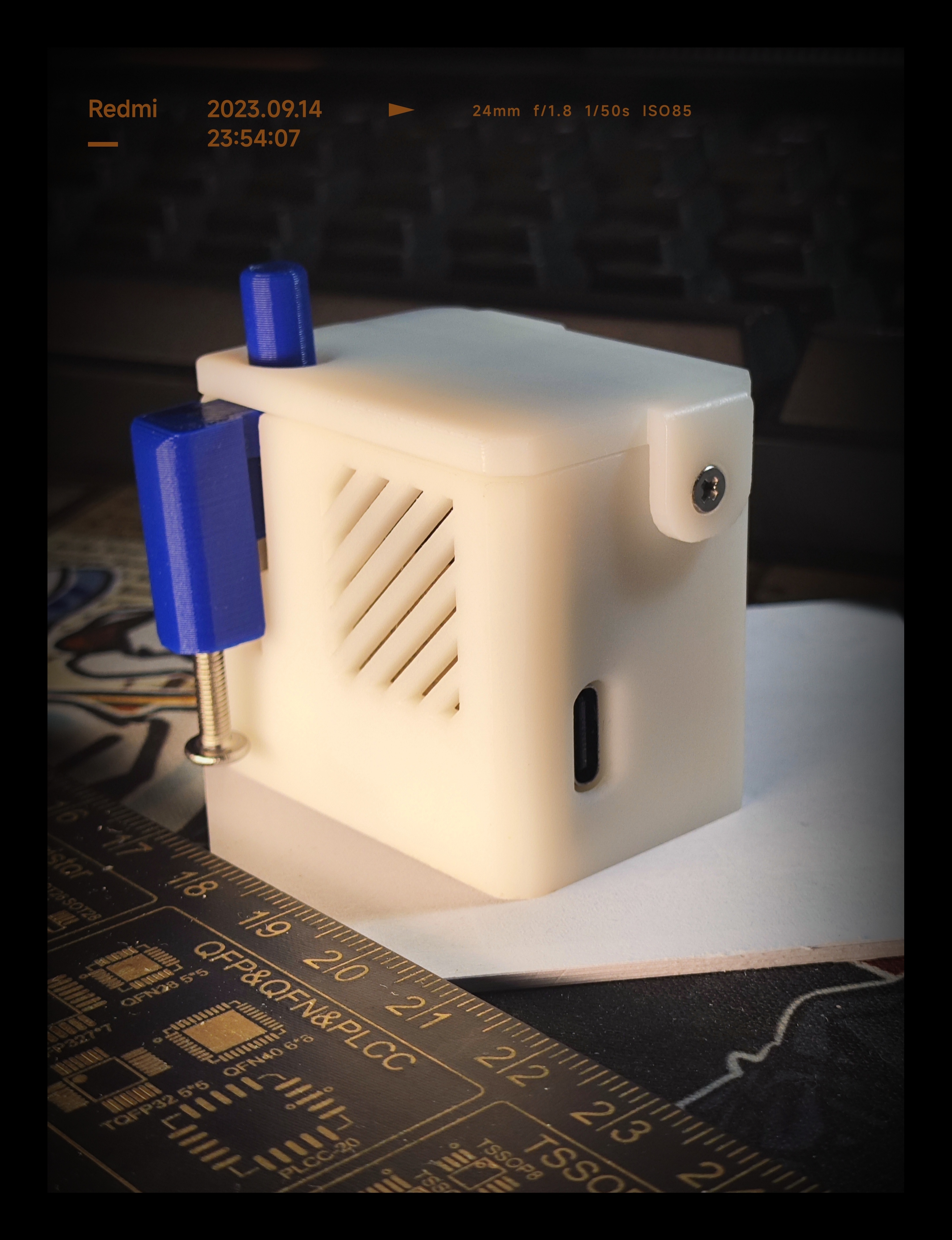
Product Images:
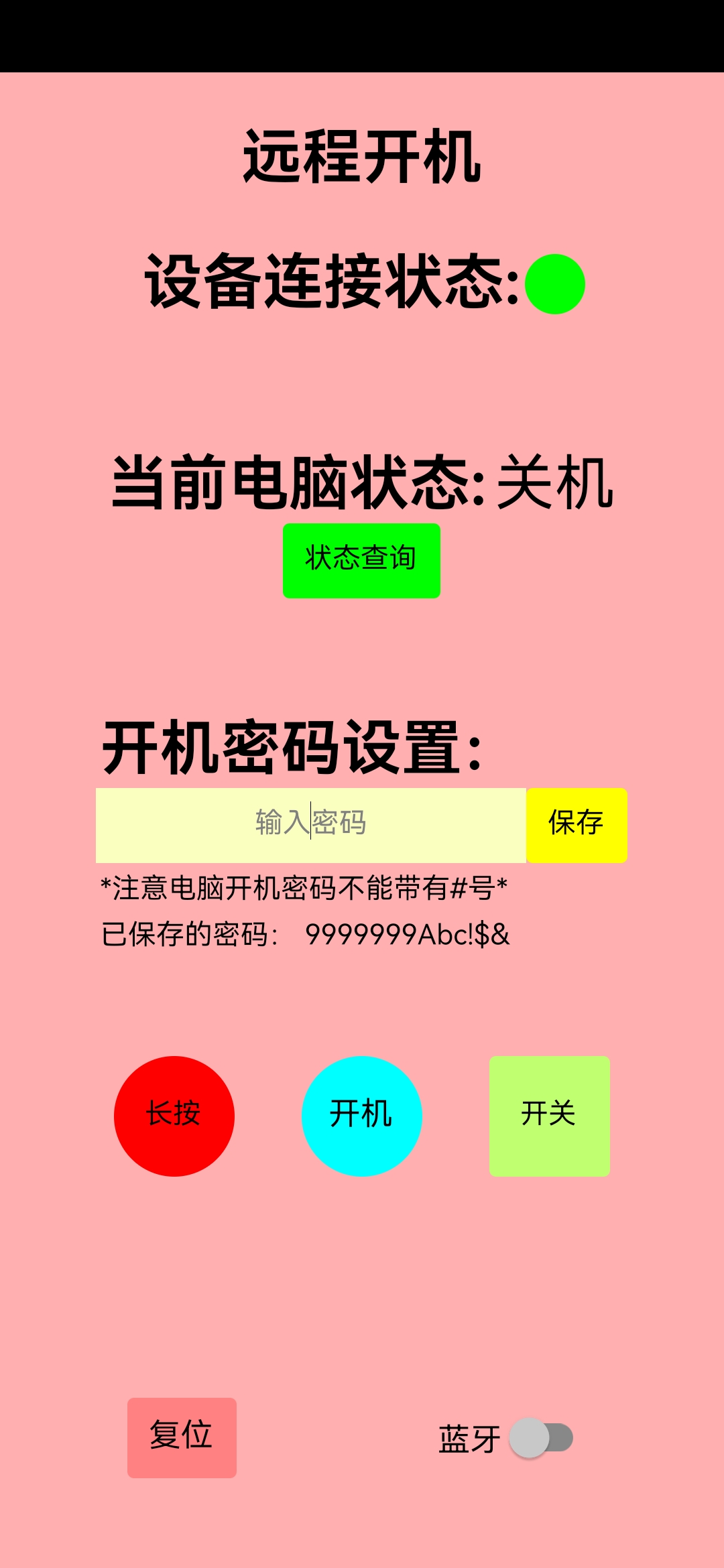
APP:
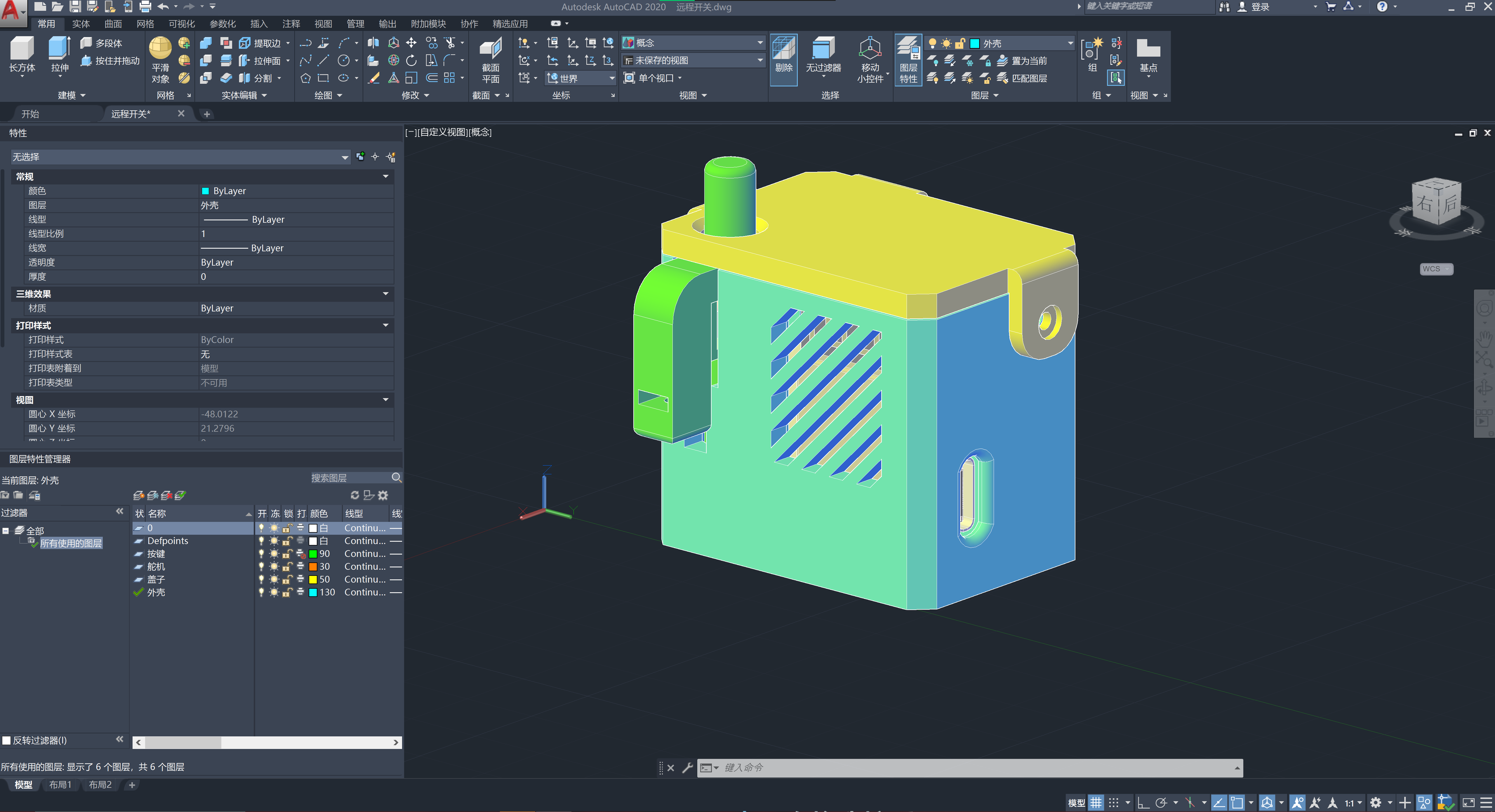
Shell Model:
Operation Steps: Powering on the Computer: 1. Use the APP to click the power button. 2. Wait for the device to power on and automatically enter the password. 3. Connect using remote connection software such as ParseCard or Sunflower. Extended Functions: Enables switching on/off physical buttons such as lights and sockets. Enables switching on/off touch-sensitive buttons.
Advantages: High expandability: 1. Can simulate Bluetooth keyboard and mouse operation. 2. Complete operation process: WeChat mini-program AP network configuration, automatic reconnection after power failure, storage of WiFi and computer passwords after power failure, watchdog mechanism to prevent crashes. Disadvantages: 1. Insufficient servo motor power (this can be solved by replacing with a larger servo motor).
ffd140b9a5ad2d165daae5b770d1bf05.mp4
PDF_Remote Keys.zip
Altium_RemoteKeys.zip
PADS_Remote Keys.zip
BOM_Remote Keys.xlsx
96883
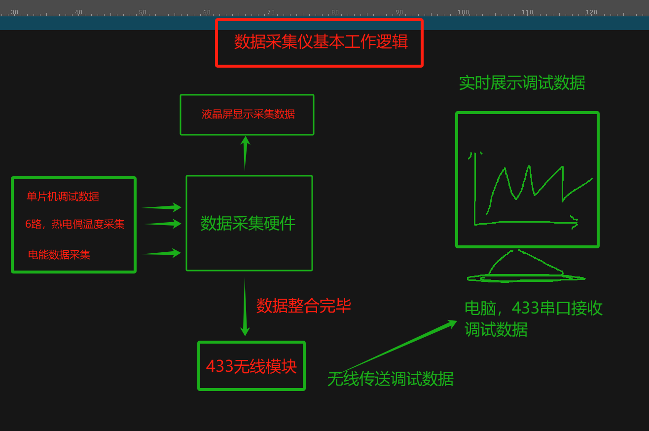
Microcontroller debugger
This system is designed for microcontroller developers of small home appliances, providing data acquisition hardware and real-time curve analysis of program status.
As a small appliance developer, I often find myself using low-end microcontrollers due to cost constraints, which makes testing inconvenient.
This hardware acts as an adapter; developers only need a microcontroller supporting a 125µs timer, a free I/O port, 260 bytes of code, and 24 bytes of RAM.
The compiler indicates the communication driver code size is shown in the image.

Since this project was based on an older board design using Altium Designer, I'm simply copying it to LCSC; prototyping might cost money.
The accompanying host computer software is the work of a former colleague and I cannot share it. Recently, I saw a very powerful curve-setting tool created by a skilled developer.
After testing, this software can correctly decode protocols and record data; I'm now sharing the hardware with everyone. (The schematic diagram is for reference only; the labeling is incorrect. If asked, I simply didn't draw a schematic diagram.)
The basic working logic is shown in the following diagram (sketch):
The basic working logic is shown in the following diagram (actual product image):

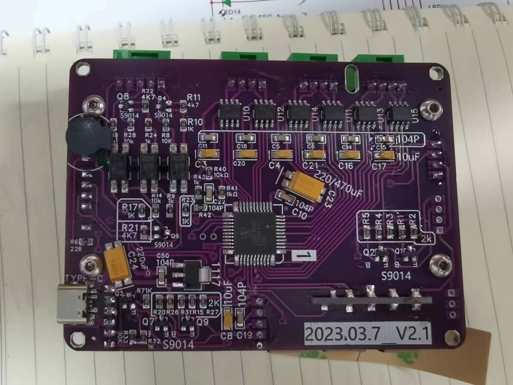
Hardware physical product image :
Touch button board
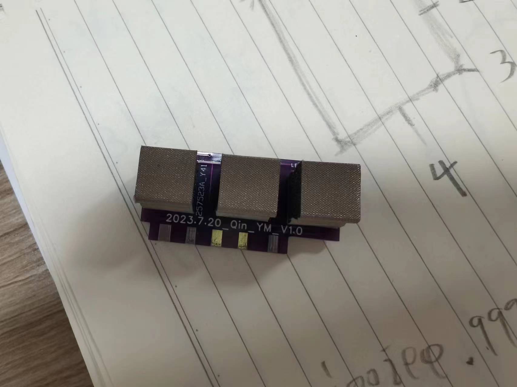
front assembly view;

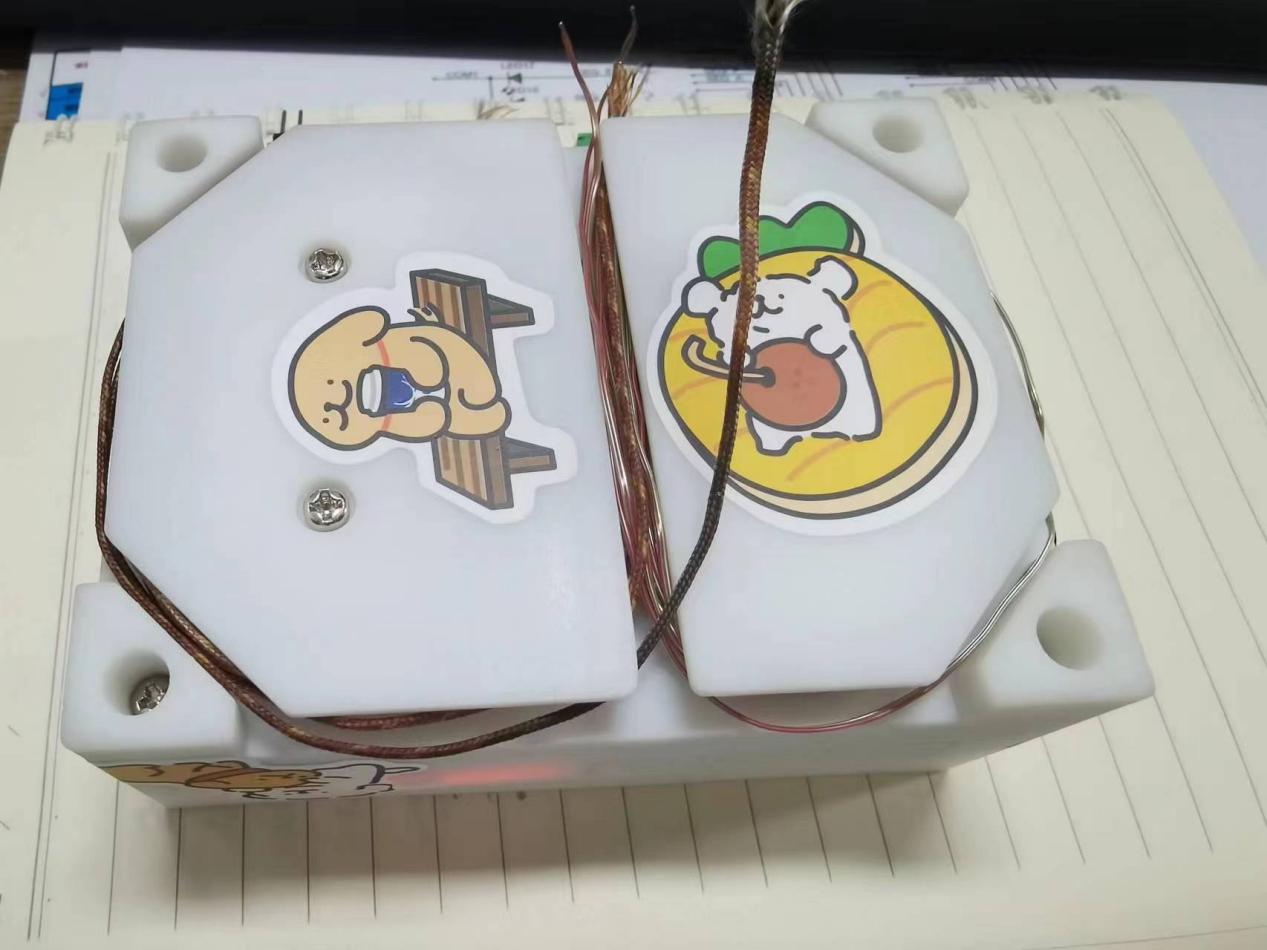
Bottom component
casing with thermocouple wire storage;
Main working parameter interface (microcontroller debugging parameters)
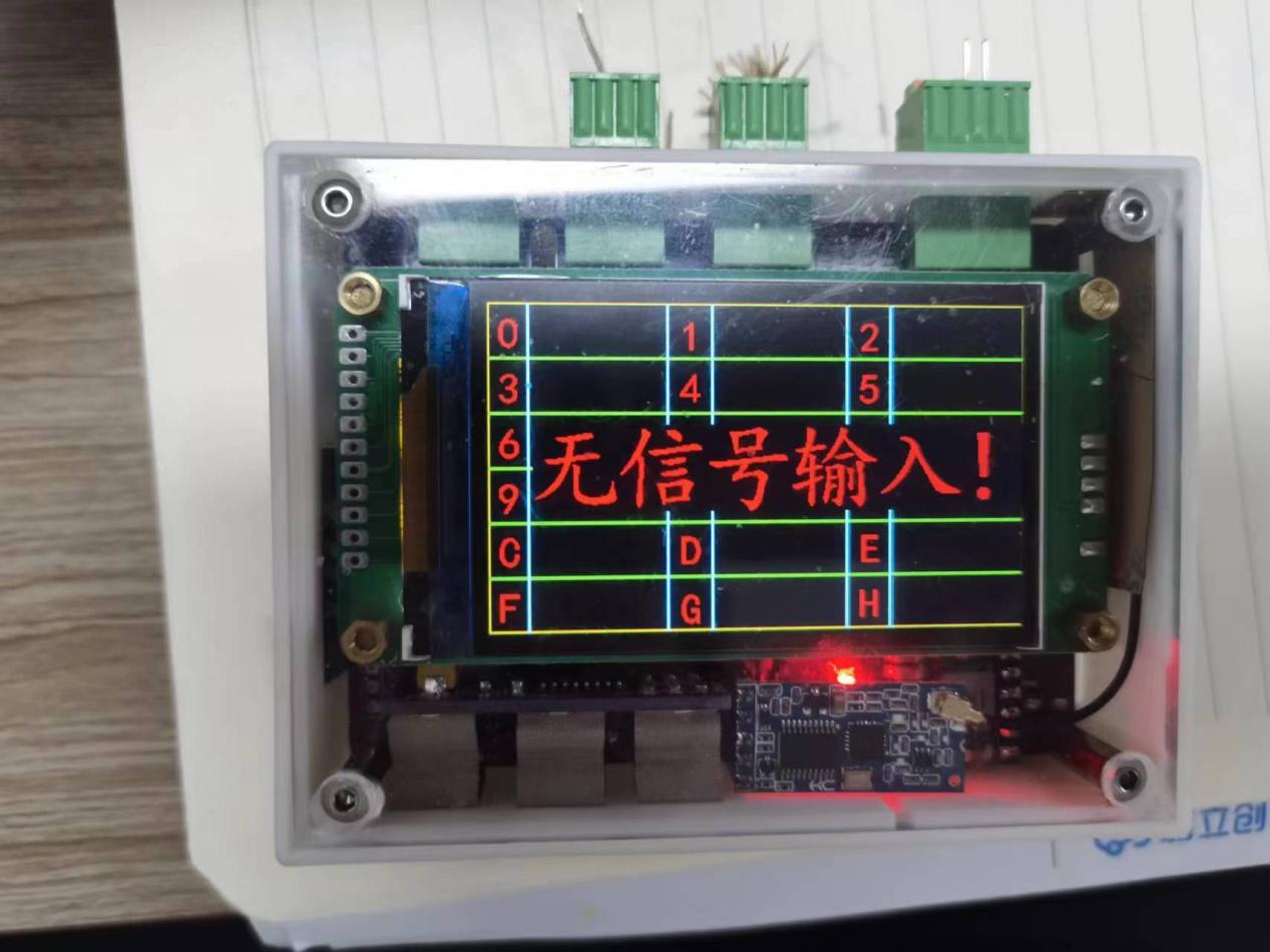
; Power acquisition module, data acquisition interface

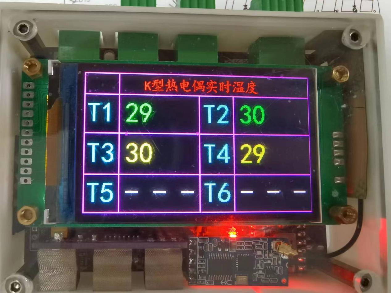
; Thermocouple uses quick-connect terminals;

Temperature acquisition interface;
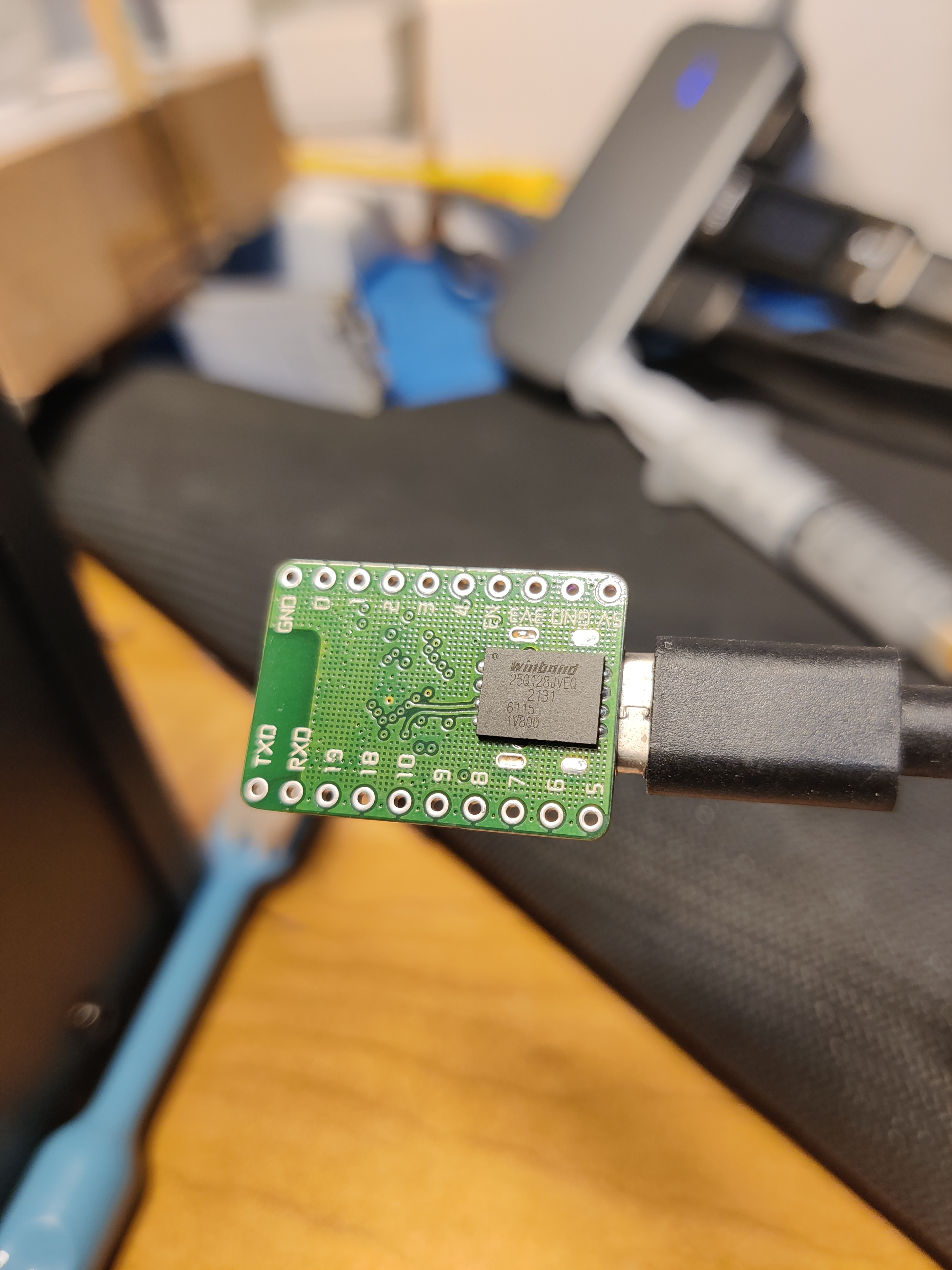
Host computer acquisition interface (The software was found on Bilibili by "麟麟儿呀"; if you don't allow me to use it, kick me and I'll delete it).

Software download address:
http://jooiee.com/cms/ruanjian/115.html
Software video introduction;
https://www.bilibili.com/video/BV1cC4y1N73Q/?spm_id_from=333.1007.top_right_bar_window_history.content.click&vd_source=4a188a523cc2318696816a1288657f42

Saiyuan microcontroller programming tool, LCD screen is programmed via serial port;
https://socmcu.com/cn/tool_show.php?id=18
Communication with host computer, protocol parsing code.txt
IO Simulation Low-Speed Serial Port Driver Code.zip
Main controller programming code SC95F8616.socprj
Touchscreen programming code SC92F8411.socprj
3D Shell.zip
HC-12 Wireless 433MHz Serial Port Module User Manual.zip
Single-chip microcomputer data acquisition board core material list (cost of one set.xls)
Power Module Protocol.jpg
LCD Screen Project.zip
Wiring method.png
PDF_Microcontroller Debugger.zip
Altium_Microcontroller Debugger.zip
PADS_Microcontroller Debugger.zip
BOM_Microcontroller Debugger.xlsx
96884
RP2040 printer motherboard
Raspberry Pi RP2040 printer motherboard
This design is based on the open-source schematics from Bigtreetech (https://github.com/bigtreetech/SKR-Pico), the 5-axis through-hole board from Bilibili user "猪.碧螺" (https://space.bilibili.com/242007488), and the 6-axis integrated 3D printer control board from user "silar" (https://oshwhub.com/silar/rp2040-3d-printer-jian-ban-6z-sui-shen-wifi-10x10-shuang-ceng-usb-1). I mainly disliked screen printing components, so I drew a roughly similar layout for the RP2040 printer motherboard myself.
PDF_rp2040 printer motherboard.zip
Altium_rp2040 printer motherboard.zip
PADS_rp2040 printer motherboard.zip
BOM_rp2040 printer motherboard.xlsx
96886
Single-channel brushless driver version BLDC
This is a high-power 100W BLDC brushless driver board, iterated and improved multiple times. It's a double-layer board with domestically produced components, and has a small footprint of only 5.5*8.8cm. PCB fabrication is available from JLCPCB free of charge. It does not include a main control MCU; signal lines are directly led out. Suitable for RC off-road vehicles and intelligent vehicles.
This is a high-power 100W BLDC brushless driver board, iterated and improved multiple times. It's a double-layer board with domestically produced components, small in size (only 5.5*8.8cm), and the PCB can be custom-made free of charge by JLCPCB.
Features:
It does not include a main control MCU and cannot be directly used to drive brushless motors; it requires a motherboard.
It does not include Hall effect circuits, phase detection circuits, or current detection circuits; input signal lines are directly led out.
It can be used in off-road vehicles and intelligent vehicles. The half-bridge drive design and protection circuit are worth referencing.
Power supply:
I used a 3S battery, and it worked fine at 16V. Higher voltages will require testing.
Pay attention to the voltage rating of the capacitors and power supply chips you solder.
Verified in an intelligent vehicle competition; open the project file using the "Open with Editor" button in the upper right corner.
PDF_Single-channel brushless driver version BLDC.zip
Altium_Single-Channel Brushless Driver Version BLDC.zip
PADS_Single-channel brushless driver version BLDC.zip
BOM_Single-channel brushless driver version BLDC.xlsx
96887
electronic


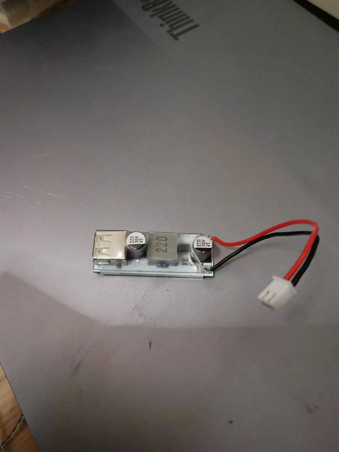 It's recommended to use heat shrink tubing during use to prevent accidental short circuits from contact with other objects.
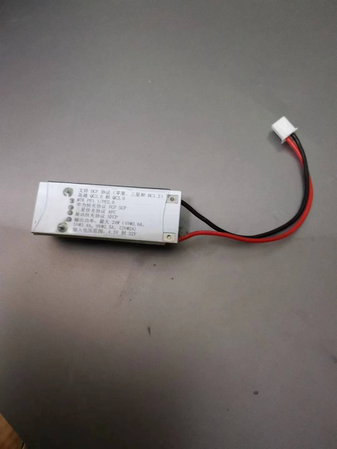


 京公网安备 11010802033920号

 14FMN-SMT-TF


