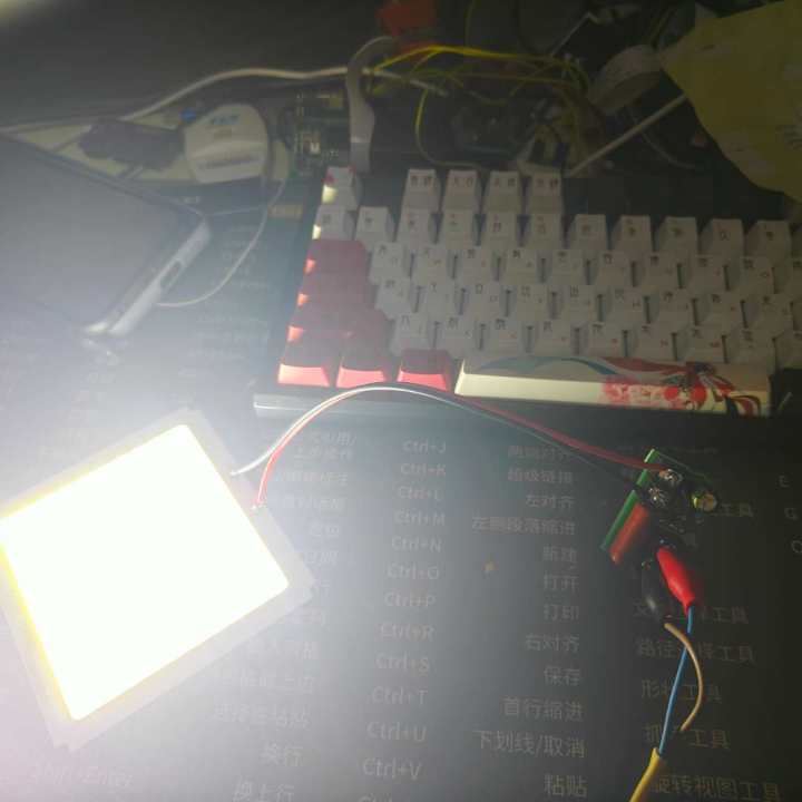
Caution: Exercise caution when using the board. Do not touch it after powering on or off. I added a bleed resistor to the CBB, but I forgot to add a bleed resistor to the output electrolytic capacitor, which may pose a risk of electric shock. Therefore, do not touch it after powering on unless you are sure the output voltage is low. Also, ensure the board is insulated!
Note: Do not use the wrong polarity; it is marked on the PCB!
Caution: Exercise caution when using the board!
The circuit is simple and can be used with LED boards from a few volts to over 100 volts, but it is more recommended for higher voltage LED boards. Driver boards up to 72V are relatively inexpensive. Generally, the output current of RC step-down converters is not large. Bridge rectification typically provides 60-70mA current with a 1uF CBB capacitor. The
output current value is determined by the capacitance value of the CBB; the larger the capacitance, the higher the output current. There are many detailed introductions on Baidu.
I recommend using 450V rated CBB and aluminum electrolytic capacitors for safety. Because I bought too many of these through-hole connectors early on, I had to prioritize using up my existing inventory.
PDF_COB-LED-Driver Board@220VAC.zip
Altium_COB-LED-Driver Board@220VAC.zip
PADS_COB-LED-Driver Board@220VAC.zip
BOM_COB-LED-Driver Board@220VAC.xlsx
96967
[Smart Hardware] Offline Voice Bluetooth Speaker
This is an offline Bluetooth speaker designed based on the Qiying Tailun offline voice chip, which can still recognize voice even without a network connection!
Who could resist a Bluetooth speaker that can perform voice recognition without relying on the internet? The motivation for this project stemmed from my unreliable home Wi-Fi, which had left my Tmall Genie gathering dust. I happened to learn about the Qiying Tailun CI1302 third-generation voice chip, which boasts an extremely high recognition rate. The voice wake-up phrase and response can be customized, and it even offers an offline voice Bluetooth speaker solution – perfectly meeting my needs! Let's take a look at this solution together; by learning it, you too can design your own Bluetooth speaker!
I. Circuit Analysis
When designing the circuit, it's essential to understand the core chip. Here, we've chosen the Qiying Tailun CI1302 chip, with a maximum CPU frequency of 220MHz and an operating voltage range of 3.6V~5.5V. It features one IIS interface, three UART interfaces, one IIC interface, six PWM interfaces, and ten GPIO ports, allowing for independent control or integration with a microcontroller or other chips. This chip supports 300 offline command words and also features a command word self-learning function, allowing for easy modification of wake-up words and response phrases – a very convenient feature.
Qiying Tailun's official website happens to have an evaluation board with Bluetooth functionality. Downloading the evaluation board documentation from the website and referencing its schematic, I designed the following circuit:

In the PCB design, ensure C10, C11, C12, and C15 are placed close to the chip. Serial port 0 is reserved for program download, and serial port 1 is used for Bluetooth communication. Digital and analog grounds are separated and connected using resistor R5 for a common ground. The power supply is a convenient everyday Type-C power supply, outputting 3.6V through an HT7336 step-down chip to power the Bluetooth chip. The microphone input is filtered by two 100nF capacitors.
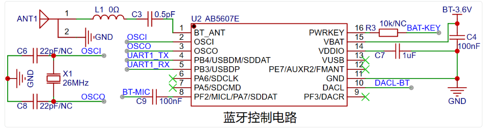
The Bluetooth chip used is the AB5607E chip from Zhongke Lanxun. The peripheral circuit is simple; a separate antenna circuit can be designed and directly connected to the voice recognition chip. For the 26MHz crystal oscillator, a 20pF ±20pPM oscillator should be selected to avoid malfunction.
For good audio sound, an amplifier is essential. When designing, you can choose between a mono or stereo amplifier based on your needs. Here, we chose a commonly used and inexpensive Class D amplifier chip, the 8002A. R10 is a pull-up resistor. The audio signal passes through an RC filter and enters pin 4 of the chip. R15 is a feedback resistor connected to the output pin VO1, forming an inverting amplifier circuit. The amplification factor can be adjusted by changing the value of R15 to change the output volume. Here, you can adjust the sound amplification factor according to the actual selected speakers. The amplification factor is: -HPOUT*R13/R15+(-DACL-BL*R14/R15).

The speaker chosen here is a 4Ω 3W speaker, which combines high, mid, and low frequencies and has decent sound quality. The key point is that this speaker is very cheap!

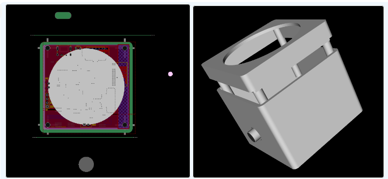
II. Shell Design
After designing the PCB, you can directly design the shell file in JLCPCB EDA Professional Edition. Shell design becomes very simple here. You only need to combine the board frame to set its shell shape and size, make holes in the corresponding positions, and set screw posts for support. The designed model is shown in the image below:
III.
3D Printing Which 3D printing company is the best? Check out JLCPCB's 3D Monkey! 3D Monkey 3D printing not only supports resin and nylon, but also metal, color printing, and the well-known FDM printing. There's always a process that meets your needs. It's worth mentioning that the 3D Monkey platform currently offers monthly coupons. For details, please click the following link:
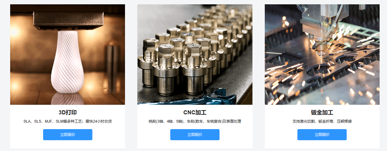
Click to view 3D Monkey free printing.
IV. References
If you want to learn more about offline speech recognition technology, you can directly visit the Qiying Tailun official website to explore. It contains a large number of application solutions and firmware for learning and reference:

https://aiplatform.chipintelli.com/
3D Shell - Offline Voice Bluetooth Speaker.zip
PDF_【Smart Hardware】Offline Voice Bluetooth Speaker.zip
Altium_【Smart Hardware】Offline Voice Bluetooth Speaker.zip
PADS_【Smart Hardware】Offline Voice Bluetooth Speaker.zip
BOM_【Smart Hardware】Offline Voice Bluetooth Speaker.xlsx
96968
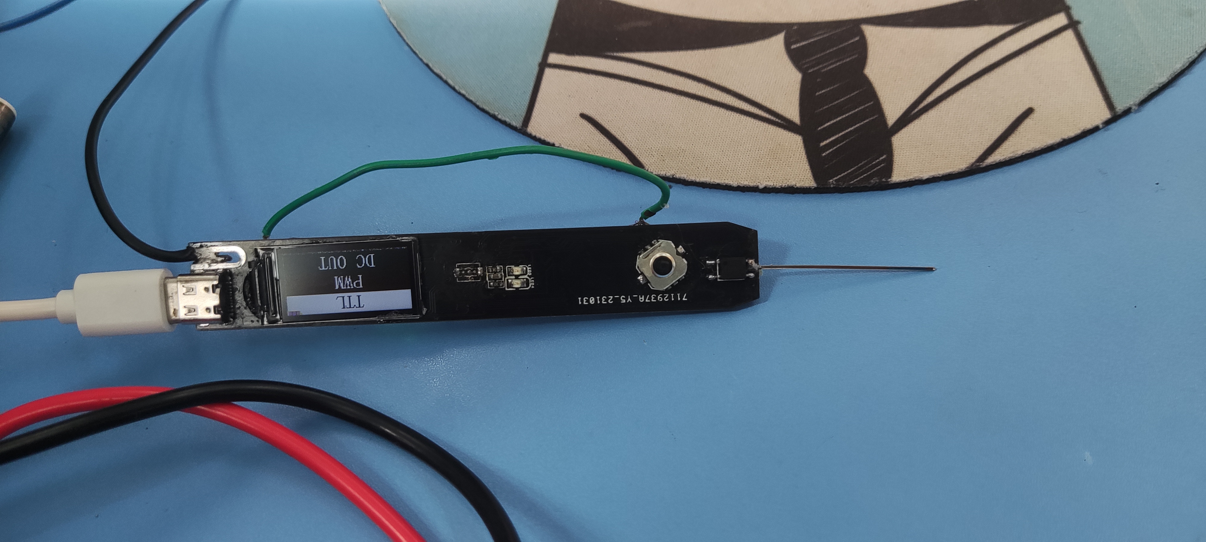
Multifunctional test pen
A portable multi-functional test pen with voltage measurement, continuity measurement, diode detection, and signal output functions was built based on the CW32F030.
I. Existing Functionality
: Continuity measurement, threshold resistance
diode measurement, conduction voltage measurement, and a diode that smokes (true).
PWM output,
PWM input
, DC output, outputting a specified voltage.
II. Remaining Issue:
In the diode continuity measurement function, one diode and MOSFET smoke, while other functions work normally. The reason is unclear; the voltage is normal.
I forgot to provide pads for the battery pins when designing the board, so I had to use other pads.
III. Component Replacement Ideas:
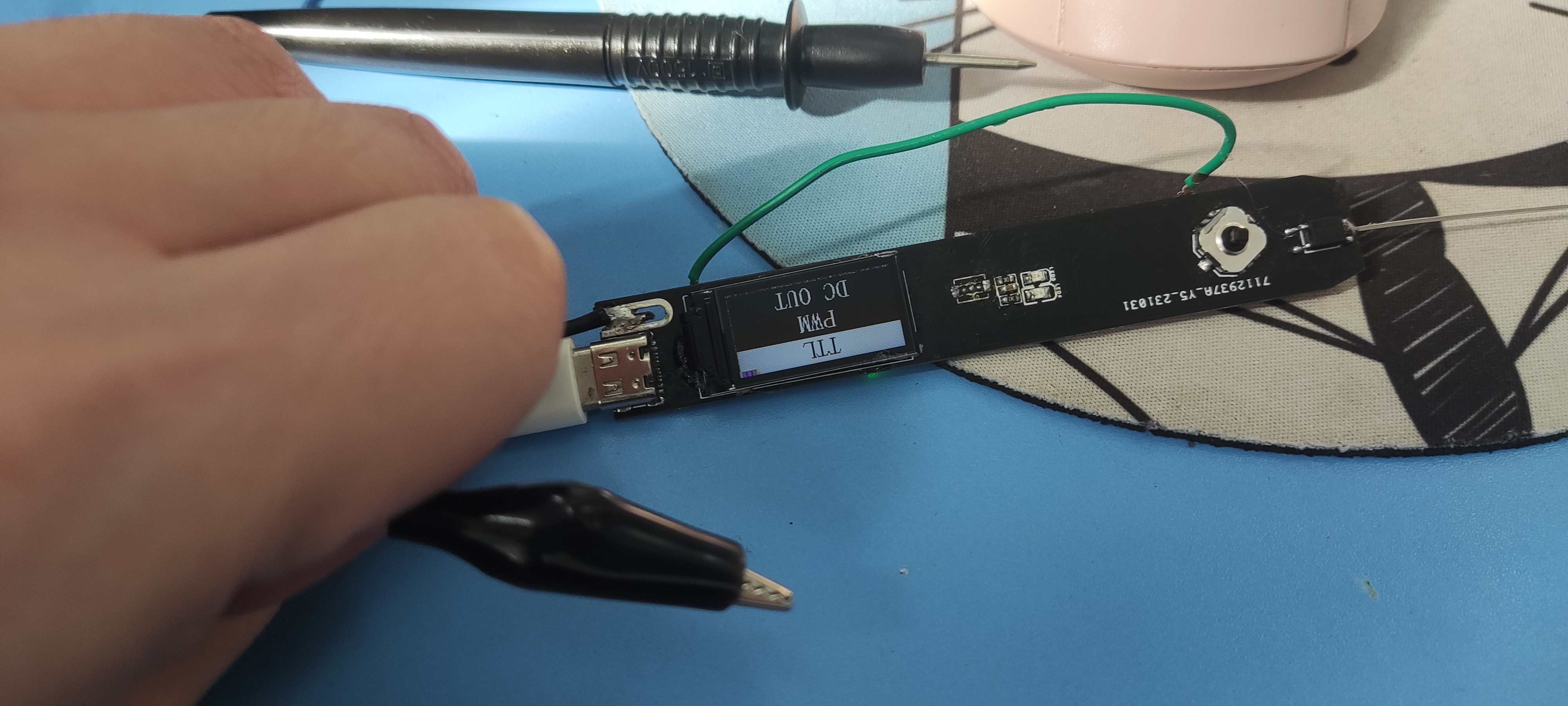
Due to the high price and shipping costs of the probe pins and connector, and a lack of funds, I used long header pins instead (surprisingly, they worked well). I used an alligator clip for the connector, which is very convenient (another DuPont wire could be added).
Illustration:
VID_20231127_121131.mp4
PDF_Multifunctional Test Pen.zip
Altium Multi-functional Test Pen.zip
PADS_Multifunctional Test Pen.zip
BOM_Multifunctional Testing Pen.xlsx
96969
MINI Lithium Battery Protection Board 1S-3S
Lithium battery protection boards, including single-cell protection boards, 2-cell protection boards, and 3-cell protection boards in modular form. Low power consumption
supports the following protection functions:
1. Over-discharge protection;
2. Overcharge protection;
3. Overcurrent protection
; 4. Short circuit protection.
The functions of the 1S and 2S boards have been verified. The 3S chip has been ordered but has not yet arrived, so it cannot be tested at the moment.

PDF_MINI Lithium Battery Protection Board 1S-3S.zip
Altium_MINI Lithium Battery Protection Board 1S-3S.zip
PADS_MINI Lithium Battery Protection Board 1S-3S.zip
BOM_MINI Lithium Battery Protection Board 1S-3S.xlsx
96971
PAM8403 power amplifier
Low-cost Class D amplifier board
The PAM8403 is a compact, low-cost amplifier board that supports 3W dual-channel audio playback.
PDF_PAM8403 power amplifier.zip
Altium_PAM8403 power amplifier.zip
PADS_PAM8403 power amplifier.zip
BOM_PAM8403 power amplifier.xlsx
96972
electronic


 京公网安备 11010802033920号

 HIN238CBZ-T


