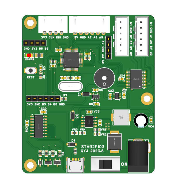
A self-balancing scooter control board based on STM32F103C8T6.
Main Control Chip: The STM32F103 was chosen as the main control chip. The STM32F103 is a microcontroller based on the ARM Cortex-M3 core, featuring abundant peripheral resources and powerful computing capabilities, making it suitable for controlling the movement of the self-balancing scooter.
Driver Chip: The TB6612 was chosen as the driver chip. The TB6612 is a dual-channel DC motor driver chip, capable of providing sufficient current and voltage to drive the scooter's motors. It features overload protection and current detection functions, effectively protecting the motor and circuitry.
Sensors: Self-balancing scooters typically use accelerometers and gyroscopes to sense the tilt angle and attitude of the vehicle for balance control.
Power Supply: Self-balancing scooters require a stable and reliable power supply system. A lithium battery can be selected as the main power source, with a TPS5450 voltage regulator chip for power supply.
Motors: Self-balancing scooters typically require two motors to drive the wheels. A brushless DC motor can be selected as the drive motor, featuring high efficiency, low noise, and long lifespan.
PDF_STM32F103 Self-Balancing Scooter Third Edition PRO.zip
Altium_STM32F103 self-balancing scooter third edition PRO.zip
PADS_STM32F103 Balance Scooter Third Edition PRO.zip
BOM_STM32F103 Self-Balancing Scooter Third Edition PRO.xlsx
97007
Serial communication module based on STM32F103
This module can be used to display serial port data. Currently, it can only display a single line, enable and stop receiving, and reset. The baud rate is 115200 and cannot be modified. The display currently has bugs and will be improved in future updates.
This module can be used to display serial port data. Currently, it can only display one line, enable and stop receiving, and reset. The baud rate is 115200 and cannot be modified. The display has bugs, and it will be improved later, for example, by changing the baud rate. Currently, the OLED driver uses 1306, and it seems that different OLED drivers cannot be used simultaneously. When sending data, a newline character "
" needs to be added at the end for the data to be displayed. For example, an example of sending the character '1' via serial port using STM32 is as follows: `printf("1
");` The project is a HEX file.
Hardware IIC.hex
PDF_Serial Port Interaction Module Based on STM32F103.zip
Altium_serial port interaction module based on STM32F103.zip
PADS_Serial Port Interaction Module Based on STM32F103.zip
BOM_Serial Port Interaction Module Based on STM32F103.xlsx
97008
Power supply module (stable 3.3V)
DC-DC step-down module, input 4.5V-16V, output 3.3V/3A, can power a microcontroller.
This project is a DC-DC step-down module with an input of 4.5-16V and an output of 3.3V, which can directly power a microcontroller.
The test video is available on Bilibili: https://www.bilibili.com/video/BV1z34y1c76R/?spm_id_from=333.999.0.0&vd_source=8feac9e8c73c90f7dd3c70ab08350e52
PDF_Power Module (Stable 3.3V).zip
Altium power module (stable 3.3V).zip
PADS_Power Module (Stable 3.3V).zip
BOM_Power Module (Stable 3.3V).xlsx
97009
CM1033_ETA3000_Three-cell lithium-ion battery series protection balance board
CM1033_ETA3000_Three-cell lithium-ion battery series protection balance board
This is a verification board for a CM1033_ETA3000 three-cell lithium-ion battery series protection balance board. It works normally, but hasn't been thoroughly tested (due to lack of resources).
When using the ETA3000, please note the following:
1. Before installing the batteries, connect them in parallel to balance the voltage. Installing batteries with significantly different voltages will damage the chips.
2. When installing the batteries, connect the EN pin to the BATAN pin with a jumper wire. Do this for each battery. After installing the batteries, remove the jumper wire. Installing batteries while in operation will damage the chips.
3. When removing batteries, also connect the EN and BATAN pins with a jumper wire; otherwise, the chips will damage, especially if BATP and BATAN are connected. Directly removing BATC will definitely cause damage.
4. Do not touch the chips unnecessarily. The image below shows a chip damage caused by a finger probe, which also burned the board.

I hope everyone can successfully build their boards without damaging chips or burning batteries, and that everything works normally.
PDF_CM1033_ETA3000_Three-cell lithium-ion battery series protection balance board.zip
Altium_CM1033_ETA3000 Three-Cell Lithium-ion Battery Series Protection Balance Board.zip
PADS_CM1033_ETA3000_Three-cell lithium-ion battery series protection balance board.zip
BOM_CM1033_ETA3000_Three-cell lithium-ion battery series protection balance board.xlsx
97010
electronic


 京公网安备 11010802033920号

 MI-P6W2-MYW


