My 3D casing and lithium battery are on their way, so they can't be shown here yet.
I. Design Inspiration:
In the JLCIC Instrumentation Training Camp, I chose to replicate He Diangong's multi-functional test pen – the "Dianjing Pen"
. II. Circuit Analysis:
1. Power supply
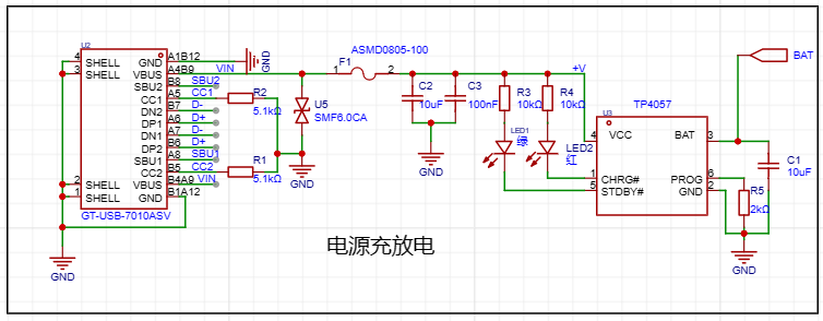
: A 16-pin Type-C interface is used for charging and discharging. The numerous interfaces increase expandability. The Type-C interface here is not used for data transmission. Because this is a test pen, it needs to measure voltage.
If a large voltage is accidentally applied, it may damage the device. To prevent dangerous voltage transmission, it is not used.
A 5.1K resistor is used as a pull-down resistor (CC1, CC2).
The TP4057 is a commonly used battery charging chip. This design is based on a typical case (BAT is my 3.7V lithium battery power supply).
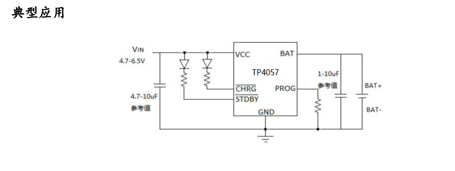
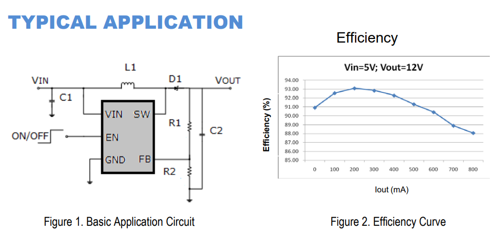
The component's datasheet contains a lot of information about it, including its typical applications.
We will use it frequently in our future learning and application, so we need to learn how to read its datasheet.
2. Power control and voltage regulation

conversion uses a P-channel linear regulator (
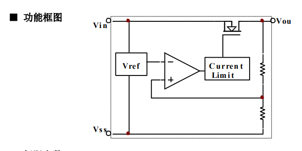
BAT+). As mentioned earlier, it uses a 3.7V lithium battery.
When there is no Type-C power supply, the lithium battery is used for power supply, switching using the P-channel regulator.
3. Output detection:

This is the power acquisition section. Because the value is large when measured directly, voltage division is performed before acquisition.
4. Button control:

The button control section uses a five-way joystick switch (4-way + center button), which is a button with five switches.
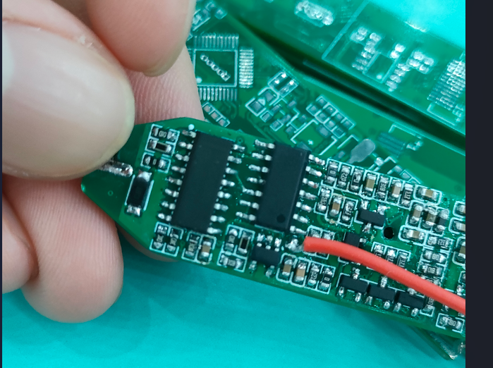
5. Main control chip configuration: The main
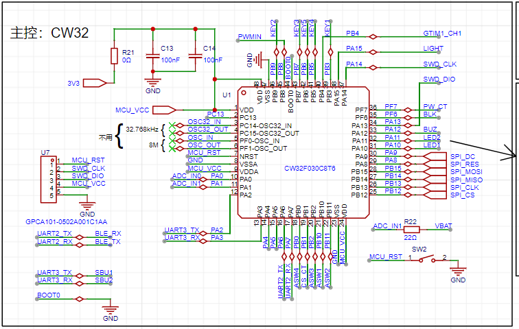
control chip is a CW32F030C8T6, connected to a small header for program download. This header only uses one pad and does not need to be connected to a pin header. A
high-precision clock and low-speed crystal oscillator are not needed for timing, so this part of the circuit is omitted. The unused interfaces of this circuit are marked.
I have drawn the circuit diagram for this part in another schematic diagram of this project.
The reset button here is connected to the header port, so the button will be soldered after the program is burned.
The labeling method I learned is from an electrician named He. (It allows you to quickly find the pins and understand their functions.)
6. Human-Computer Interaction:
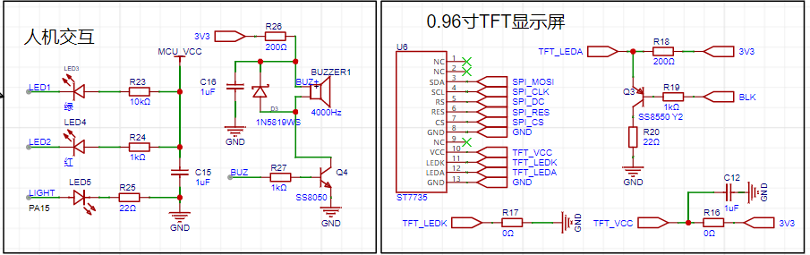
The current-limiting resistor in this circuit can be changed according to your needs
. Two LEDs (choose two different colors) are used to display the high and low levels of the measurement.
An additional LED is used for illumination, placed at the front of the PCB board for easy detection in low-light conditions.
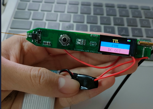
The display screen is a 0.96-inch TFT color screen used to display the measured values.
A buzzer was also used for indication. The schematic diagram uses an electromagnetic buzzer, but I used a voltage-type buzzer during soldering to reduce power consumption.
7. Bluetooth
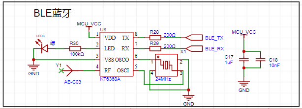
uses BLE Bluetooth for wireless transmission with the computer. I chose the KT6368A to save space.
Wired data transmission might cause the floating ground of the test leads to become grounded, which could easily burn out the circuit.
8. Analog power supply
(Here I divided this schematic into two schematics, one for digital circuitry and one for analog circuitry.
The digital circuitry is divided into many modules; the analog circuitry is connected together, which allows for a more intuitive analysis of the analog front end).
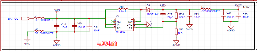
To reduce power supply interference, a series resistor and capacitor can be used to form an RC circuit to further reduce interference in the low-frequency band.
The MT3608 chip was chosen
. The 3D shell is designed based on a board thickness of 1.6mm, so a thickness of 1.6mm was selected when making the board.
I drilled two holes at the end of the 3D shell for attaching a lanyard. I also drilled holes at the corresponding LED positions to facilitate LED display and human-computer interaction.
To ensure a secure mounting of the outer casing to the PCB board, I added a baffle-like structure at the appropriate location to stabilize the PCB board. I also left space below the PCB board
for battery storage. The inner wall height of the upper casing was increased by 1.88mm to accommodate the mounting of the upper and lower casings.
(Actual product shown)
PDF_Multifunctional Test Pen.zip
Altium Multi-functional Test Pen.zip
PADS_Multifunctional Test Pen.zip
BOM_Multifunctional Testing Pen.xlsx
97057
Oscilloscope expansion board based on AFE03
This is an open-source project for an oscilloscope expansion board based on the AFE03, which can turn an STM32H750 development board into an oscilloscope and signal source. It implements functions such as signal conditioning, amplification, shifting, filtering, and comparison, and is compatible with the STM32H750's ADC and DAC.
Project Principle:
This project utilizes analog circuit components such as resistor dividers, operational amplifiers, and comparators to implement signal conditioning, amplification, shifting, filtering, and comparison functions to adapt to the input and output ranges of the STM32H750's ADC and DAC, thus realizing the oscilloscope's sampling and output functions. It also uses switches and voltage divider networks to implement the segmentation function of analog input and output channels, improving the measurement accuracy and output resolution of small signals. Furthermore, it utilizes the STM32H750's timer function to implement triggering and frequency measurement functions.
Project Functionality:
This project can function as a dual-channel oscilloscope, measuring analog signals within a ±15V range and converting them into digital signals within a 0-3.3V range for sampling by the STM32H750's ADC. It can also function as a single-channel signal source, outputting analog signals within a ±10V range, which are then generated by the STM32H750's DAC. It can also square-wave the input signal and utilize comparators and timers to implement triggering and frequency measurement functions.
3D Simulation Diagram:
Oscilloscope expansion board based on AFE03.epro
PDF_Oscilloscope Expansion Board Based on AFE03.zip
Altium_AFE03-based Oscilloscope Expansion Board.zip
PADS_AFE03-based Oscilloscope Expansion Board.zip
BOM_Oscilloscope Expansion Board Based on AFE03.xlsx
97058
Nighttime ambient breathing light
NE555 Melody Light

The switch can be set to either a breathing mode or a constant light mode.
QQ Video 20231121215354.mp4
PDF_Nighttime Ambient Breathing Light.zip
Altium_Nighttime Ambient Breathing Light.zip
PADS_Nighttime Ambient Breathing Light.zip
BOM_Nighttime Ambient Breathing Light.xlsx
97059
[Color Silk Screen Printing] Dual-Color Temperature Magnetic Flashlight - Plain Version
A fun magnetic dorm flashlight with dual-color temperature stepless dimming and a touch switch.
This dual-color temperature stepless dimming magnetic flashlight
is getting straight to the point. Let's show you the finished product – it's incredibly high-quality.

Base plate – Front: Kun Kun Zi (a composite of six images, designed and selected by a random person).
Colorful magnetic back plate
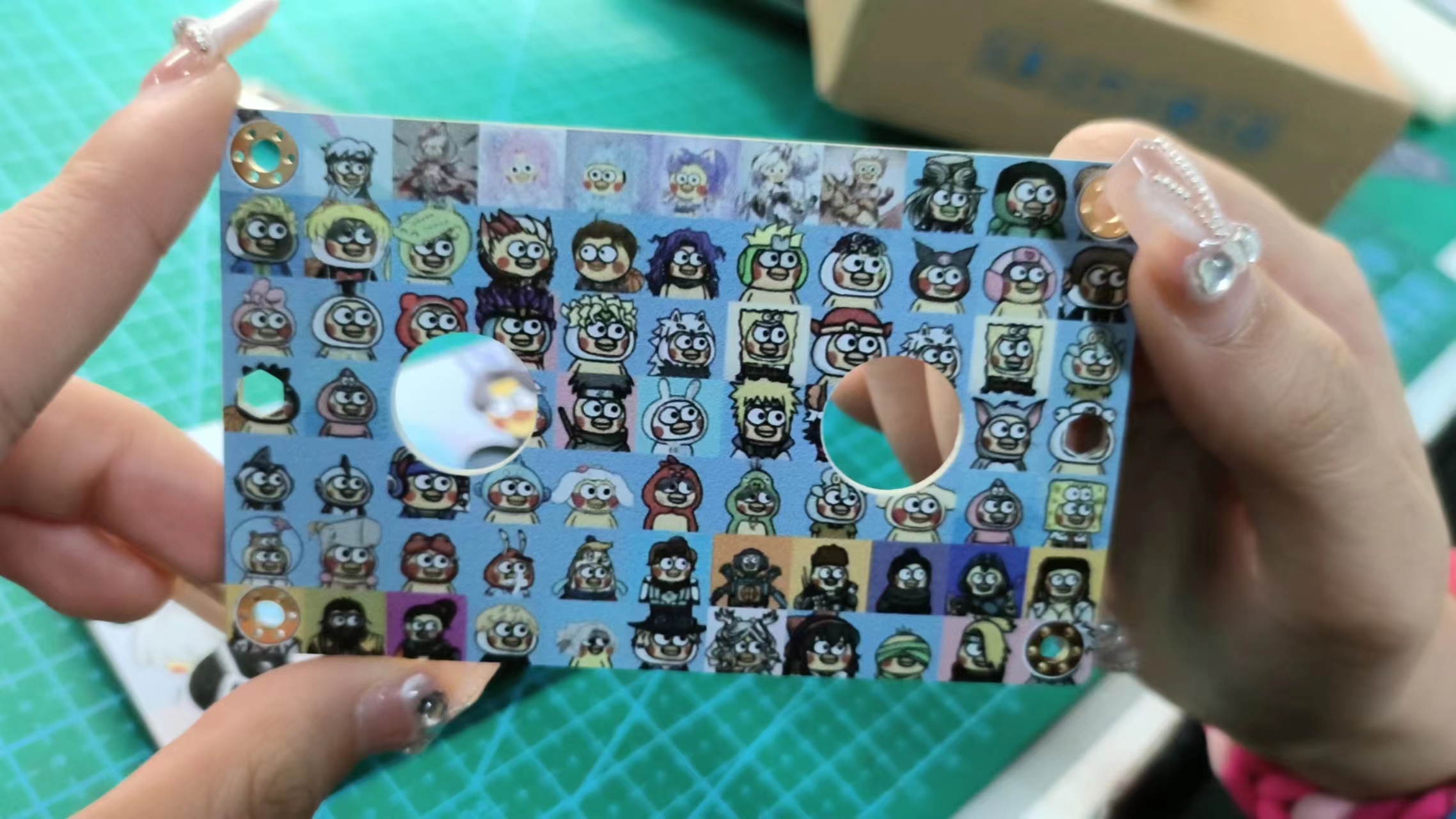
. Base plate – Back: Hundred Kun Zi image.
I must say, the quality of the color screen printing this time is really good; each Kun Kun is clearly visible.
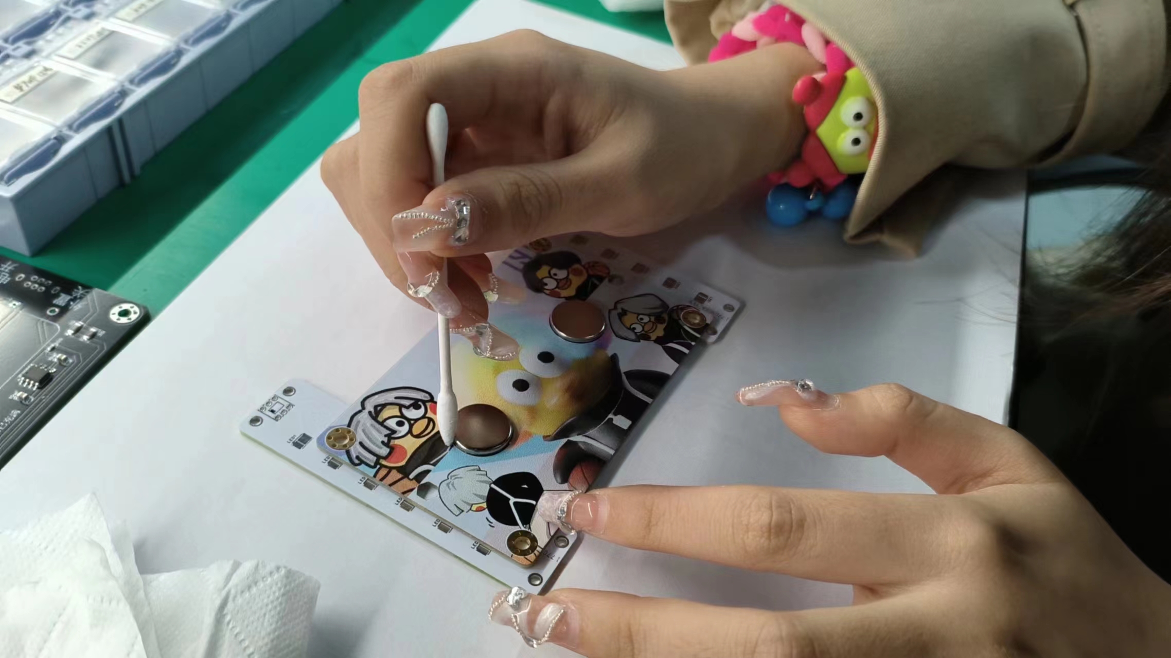
The magnets are
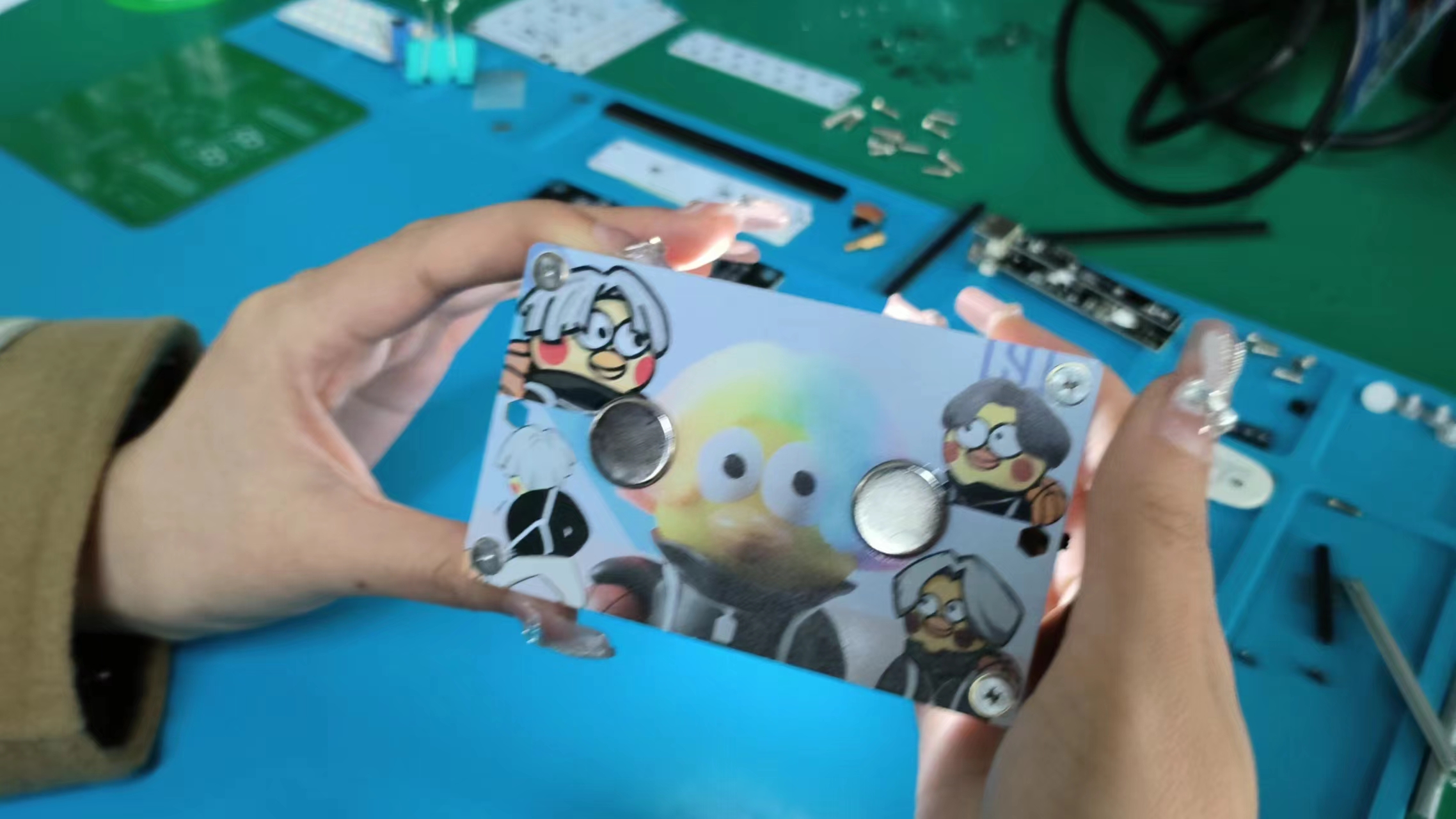
well-glued, and the overall effect meets expectations.
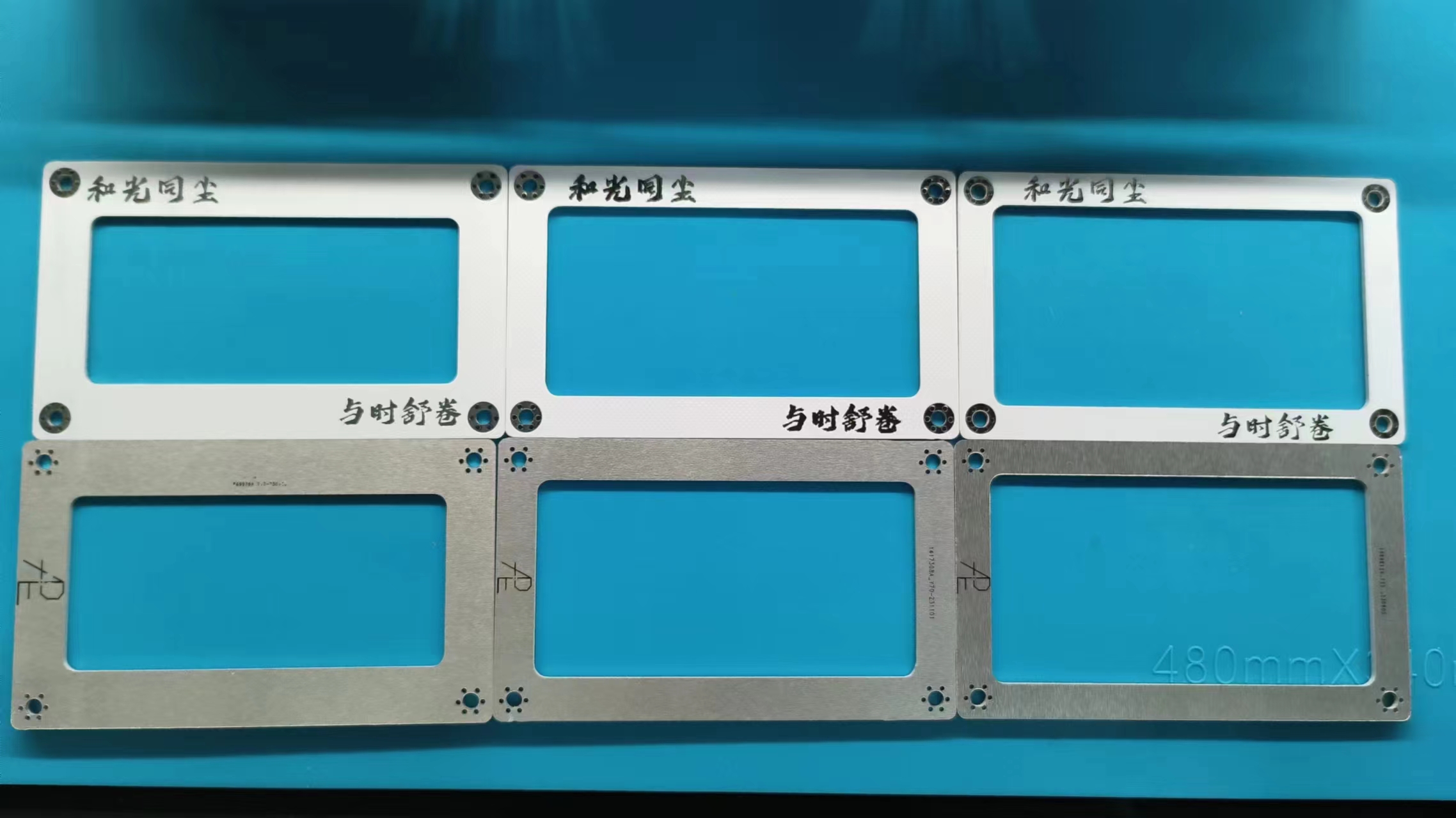
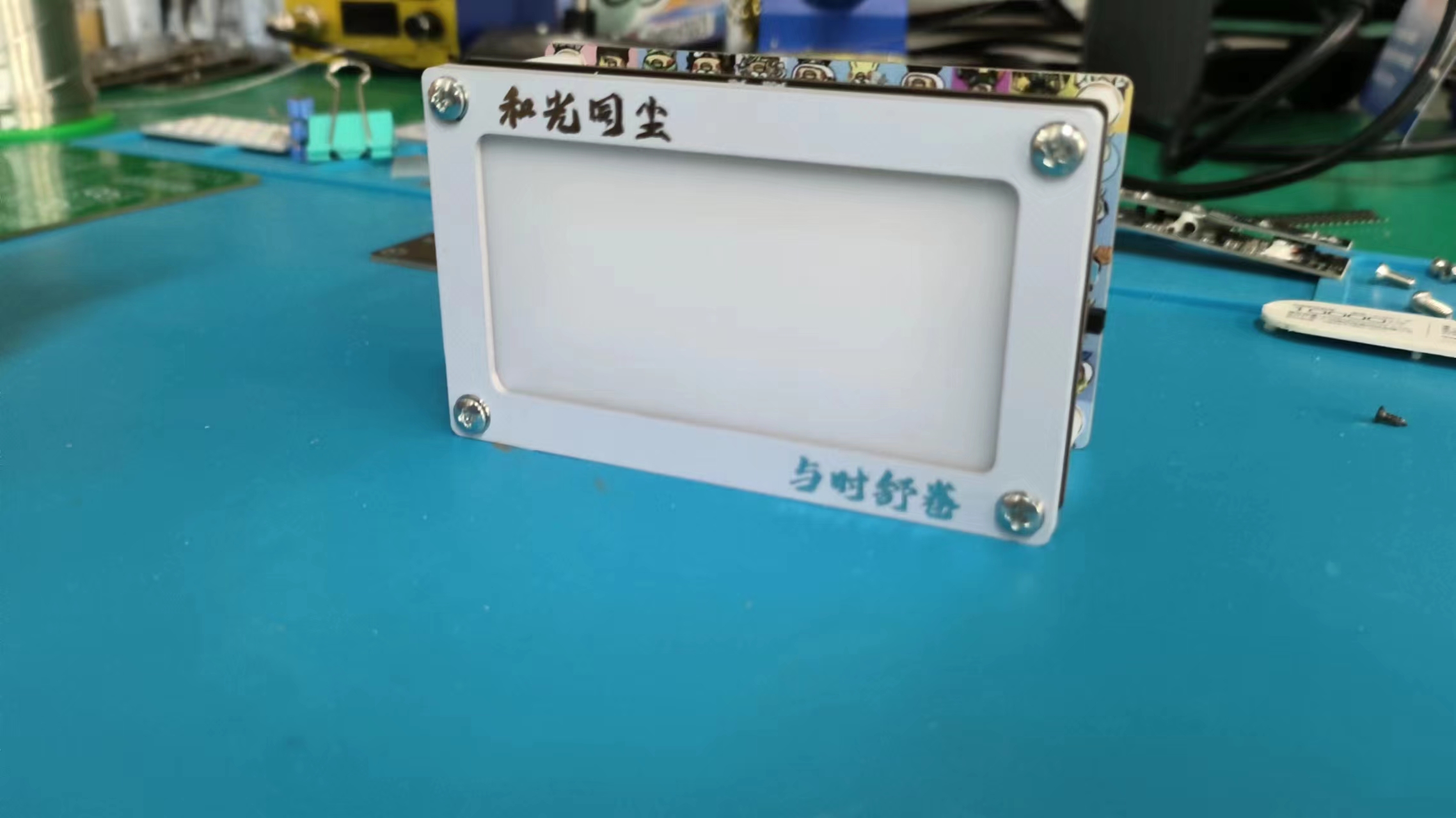
Top plate – "Harmony with the times, unfolding with the times."
I used to like "Unity of knowledge and action," but now I prefer "Harmony with the times, unfolding with the times" as my motto, which I'm sharing with everyone.
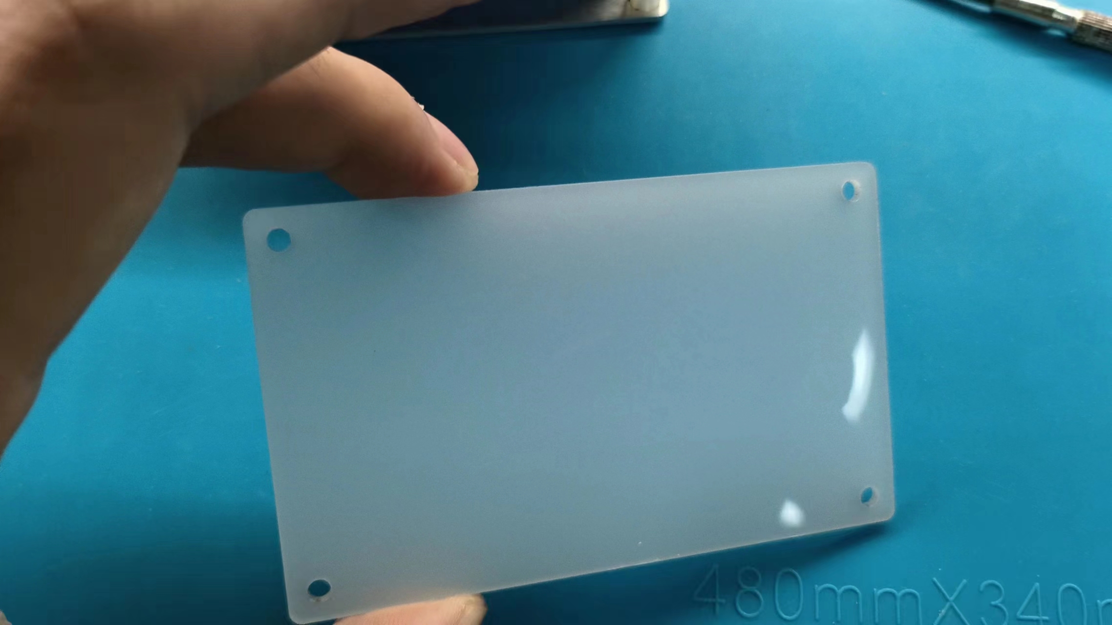
Light distribution board – Produced by JLCPCB panel printing, it has a high-quality feel.

These two pieces are acrylic pieces I found in the trash. I thought the material was good, so I laser-cut them in the lab, and the effect is good.
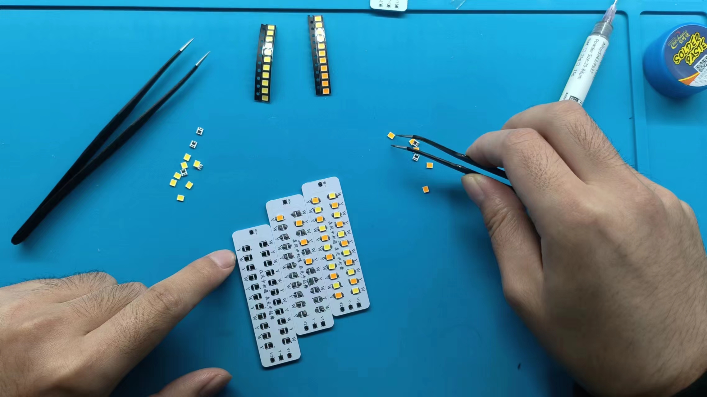
Aluminum-based light board – Excellent heat dissipation; it can't be soldered with a soldering iron, so I have to use a hot plate.
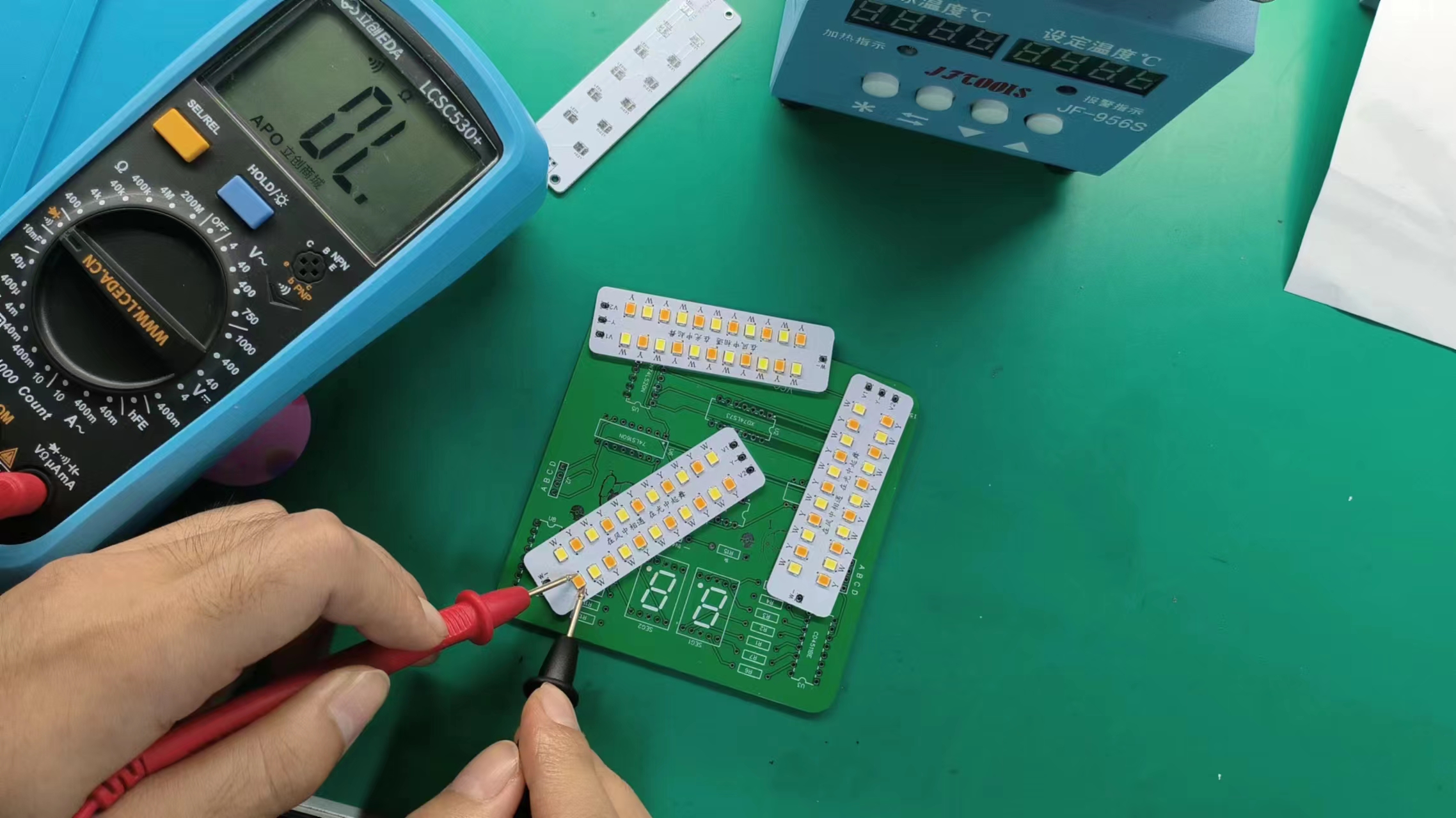
Let's test if too much solder paste was applied.
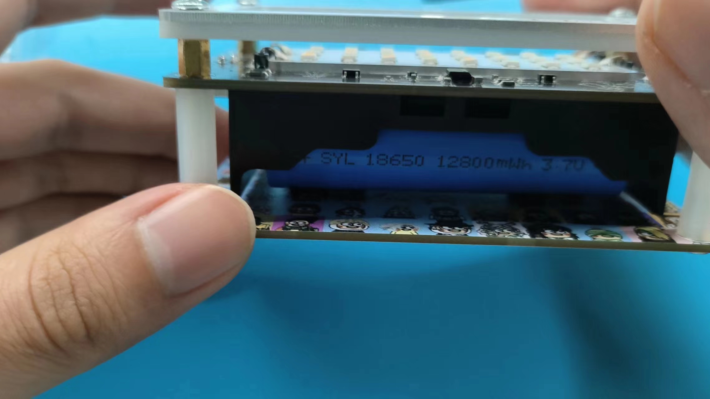
The four-layer PCB uses M3 copper pillars to connect

the two light distribution board effects.

Stand at attention, everyone stand still for the photo (๑•̀ㅁ•́ฅ✧).
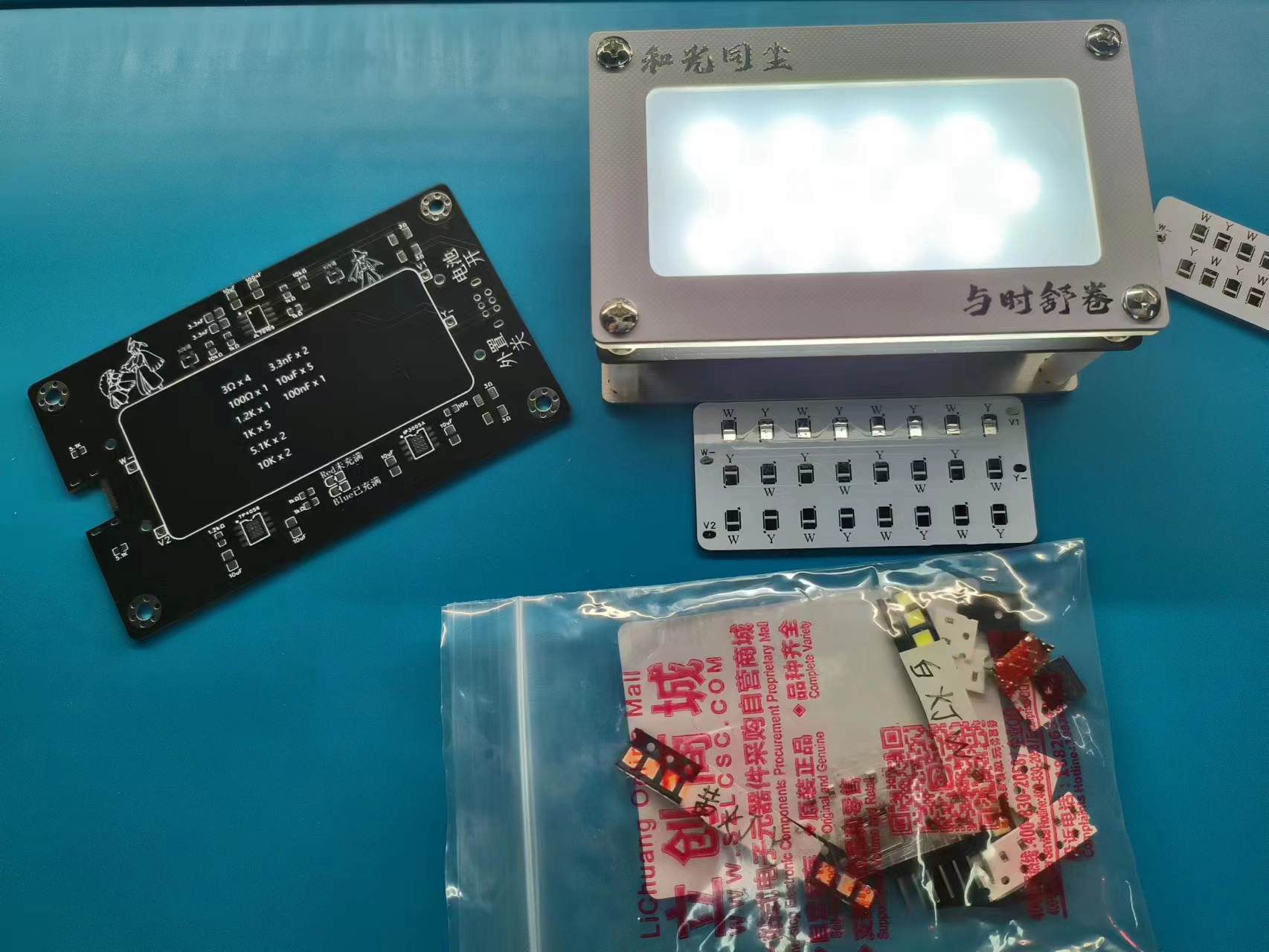
The kit is ready! If you want one, come to my Bilibili Workshop or Xianyu (a second-hand marketplace). Instant purchase, instant payment, instant shipping! ε٩(๑> ₃
DM me on Bilibili, first come, first served (◉ω◉ )

Who doesn't want a super-tight magnetic 'dual-color temperature magnetic touch Kunkun dormitory flashlight'? (ಡωಡ)kunkun——
Color silkscreen display Bilibili link:
https://www.bilibili.com/video/BV1y34y1c7a2/?vd_source=efc8351bbf5e855ebbaee0f1e0636727#reply833668524Lighting
effect display Bilibili link: This video showcases creative DIY welding ideas. (Bilibili link: https://www.bilibili.com/video/BV1PN41147fN/?spm_id_from=333.999.0.0&vd_source=efc8351bbf5e855ebbaee0f1e0636727
)
Back panel assembly demonstration.mp4
PDF_【Color Silkscreen】Dual-Color Temperature Magnetic Flashlight - Plain Passerby Version.zip
Altium_【Color Silkscreen】Dual-Color Temperature Magnetic Flashlight - Purely for Passersby.zip
PADS_【Color Silkscreen】Dual-Color Temperature Magnetic Flashlight - Plain Passerby Version.zip
97060
USB-Serial Dual Type-C STC32-48P Development Board
This board features dual Type-C interfaces, which can fully leverage the advantages of STC32's USB and serial port download capabilities. The pin design allows for easy use of both USB and serial ports. The CH340 also provides a PC-USB connection interface, making it convenient for serial port experiments and debugging.
The STC32-48P development board features dual Type-C interfaces, fully leveraging the advantages of STC32's USB and serial port download capabilities. Its pinout design allows for easy use of both USB and serial ports. The CH340 provides a PC-USB connection interface, facilitating serial port experiments and debugging. The perforated board structure on the back allows for easy connection of peripherals such as OLED displays, keyboards, and digital tube displays.
PDF_USB-Serial Dual Type-C STC32-48P Development Board.zip
Altium_USB-Serial Dual Type-C STC32-48P Development Board.zip
PADS_USB-Serial Dual Type-C STC32-48P Development Board.zip
BOM_USB-Serial Dual Type-C STC32-48P Development Board.xlsx
97061
Digital oscilloscope
Simple digital oscilloscope
Simple Digital Oscilloscope
1. System Power Supply
This project requires four voltage values: +5V, +3.3V, +12V, and -12V. The power supply uses a Type-C data line as the input and a boost converter chip MT3608 (input voltage 2V~24V, output current up to 2A) to convert the input voltage to +15V and -15V. +15V is obtained by passing through a 78L12 to get +12V, +15V is obtained by passing through a 78L05 to get +5V, and -15V is obtained by passing through a 79L12 to get -12V. As for +3.3V, it is obtained by using the classic AMS1117. (VBUS is +5V)
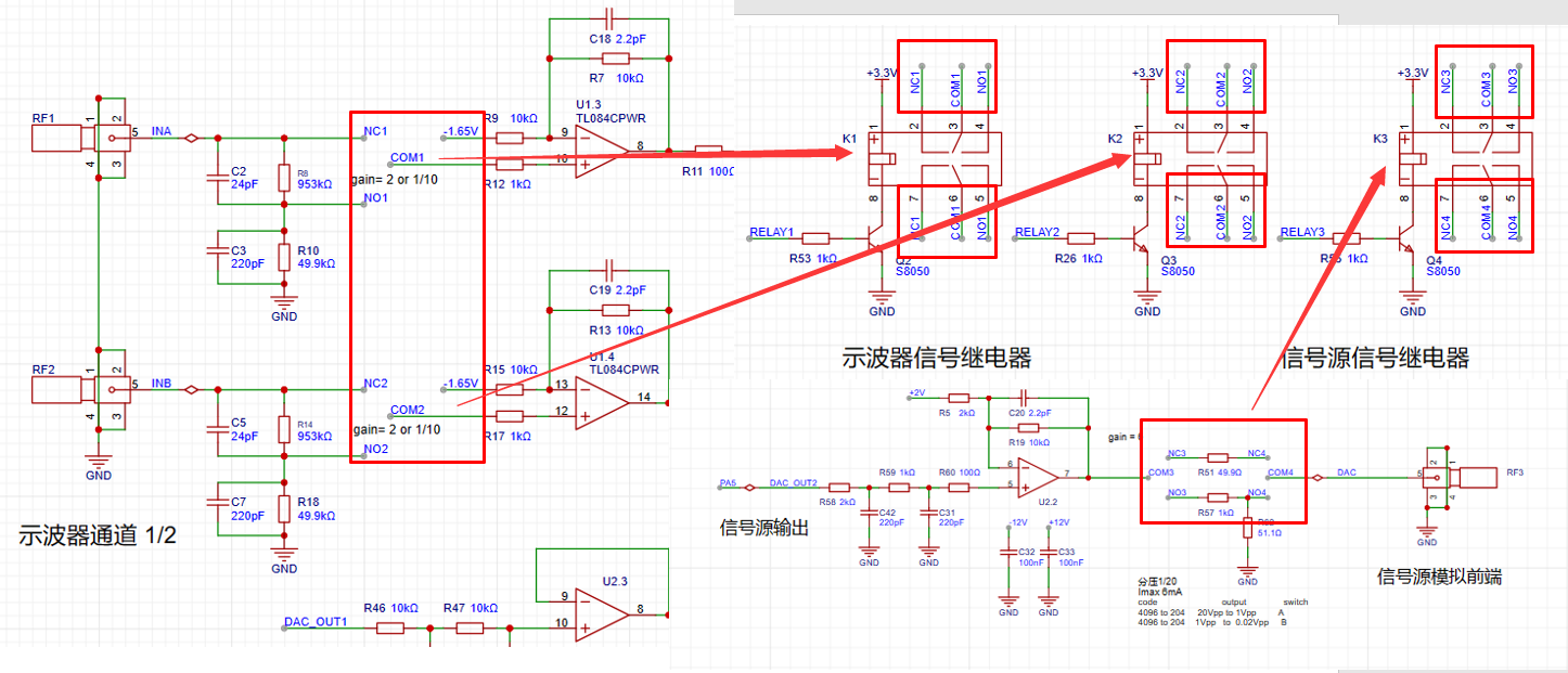
2. The analog input channel
expansion board provides two oscilloscope input channels, as shown in the figure below. It includes signal conditioning implemented by resistor voltage divider and operational amplifier, and square wave output implemented by comparator (for triggering and frequency measurement).
INA and INB are the two input terminals of the oscilloscope. The analog input signal is connected to the positive pin of the SMA straight connector here. The input impedance of 1MΩ is achieved by series voltage divider through resistors (953K and 49.9K) and two signals are generated for selection: one input is direct and the other is attenuated to 1/20.
The operational amplifier uses a TL084 (integrated quad op-amp), powered by dual +12V and -12V power supplies;
AnalogA and AnalogB: Analog signals amplified and shifted by the inverting amplifier are connected to the STM32H750 development board and sampled by the H750's ADC;
TrigerA and TrigerB: Square wave signals generated by AnalogA, AnalogB, and a DC reference level (generated by one of the H750's DACs) after passing through a comparator, are input to the STM32H750's timer for frequency measurement;
DAC_OUT1: DC reference level, output through the STM32H750's internal DAC configuration.

First, we know that when the VREF of the STM32H750 is powered by 3.3V, the input range of the STM32's ADC is 0-3.3V. However, our input signal has a maximum range of ±15V. Therefore, we need to solve the problem of large signal input not being saturated. Let's solve an equation:
15 * a + b = 3.3;
-15 * a + b = 0;
We can get a=0.11, b=1.65;
That is to say, we need to attenuate the input signal to at least 0.11 times (approximately 1/9) and add 1.65V DC to meet the full-scale input of the ADC sampling.

According to the superposition theorem, we first analyze the contribution of the input signal AIN to the output Vo. By grounding the other voltage source in the circuit, -1.65V, the input signal is divided to 1/20 after passing through R8 (953K) and R10 (49.9K), and then amplified by a factor of 2 by the non-inverting amplifier circuit. The overall gain of the input signal is 1/10. When analyzing the contribution of DC -1.65V to the output Vo, with the input signal AIN grounded, the amplification factor of -1.65V is -1. Therefore, the output Vo = -1.65V * (-1) + AIN/10 = 1.65V + AIN/10.
The -1.65V voltage is generated by the following circuit;

having solved the problem of matching the ±15V input to the 0-3.3V input range of the ADC, we also need to consider the problem of accurate sampling even when the input signal is small. For example, when a 10mV signal is input, it will attenuate to 1mV after passing through the above circuit. To ensure the signal-to-noise ratio of the input signal as much as possible, we add a switching mode to the analog front end. When sampling a small signal, we use a switch to select the direct INA signal to the non-inverting input of the op-amp, instead of selecting the signal attenuated by INA to enter the non-inverting input of the op-amp. This ensures that the signal entering the ADC is as large as possible. Combined with a 16-bit ADC, the sampling results can be accurate and reliable.
3. The analog output channel
expansion board provides one signal output channel, as shown in the figure below, including resistor voltage divider and signal conditioning implemented by operational amplifier;
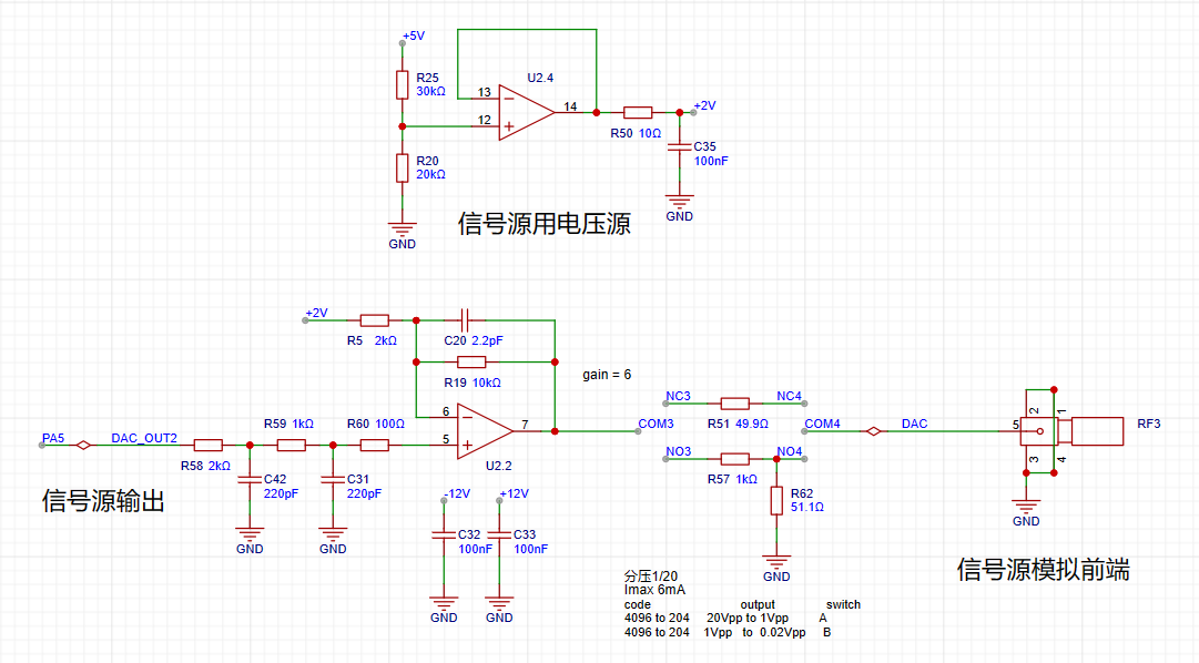
we know that when the VREF of the STM32H750 is powered by 3.3V, the output range of the internal DAC is 0-3.3V. To achieve ±10V output, we need to solve the equations:
0*a + b = -10V;
3.3*a + b = 10V;
Solving for a=6.06, b=-10;
In the diagram above, the 0-3.3V signal output from the DAC (PA5) inside the STM32H750 is passed through a two-stage RC low-pass filter and then input to the non-inverting input of the TL084, forming a non-inverting amplifier with a gain of 6. After amplification, the waveform is 0-19.8V; Then, using the -5x amplification capability of the inverting amplifier section of the TL084, the +2V obtained by voltage division of 5V is amplified by -5x to obtain -10V, which is superimposed with the 0-19.8V signal output from the non-inverting amplifier to obtain an output of approximately ±10V. The calculation formula is: Vout = -10 + 6*Vin.
4. Comparator Circuit
The comparator uses an LM393 (dual-channel), powered by +5V; In order to realize the trigger function and frequency counter function, we designed two comparator channels on the board to convert the waveforms of the two analog input channels before entering the ADC into square wave signals for use as timer inputs of the H750. The reason for using the waveform before entering the ADC for comparison is that the waveform entering the ADC has been conditioned by the front-end analog circuit and falls within the known 0-3.3V range, making the comparator's comparison threshold easier to design.

As shown in the diagram above, the H750 uses its internal DAC to output a 0-3.3V DC signal to compare with the waveform of channel 2 before entering the ADC, converting the channel 2 waveform into a square wave. This allows the H750's timer function to use the square wave signal for interrupt handling and timer capture.
5. Channel selection
uses a relay as a selection switch to select either a direct signal or a signal attenuated to 1/20th of its input to the first-stage non-inverting amplifier. The non-inverting amplifier performs two tasks: first, it amplifies the input signal at the non-inverting input by a factor of two; second, it shifts the amplified signal by 1.65V, calculated as Vo = 1.65 + 2*Vi.
A signal switch (relay or manual switch) is added after the 1M ohm input voltage divider resistor to select whether the AIN signal enters the op-amp's non-inverting input directly or after being divided to 1/20th of its input. For both methods, the input impedance for the AIN signal is 1M ohms. When we need to acquire small signals, we can toggle the switch to use the direct input to obtain more accurate measurement results. We can calculate that when the direct input is selected, Vo = 2*AIN + 1.65, while when the attenuation input is selected, Vo = AIN/10 + 1.65. Therefore, the overall gain of the corresponding circuit is 2 times or 1/10 times.
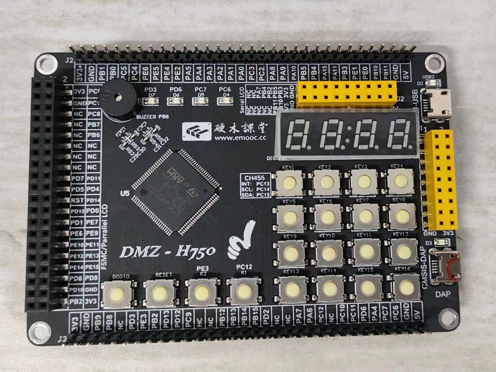
The signal source relay uses a voltage divider network to achieve good results when outputting small signals using analog circuit voltage division. Similar to an ADC, the DAC's resolution is a problem in order to cover the signal source output from ±10mV to ±10V while balancing a large signal range and small signal accuracy. The H750's DAC is 12-bit, and its full-scale output (when all 4096 code values are used) is ±10V. When we reduce the DAC code value to output a small signal, to achieve a waveform voltage resolution of 7 bits (i.e., a vertical resolution of 128 points), the waveform must be attenuated by 128/4096 = 1/32. Converted to an output voltage range of ±10V/32 = ±0.3215V, for signals smaller than ±0.3125V, further reducing the code value will result in insufficient DAC resolution and noticeable waveform step-offs. Therefore, we used an analog voltage divider approach. When outputting signals smaller than ±0.3125V, we used a switching resistor divider to attenuate the waveform by 1/20, ensuring voltage resolution for small signals. Simultaneously, the combination of R57 and R62 ensures the output resistance is 50Ω at 1/20 attenuation, and R51 ensures the output resistance is 50Ω at x1. This is used
with the Hardwood Classroom H750 core board, as shown in the diagram below:
PDF_DigitalOscilloscope.zip
Altium Digital Oscilloscope.zip
PADS_DigitalOscilloscope.zip
BOM_DigitalOscilloscope.xlsx
97062
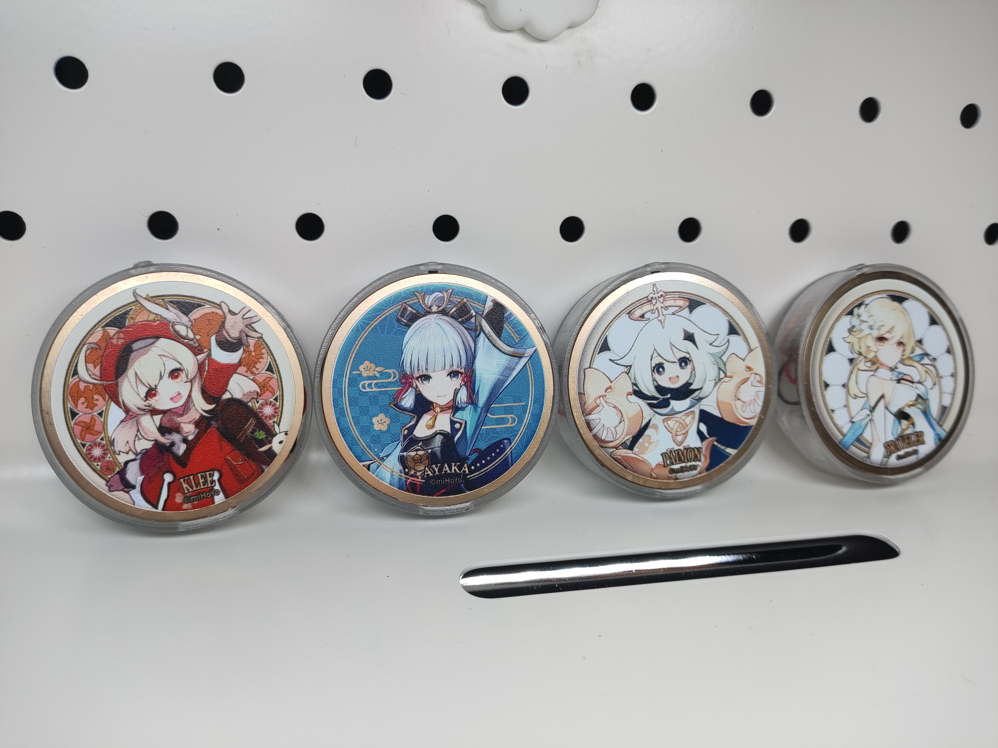
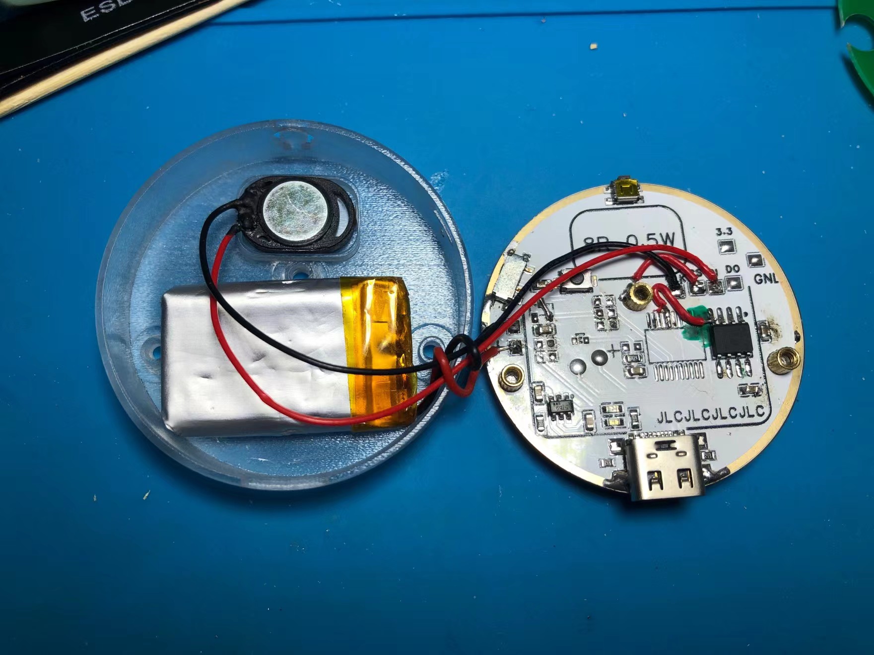
[Color Silkscreen Printing] Genshin Impact Transformation Device [Voice Playback]
Genshin Impact Transformation Driver
The Genshin Impact transformation device
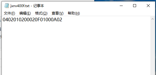
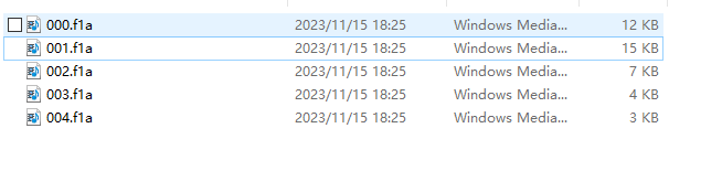
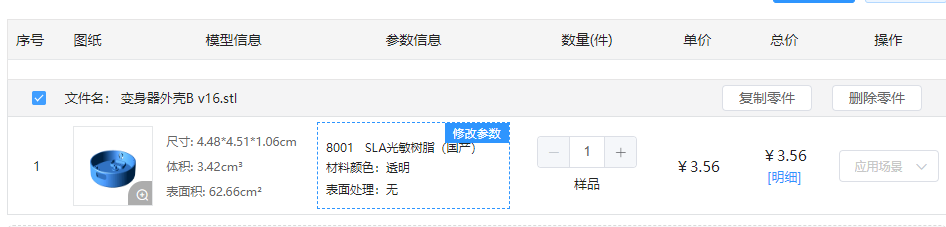
is now complete . The design is inspired by the Kamen Rider transformation device and incorporates its features. The pattern is from the official badge stickers released by miHoYo; other patterns can be used as needed. It uses the reprogrammable chip WT588D-20SS, which is readily available and easy to use (but has been discontinued due to its age and inability to be driven after downloading). A nine-core NV400F chip has been replaced. Single-piece and four-piece prototypes were created within the project. The four-piece prototype requires manual cutting but is more cost-effective. Printing is optional. The board features a pure bottom-layer layout with no vias. To ensure a complete top surface soldering, the positioning posts for the Type-C port, switch, and buttons need to be cut off. The images below are from the old version; the new PCB has been redrawn. Operation: Pressing the top button produces a sound effect. The board is only designed for single-button operation, but multi-button operation and programming are possible; modifications can be made if needed. The burning tutorial and software file are too large to upload. They have been uploaded to Baidu Cloud via this link: https://pan.baidu.com/s/17g81MBAu6D0OjQcWWzcYtQ?pwd=td40 Extraction code: td40. The official TTL burning tutorial verification failed; an offline dongle is used for burning. The dongle needs to be purchased separately. [Offline Dongle Copying] The audio conversion software in the package converts MP3 audio to FLA format. Import all audio files and command txt files into the offline dongle. The key command is "down". The format must start from 000, otherwise it will not be recognized . Due to space limitations on the PCB , various coil types were tested. A single coil can be recognized, but after adding a battery, the coil cannot be recognized because the battery shields the operation. Neither of the two PCBs in the project could be used, so a self-made coil was finally used. The phone can recognize the device after adding a battery in the project. The outer shell is made of 3D transparent 8001 stainless steel. The version shown in the project is without chamfering and logo. The STL file in the link has been refined; you can choose to print it yourself. Fasteners: 3 M2 screws , 6 M2 knurled nuts (just align them). Battery: C5182591 , size 402030. You can purchase this yourself. For the project, you can choose a smaller battery from LCSC. Speaker: C530539 GSPK151035PN-8R0.5W-L35-1.25T chip, can directly drive an 8R0.5W speaker. You can purchase this yourself. Other power ratings like 1W and 0.7W can also be driven. Video: https://www.bilibili.com/video/BV18N411u7Hr/?spm_id_from=333.999.0.0


3DShell_3DShell_the board is here, this is the one_B v6.stl
fb866a4dfd2578ca98d06a58ca9576bb.mp4
PDF_【Color Silkscreen】Genshin Impact Transformation Tool【Voice Playback】.zip
Altium_【Color Silkscreen】Genshin Impact Transformation Tool【Voice Playback】.zip
PADS_【Color Silkscreen】Genshin Impact Transformation Tool【Voice Playback】.zip
BOM_【Color Silkscreen】Genshin Impact Transformation Tool【Voice Playback】.xlsx
97063
electronic


 京公网安备 11010802033920号

 BEFSCA1


