① Voltage measurement + threshold judgment: the threshold level can be set according to requirements to meet different logic level scenarios, and retains the useful traffic light indication function of the "simple logic level test pen";
② Continuity measurement: the threshold resistance can be adjusted according to requirements;
③ Diode measurement: lights up a diode;
④ PWM output: provides a known quantity for system testing in some scenarios, and can also be used to test passive buzzers, etc.;
⑤ PWM input: can measure frequency;
⑥ DC output: simulates a required DC level for testing.
PDF_Multifunctional Test Pen Based on CW32F030.zip
Altium_Multifunctional Test Pen Based on CW32F030.zip
PADS_Multifunctional Test Pen Based on CW32F030.zip
BOM_Multifunctional Test Pen Based on CW32F030.xlsx
97077
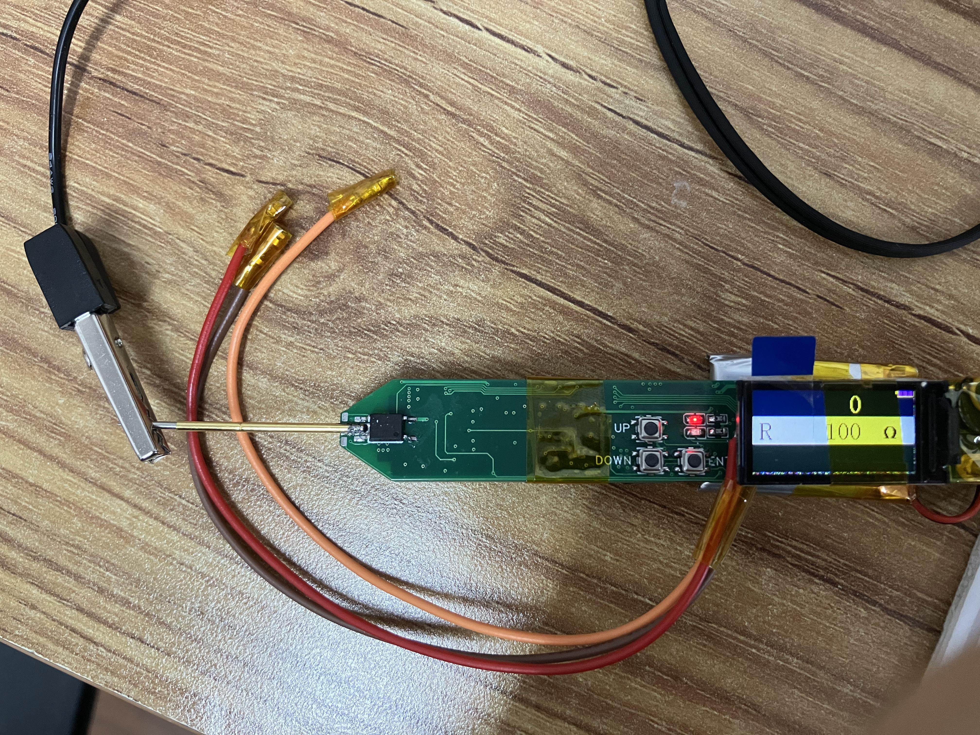
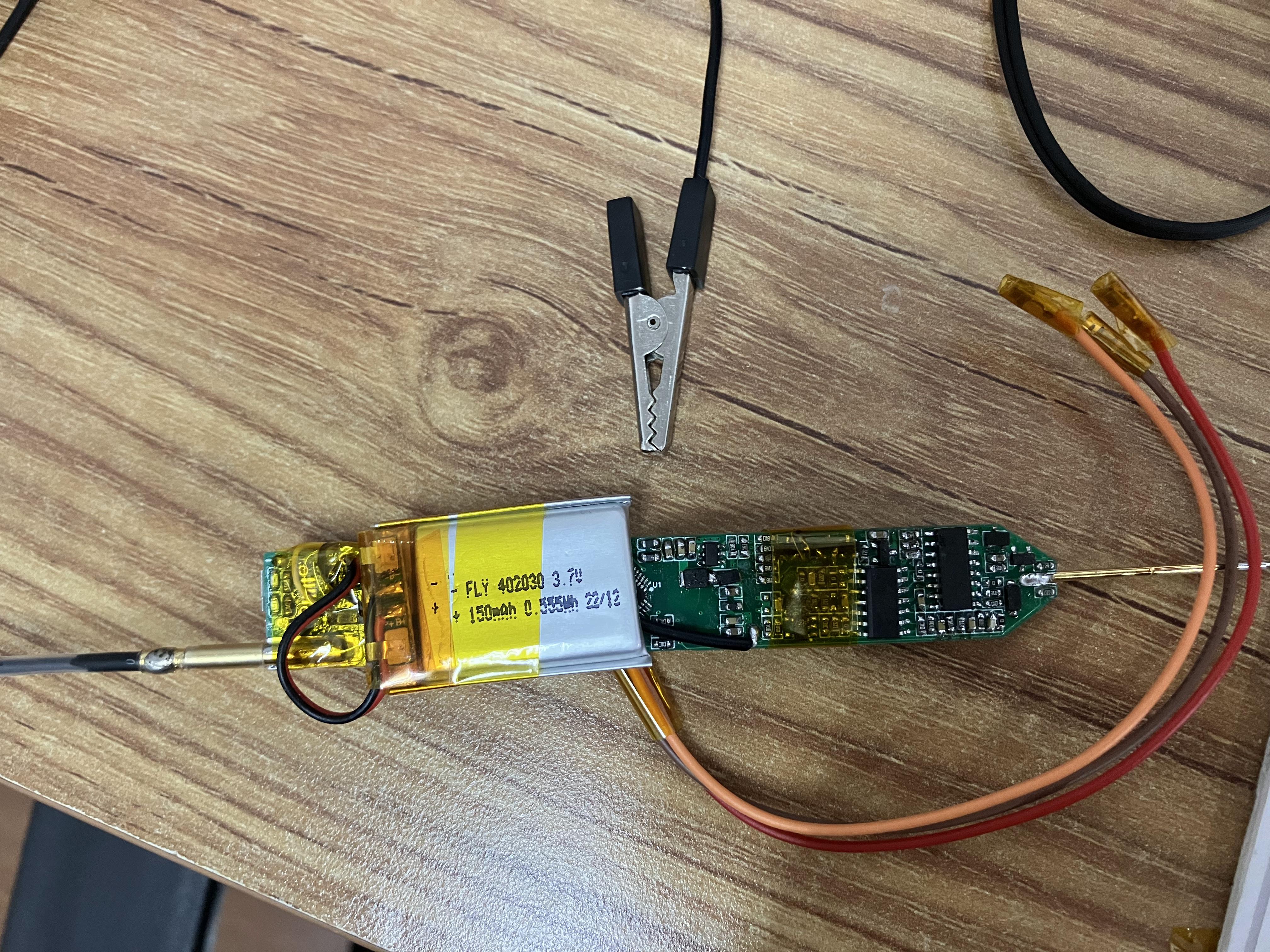
Magic Pen
The Magic Pen: A project inspired by the LCSC training camp.
This is a project inspired by the LCSC training camp. It involves a large number of circuit components, making it a significant challenge for beginners. The components have been soldered. Power-on testing is successful, so it's considered verified. Further testing will follow. I've uploaded a power-on video; please provide feedback. (I couldn't properly crop the images to scale.)
Hong3.jpg
Hong4.jpg
Power-on video.mp4
PDF_Magic Pen.zip
Altium_Magic Pen.zip
PADS_Magic Pen.zip
BOM_Magic Pen.xlsx
97078
Simple Digital Oscilloscope
Simple Digital Oscilloscope
Attention! The USB used is a surface mount package. When soldering, be careful not to solder the fixing pins poorly.
First,
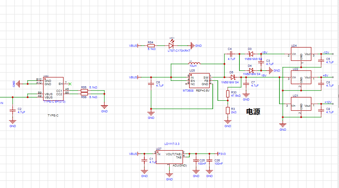
when soldering the power supply section, solder the power supply first. Test whether the output voltage meets the requirements. The 3.3 regulated power supply uses an ams1117. The two filter capacitors can be tantalum capacitors

. The pin packages of 79L12, 78L12 and 78L05 are different. Please pay attention to the difference. At the same time, pay attention to the temperature during soldering, otherwise the power chip may be damaged.
II.
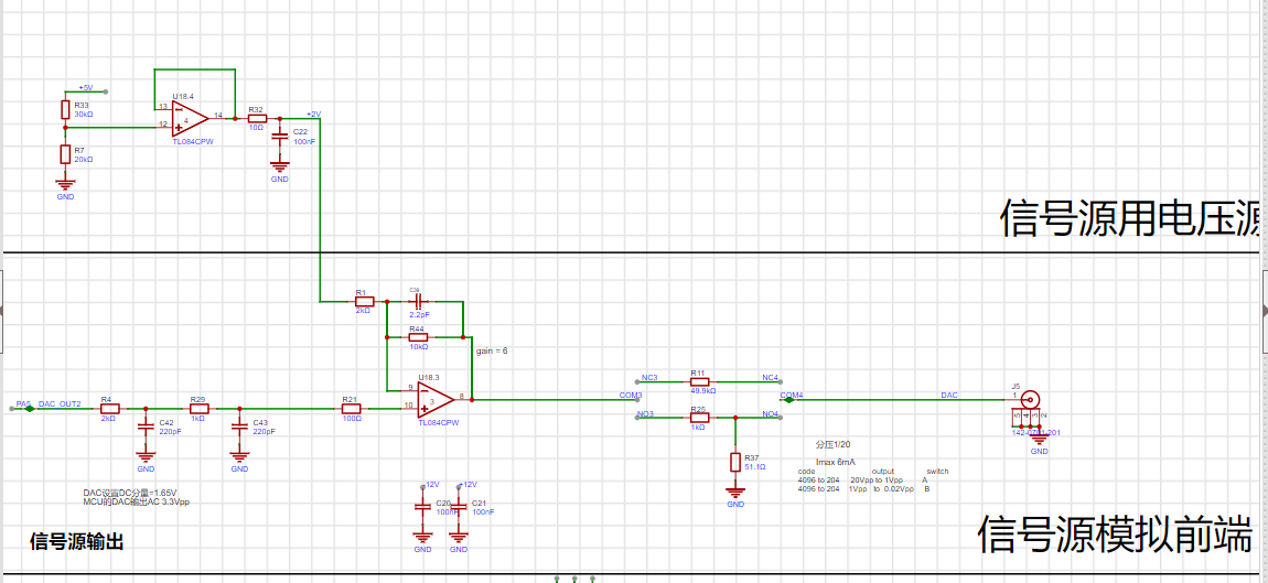
The compensation capacitors of the analog input channel may affect the peak-to-peak measurement. You can choose not to solder them. For relevant information, please refer to the project published by Hardwood Classroom:
[Hardwood Classroom] AFE03 Oscilloscope Signal Source Expansion Board
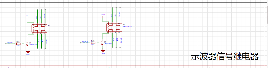
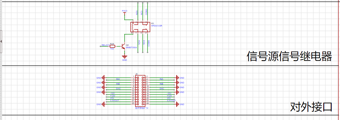
. III. Pin Assignment: The pin
assignment is the same as the project published by Hardwood Classroom, except for some differences in the button and relay pins. You only need to change the port in the code published by Hardwood Classroom to download and use it.
UKEY2: PB2 --> PB7
UKEY3: PD13 --> PB6
UKEY4: PD12 --> PD7
RELAY3: PB8 --> PE7
IV. Housing :
Pay attention to the size when purchasing buttons and encoders, otherwise they may not be able to be installed. If you want to use different models of BNC interfaces, buttons, or encoders, you need to modify the 3D housing.
If you need to install keycaps, you need to modify the top button slot.
VID_20231119142322.mp4
Oscilloscope software.zip
PDF_Simple Digital Oscilloscope.zip
Altium Simple Digital Oscilloscope.zip
PADS_Simple Digital Oscilloscope.zip
BOM_Simple Digital Oscilloscope.xlsx
97079
clock ws2812
A network clock made using ESP-01S and WS2812 LEDs
I recently learned about controlling WS2812 LEDs and discovered that the ESP8266 has a standard control library file. I tried using the ESP-01S module to control the WS2812 LEDs to make a disc clock. Following the principle of taking advantage of any opportunity, I divided the entire disc clock into several circuit boards no larger than 10cm x 10cm. Then, utilizing the ESP-01S's Wi-Fi function, I created a network clock.
1. Each LED circuit board contains 17 LEDs connected in series and powered by 5V. Each circuit board has a DIN and DOUT interface.
2. The DIN pin of the LED circuit board connects to the DOUT pin of the next LED. The 12 circuit boards are soldered into a disc. An ESP-01S control baseboard is soldered onto the first circuit board.
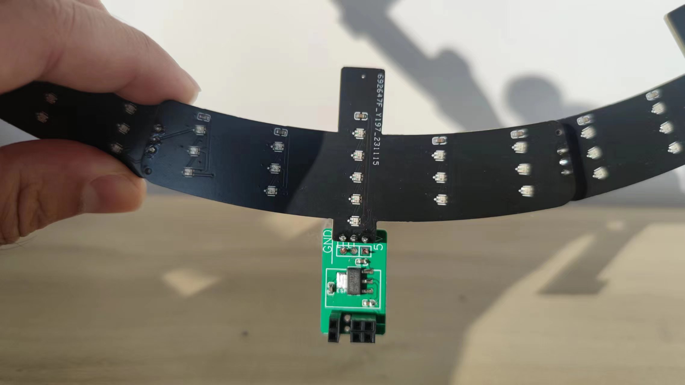
3. The DIN pins of the first circuit board are not soldered to the previous circuit board.

(Discussion:)
1. The final result is slightly different from what I imagined. However, controlling the WS2812 can achieve a more impressive effect. I've uploaded the code for implementing the video function (requires Wi-Fi configuration), which you can modify according to your own ideas.
2. The entire watch face would look even better with a brown acrylic disc.
3. I haven't calculated the power consumption, so I don't know if it will be very power-intensive. I'm currently using a scrap USB cable for 5V power supply; I don't know if using a battery would be feasible
. Additional note:
I found that using a power bank for power consumption was quite high. Later, I saw that the ESP8266 has three low-power modes. In ModemSleep mode, the CPU can still work, so after obtaining the time, I used
the `WiFi.forceSleepBegin();` instruction, and then used a 1-second timer to wake up at midnight every day to recalibrate the time and then sleep again. I don't know how effective this is at saving power. New code: clock.ino
ws2812 clock.mp4
ws2812.ino
clock.ino
PDF_Clock ws2812.zip
Altium_clock_ws2812.zip
PADS_clock ws2812.zip
BOM_clock_ws2812.xlsx
97080
Simple Digital Oscilloscope
This project is a replica of the Hardwood Classroom AFE03 oscilloscope and signal source expansion board, used with the Hardwood Classroom STM32H750 core board. I/O allocation is only applicable to the H750 core board. Please refer to the schematic diagram for specific allocation details.
The requirements
are to build an oscilloscope (or oscilloscope expansion board) that meets the following basic specifications:
±10V dual-channel 2M sampling rate or higher, 20k bandwidth,
sine wave peak-to-peak measurement error no greater than 5%,
range switching function (switching control method is not limited)
, stable triggering, no obvious slippage,
frequency measurement error no greater than 5%
, ±4V 20k output, square wave, triangle wave, sine wave
, sine wave, and square wave peak-to-peak error no greater than 15% .
The schematic design is
based on the official schematic from Hardwood Classroom, with modifications. Below are images of the schematics for each part.
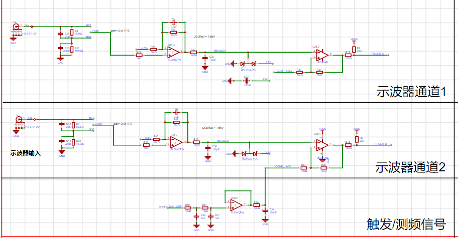
Important Notes:
I encountered many difficulties during the construction process, such as soldering. This was one of the few times I soldered surface mount components, so I was very slow at first, but I gradually mastered the techniques.
For example: 1. Don't add too much solder paste. 2. Buy a small blade tip for the soldering iron, as this is more conducive to soldering surface mount components. 3. Be careful to avoid cold solder joints. 4. Be extra careful with components with many pins. I was particularly impressed by the screen socket; buy several to avoid solder bridging. 5. Don't set the soldering iron temperature too high. Also, regarding the purchase process, I checked the BOM list item by item and changed it to JLCPCB.
During testing, I encountered many problems, such as incorrect resistor values, cold solder joints, and short circuits. I checked each problem step by step with a multimeter and finally found the error.
WeChat_20231120200509.mp4
PDF_Simple Digital Oscilloscope.zip
Altium Simple Digital Oscilloscope.zip
PADS_Simple Digital Oscilloscope.zip
BOM_Simple Digital Oscilloscope.xlsx
97081
16-bit high-precision ADC
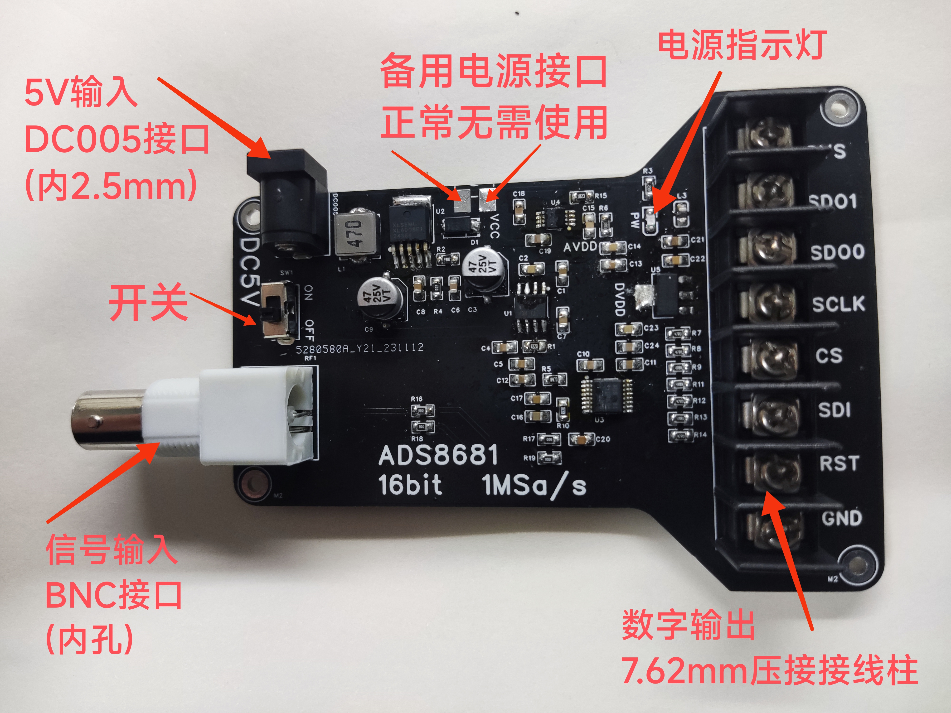
ADS8681 16-bit high-precision ADC, 1Msa/s.
Analog input interface: BNC (internal hole).
Digital output interface: 7.62mm terminal block.
Power supply: DC005 connector (internal 2.5mm), DC 5V input
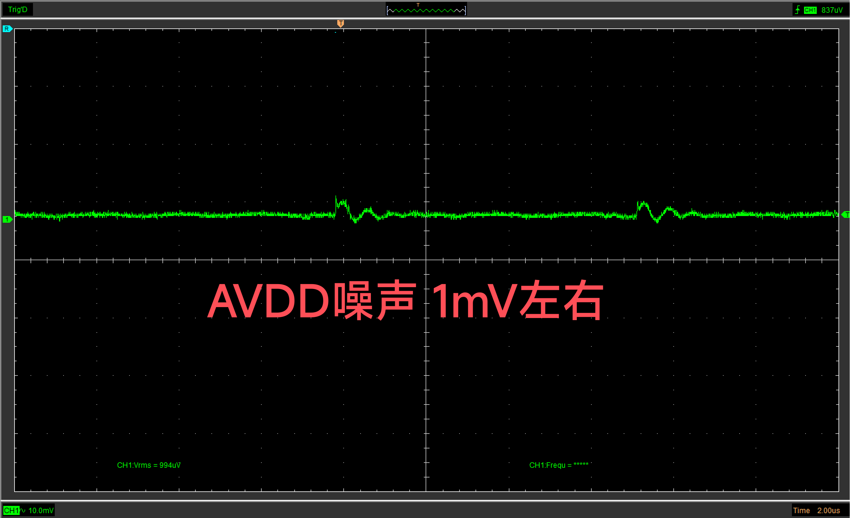
, with noise interference fully considered.
The PCB layout design separates
the switching power supply, analog circuits, and digital circuits,
clearly distinguishing between power ground, analog ground, and digital ground. Each ground is connected at a single point (analog ground and digital ground are connected to power ground via vias, with no pressure difference between the ground planes) to reduce crosstalk.
Analog input ports and digital output ports are isolated by maximum distance and located on opposite sides of the PCB.
Noise interference is fully considered through ground partitioning, RC oscillation absorption, separate analog and digital LDOs, and LC decoupling. The main components for
power supply noise level are: ADS8681 (16-bit resolution, 1 MSa/s, multiSPI™ communication (compatible with traditional SPI)); and an XL6008 main power supply. The BOOST switching power supply is divided into two paths: an analog power supply (TPS7A4901) and a digital power supply (AMS1117) . This design aims to minimize the interference of digital switching noise on the analog components while ensuring convenient power supply. The analog power supply uses the ultra-low noise TPS7A4901 to reduce analog noise and ensure the true accuracy of the ADC. The digital power supply uses the AMS1117 (low cost and meets requirements), with LC filtering at the input port to decouple high-frequency noise and prevent it from coupling to the analog components through the LDO. Module Description
PDF_16bit High Precision ADC.zip
Altium_16bit High Precision ADC.zip
PADS_16bit High Precision ADC.zip
BOM_16bit High Precision ADC.xlsx
97082
ST7789 Dedicated Driver Adapter Board
Basically, it's a stupid circuit board, suitable for Lao Wang's 240*240 ST7789 color screen.
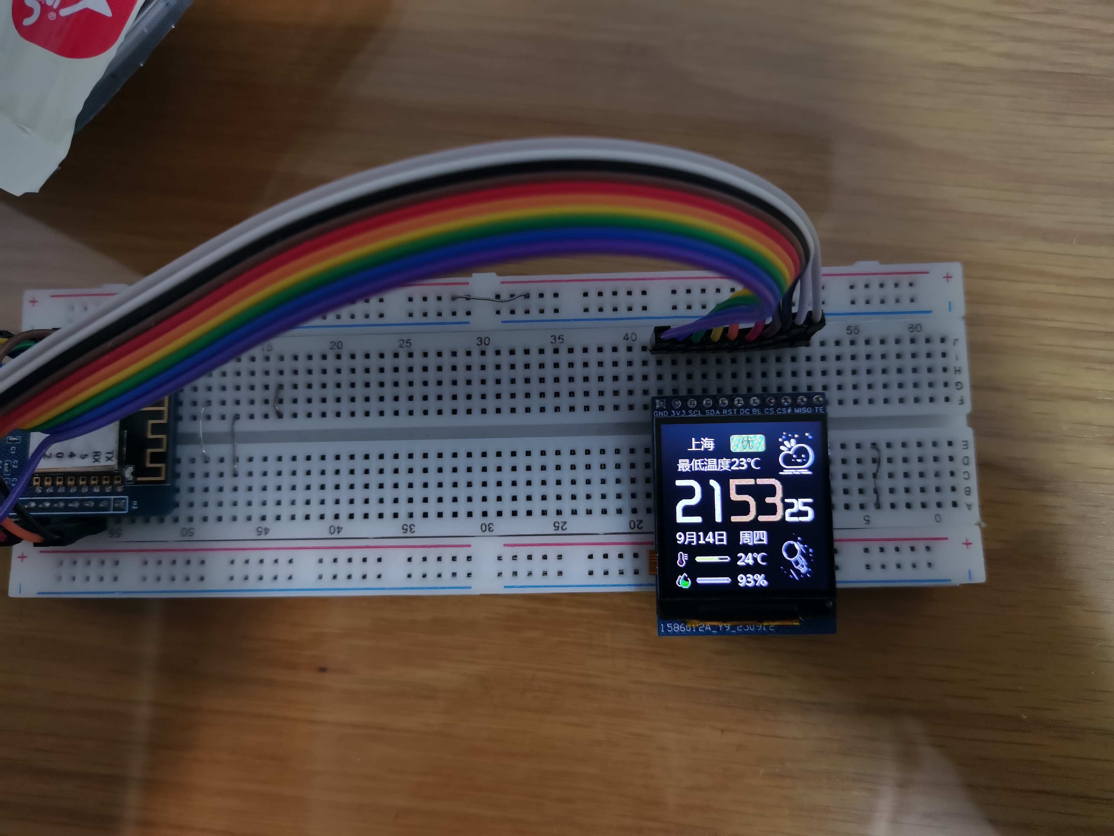
ST7789 screen adapter board
based on Lao Wang's 1.4-inch LCD screen: [Taobao] https://m.tb.cn/h.5UfeXRG?tk=YYPwWaLsaOI CZ0001 "240*240 color screen driver ST7789, no data available, brand new"
Main controller: ST7789
Resolution: 240*240
Screen size: 1.4in
Voltage: 3.3V
Not an IPS screen
with integrated Chinese character library. A group member helped write the driver, which is attached.
When using the TFT-eSPI library, you need to disable the color
inverter. The position of the connector seems to be slightly too high, which is a bit of a strain on the ribbon cable.
The screen brightness is low, and it may be necessary to replace the backlight driver IC. Currently, it works fine indoors.
STM32F103C8T6_SPI st7789 + font library (1).zip
PDF_ST7789 Dedicated Driver Adapter Board.zip
Altium_ST7789 Dedicated Driver Adapter Board.zip
PADS_ST7789 Dedicated Driver Adapter Board.zip
BOM_ST7789 Dedicated Driver Adapter Board.xlsx
97083
electronic


 京公网安备 11010802033920号

 NTE5606


