 2. PS7516 Boost Circuit, Voltage Detection Circuit, and Soft-Start Circuit:
  An external 3.7V lithium battery can be connected to power the entire circuit board, or a Type-C power supply can be used. The Type-C interface can also be used to charge the circuit board. The specific circuit diagram is shown below.
 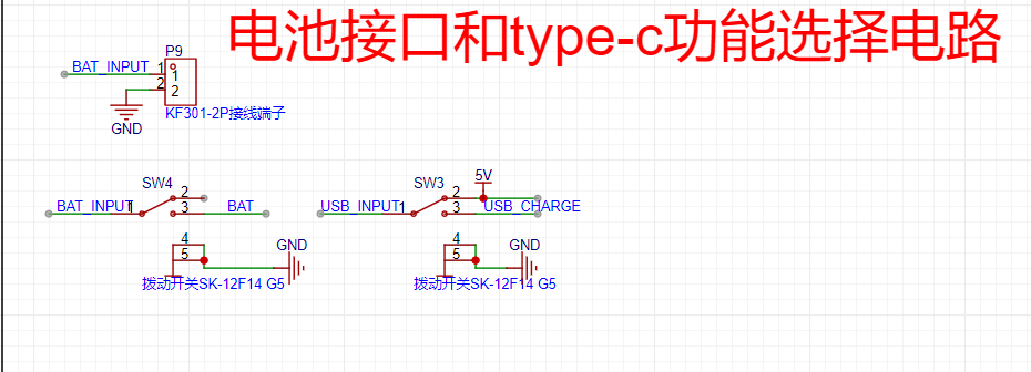 4. 2.5V Reference Circuit:
 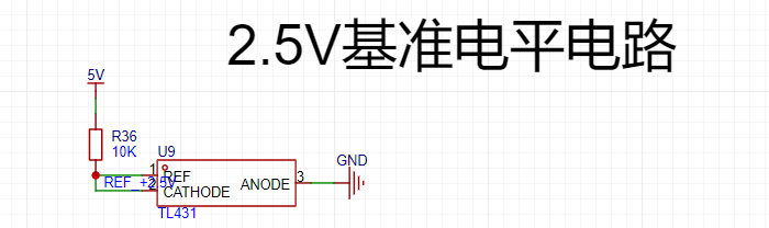 5. ADS1256 Sampling Circuit and Peripheral Circuit
 Images:

 The signal output circuit can output DC signals or directly output PWM signals. Essentially, it directly outputs signals from the microcontroller. The DC output level is achieved by adjusting the duty cycle of the PWM (the set signal frequency is 20kHz; for other frequencies, the DC calibration value needs to be modified), and then converting it into a "DC" signal through two stages of low-pass filtering.
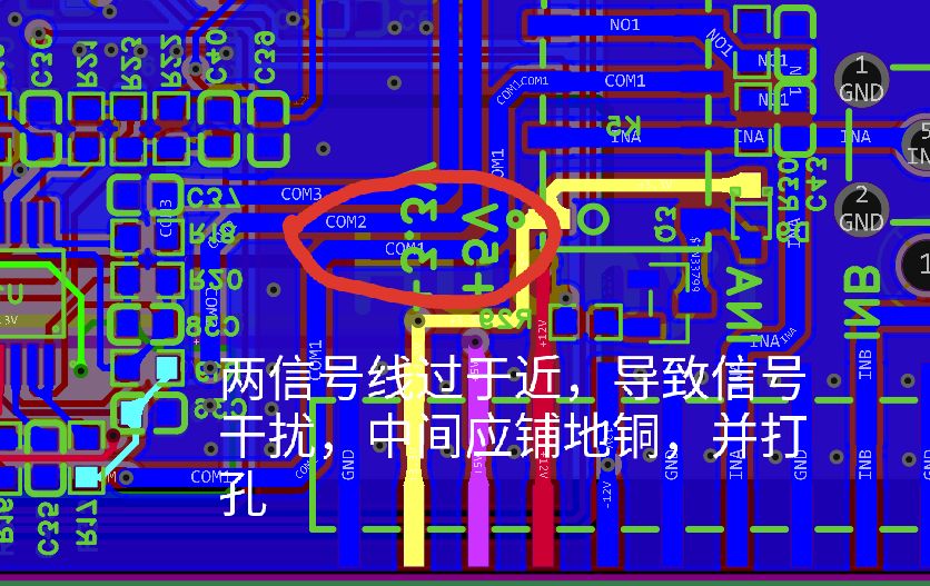
 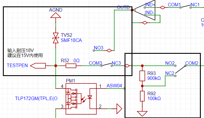 The diagram above (black box) shows the most basic signal input circuit. First, a bidirectional TVS diode protects the subsequent circuitry. Then, analog switch 3 (COM3 and NC3, NO3) allows selection between signal input and output modes (default output mode). Analog switch 2 allows selection of whether the input signal is attenuated. The analog front-end design references an oscilloscope, with an input impedance of 1MΩ. Like an oscilloscope, it allows selection of X1 and X10 ranges, with X10 selected by default. This design maximizes the safety of the subsequent circuitry, similar to how, when storing a multimeter with a separate power button, the range should be set to "AC voltage, maximum range."
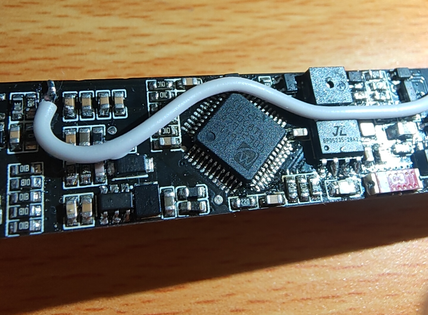
 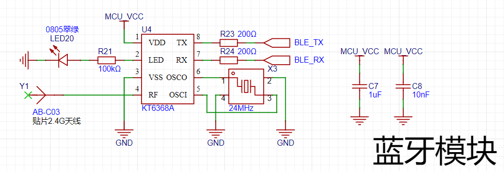 To facilitate connection between the test pen and a computer or mobile phone, I chose to use Bluetooth BLE technology for wireless data transmission.
  During PCB design, the area around the antenna should be kept clear to prevent interference from other signals and noise, which could lead to signal transmission bugs.
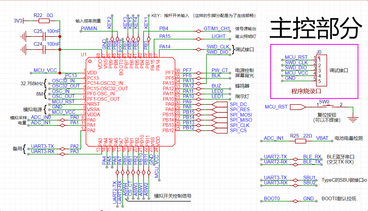
  This project uses a 0.96-inch TFT display screen with a resolution of 80*160, employing an ST7735 display driver chip. It is connected to the PCB via FPC soldering and communicates through an SPI interface. R18 is a backlight current-limiting resistor, which can control the display backlight via the BLK network controlled by the microcontroller, or it can be controlled by PWM dimming via a program.
  The user operation section of this project uses a five-way joystick switch, which can be understood as equivalent to five ordinary button switches. Programming it is also done as ordinary buttons.
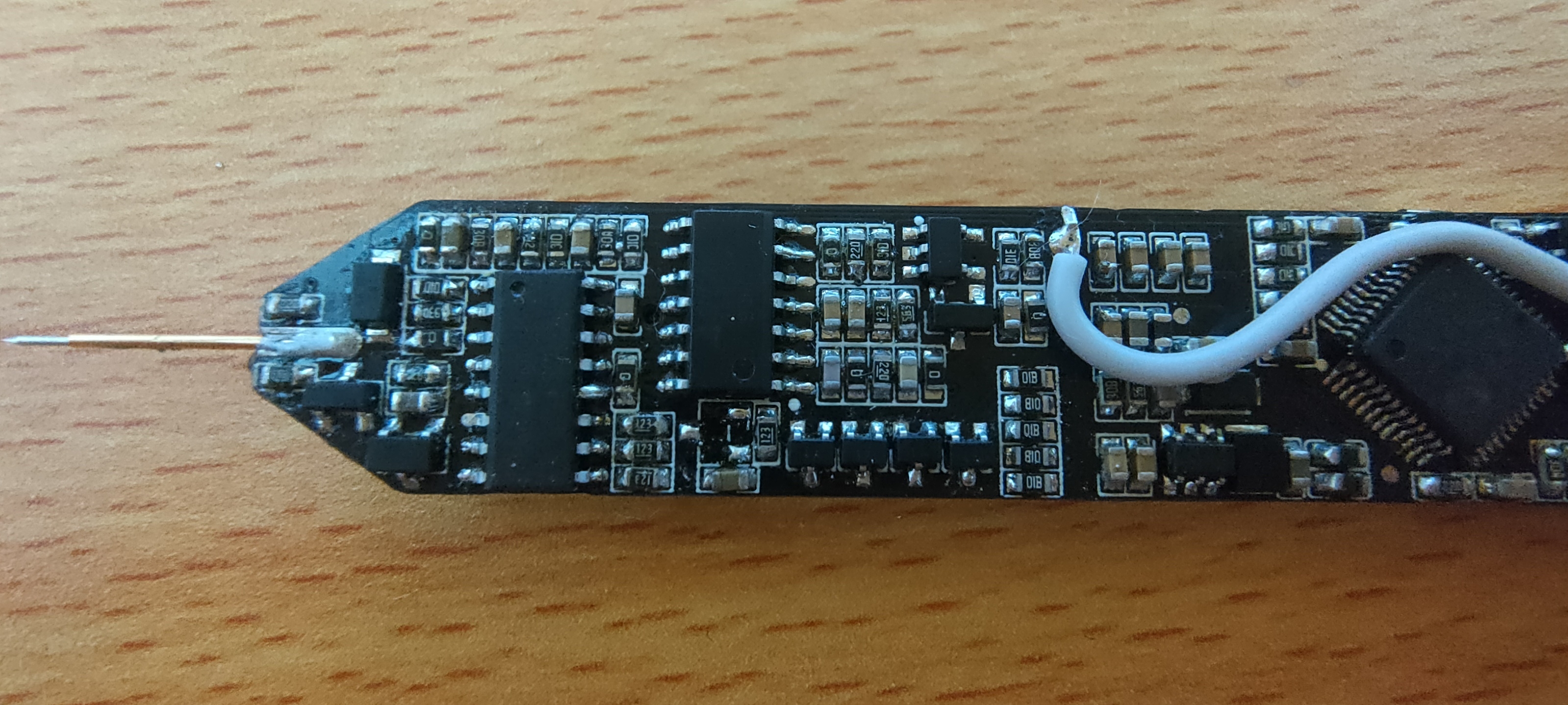
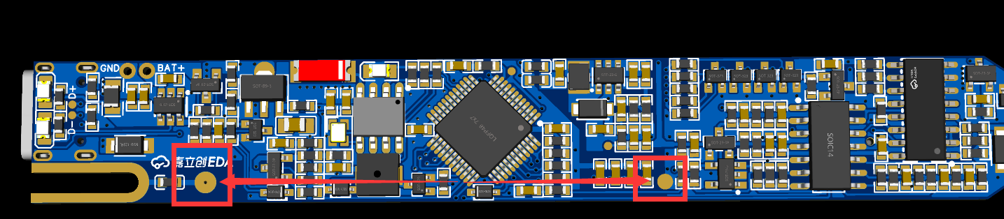
  Front) Note!!! After soldering, before use, be sure to connect the COM terminal and the analog ground terminal with a jumper wire!!! After downloading the program, calibration is mandatory for the first use! Otherwise, the measured data or output signal will be inaccurate! If used without calibration, reset the microcontroller using the reset button and then restart for calibration!

 3. The 40-pin display in the schematic cannot be driven (the screen has too many pixels, and the chip's memory is insufficient). An external display was designed using the SPI1 pin, so the 40-pin display can be removed from the reference design.
 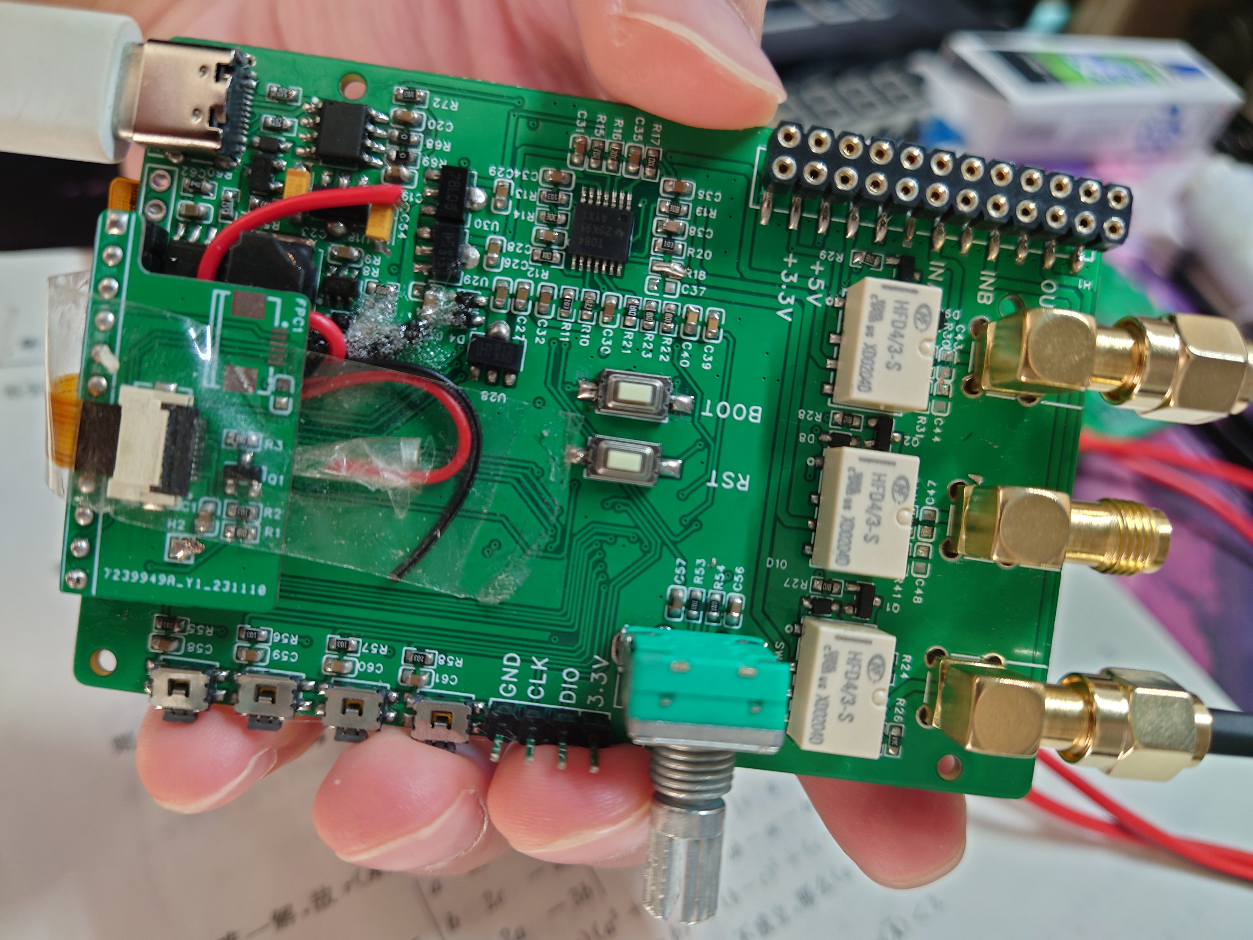 5. It can be connected to a battery, and an additional 8MB of FLASH memory was added, but this was not used at this time due to time constraints; it will be implemented much later.
All reference designs on this site are sourced from major semiconductor manufacturers or collected online for learning and research. The copyright belongs to the semiconductor manufacturer or the original author. If you believe that the reference design of this site infringes upon your relevant rights and interests, please send us a rights notice. As a neutral platform service provider, we will take measures to delete the relevant content in accordance with relevant laws after receiving the relevant notice from the rights holder. Please send relevant notifications to email: bbs_service@eeworld.com.cn.
It is your responsibility to test the circuit yourself and determine its suitability for you. EEWorld will not be liable for direct, indirect, special, incidental, consequential or punitive damages arising from any cause or anything connected to any reference design used.
Supported by EEWorld Datasheet
EEWorld
subscription
account

EEWorld
service
account

Automotive
development
community

Robot
development
community

About Us Customer Service Contact Information Datasheet Sitemap LatestNews


Room 1530, 15th Floor, Building B,
No.18 Zhongguancun Street,
Haidian District,
Beijing, Postal Code: 100190
China
Telephone: 008610 8235 0740
 京公网安备 11010802033920号

 AS91L1001E10L100CF


