
 INA, INB: The input terminals of the oscilloscope. The pocket instrument sends an analog signal to this point. Here, a 1MΩ input impedance is achieved through a series resistor voltage divider, generating two signals for selection: one is a direct input, and the other is attenuated to 1/20.
  gain: A selection switch that selects either the direct signal or the signal attenuated to 1/20 to enter the first-stage non-inverting amplifier. The non-inverting amplifier performs two functions: first, it amplifies the input signal at the non-inverting terminal by a factor of two; second, it shifts the amplified signal by 1.65V, calculated as Vo = 1.65 + 2*Vi. Therefore, the overall gain of the corresponding circuit is either 2 times or 1/10 times.
 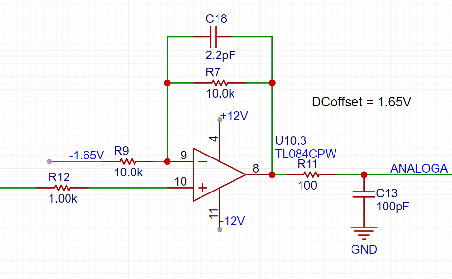 AnalogA and AnalogB: The analog signals, amplified and shifted by the inverting amplifier, are connected to the STM32H750 development board and enter the H750's ADC.
 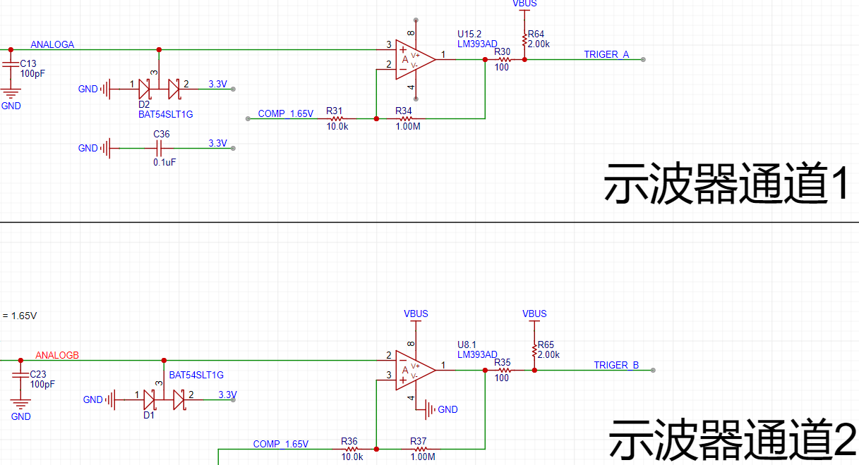 TrigerA and TrigerB: The square wave signal generated by AnalogA, AnalogB, and the DC reference level (generated by one of the H750's DACs) after passing through a comparator enters the STM32H750's timer for frequency measurement.
 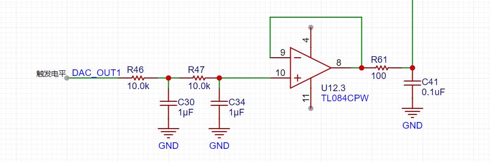 DAC_OUT2: The DC reference level is output through the STM32H750's internal DAC2 configuration.
 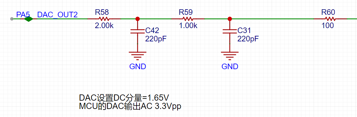 The STM32H750's DAC1 output has a waveform range of 0-3.3V.
 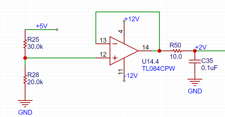 A resistor divider and buffer convert the 5V input to a low-impedance 2V output, which is then amplified by -5 times for shifting the output signal.
  The output amplifier performs two functions: first, it amplifies the non-inverting input by 6 times; second, it shifts the amplified signal by -10V before outputting it. The calculation formula is Vo = -10 + 6 * Vi.
 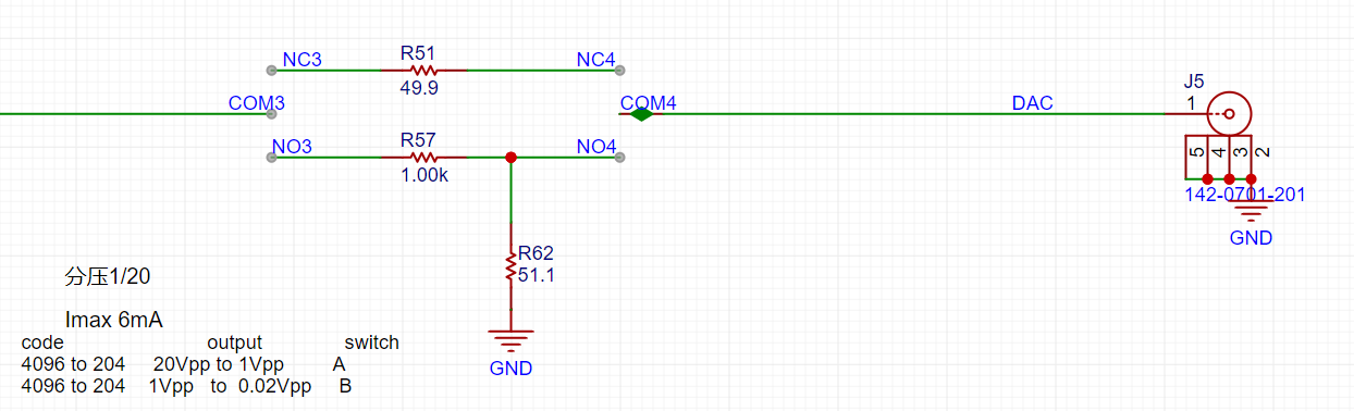 The voltage divider network is used to achieve good results when outputting small signals by utilizing analog circuit voltage division.
 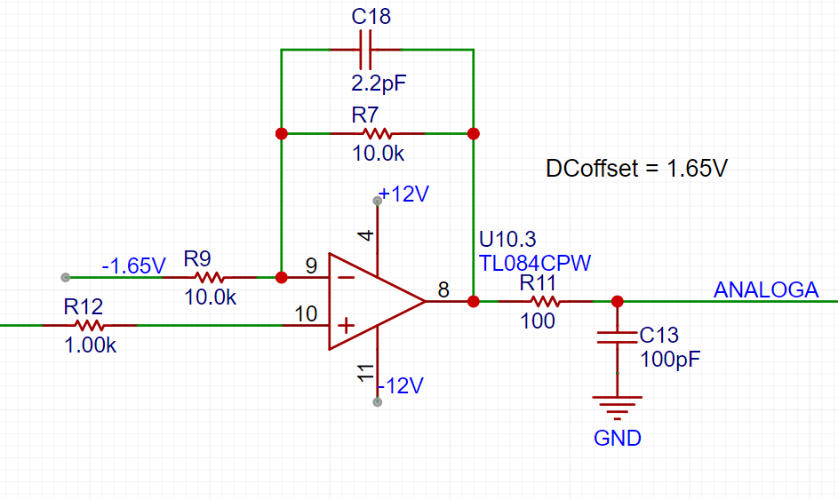 We can use the superposition theorem to analyze this circuit. First, when analyzing the contribution of the input signal INB to the output Vo, we ground the other voltage source in the circuit, -1.65V. This way, the input signal is divided to 1/20 after passing through R14 and R18, and then amplified by a factor of 2 by the non-inverting amplifier circuit. The overall gain of the input signal is 1/10. When analyzing the contribution of -1.65V to the output, we ground the input signal AIN, and the amplification factor of -1.65V is -1. Therefore, we obtain the output Vo = -1.65V * (-1) + AIN/10 = 1.65V + AIN/10.
  This circuit solves the problem of matching the ±15V input to the ADC's 0-3.3V input range. We also need to consider accurate sampling even with small input signals. For example, a 10mV signal will attenuate to 1mV after passing through this circuit. To maximize the signal-to-noise ratio of the input signal, we add a switching mode to the analog front-end. When acquiring small signals, the switch selects the direct input of INB to the non-inverting input of the op-amp, instead of selecting the attenuated signal from INB. This ensures the signal entering the ADC is as large as possible. Combined with a 16-bit ADC, this ensures accurate and reliable sampling results.
  As shown in the diagram, we add a signal switch (relay or manual switch) after the 1M ohm input voltage divider resistor to select whether INB enters the op-amp's non-inverting input directly or after being divided by 1/20. Both methods result in a 1M ohm input impedance for INB. When we need to acquire small signals, we can toggle the switch to use the direct input for more accurate measurement results.
  In the diagram above, the 0-3.3V signal output from the STM32H750's internal DAC is filtered by a low-pass filter and then input to the non-inverting input of the TL082, forming a non-inverting amplifier with a gain of 6. The amplified waveform is 0-19.8V. Then, utilizing the -5x amplification capability of the TL082's inverting amplifier section, the +2V obtained from the 5V voltage divider is amplified by -5x to obtain -10V. This -10V is then superimposed on the 0-19.8V signal output from the non-inverting amplifier to obtain an output of approximately ±10V. The calculation formula is: Vout = 6*Vin -10.
 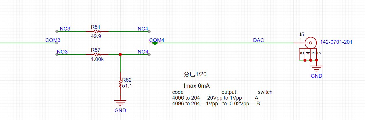 Similar to an ADC, to ensure the signal source output covers ±10mV to ±10V, while simultaneously balancing a large signal range and small signal accuracy, the DAC's resolution is a crucial factor. The H750's DAC is 12-bit, and its full-scale output (using all 4096 code values) is ±10V. When outputting small signals by reducing the DAC code value, to achieve a 7-bit voltage resolution (128 vertical points), the waveform must be attenuated by 128/4096 = 1/32. This translates to an output voltage range of ±10V/32 = ±0.3215V. For signals smaller than ±0.3125V, further reducing the code value results in insufficient DAC resolution and noticeable waveform steps. Therefore, we use analog voltage division. When outputting signals smaller than ±0.3125V, we use a switching resistor divider to attenuate the waveform by 1/20, ensuring sufficient voltage resolution for small signals. Simultaneously, the combination of R57 and R62 ensures a 50Ω output resistance at 1/20 attenuation, and R5 ensures a 50Ω output resistance at x1.
 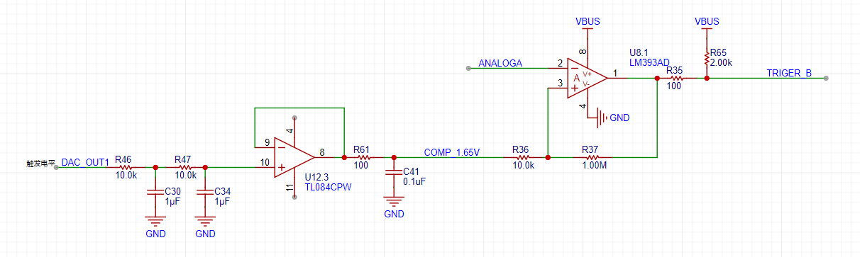 As shown in the diagram above, the H750 uses its internal DAC2 to output a 0-3.3V DC signal to compare with the waveform of channel 2 before it enters the ADC, converting the channel 2 waveform into a square wave. This allows the H750's timer function to use the square wave signal for interrupt handling and timer capture.

All reference designs on this site are sourced from major semiconductor manufacturers or collected online for learning and research. The copyright belongs to the semiconductor manufacturer or the original author. If you believe that the reference design of this site infringes upon your relevant rights and interests, please send us a rights notice. As a neutral platform service provider, we will take measures to delete the relevant content in accordance with relevant laws after receiving the relevant notice from the rights holder. Please send relevant notifications to email: bbs_service@eeworld.com.cn.
It is your responsibility to test the circuit yourself and determine its suitability for you. EEWorld will not be liable for direct, indirect, special, incidental, consequential or punitive damages arising from any cause or anything connected to any reference design used.
Supported by EEWorld Datasheet
EEWorld
subscription
account

EEWorld
service
account

Automotive
development
community

Robot
development
community

About Us Customer Service Contact Information Datasheet Sitemap LatestNews


Room 1530, 15th Floor, Building B,
No.18 Zhongguancun Street,
Haidian District,
Beijing, Postal Code: 100190
China
Telephone: 008610 8235 0740
 京公网安备 11010802033920号

 BC846A


