I. Overview
The AiPi-LRW-TH1 is a LoRaWAN sensor general-purpose board designed by the AiPi open-source team for the Ra-08H. It includes a general-purpose sensor interface supporting I2C+ADC+GPIO, a battery power interface, and a battery charging interface, and supports DIP switches to turn the power on and off.
The AiPi-LRW-TH1 can be applied in various scenarios to create smart agriculture, smart streetlights, and smart homes. After sensor data is collected by the Ra-08H, it is transmitted to the RG-02 gateway via the LoRaWAN protocol, and then uplinked to the LoRaWAN server. The data transmission distance is up to 4 kilometers. Low-power standby is achieved in standby mode when no data is being transmitted.
II. System Block Diagram
III. Sensor Interface
A GPIO interface supporting I2C+ADC is provided to accommodate sensors with various communication methods.
IV. Charging Circuit
The battery is charged using a Type-C interface and equipped with a charging indicator light.
V. Battery DIP Switch
The DIP switch can switch between battery power and power supply.
[For personal use] This ST-Link downloader was made using an STM32F103CBT6. It can support other download types, such as J-Link and DAP-Link, by changing the firmware.
I. Fabrication and Soldering
1. Schematic Diagram
: The ST-Link circuit on the Pandora IOT development board for the STM32L475VET6 from Zhengdian Atomic
was largely copied, but the reset pin for the main control chip was not brought out.
2. PCB Design:
The entire PCB was designed using LCSC EDA.
Firmware download was performed using the software 【STM32 ST-LINK Utility】 and 【STM32 CubeProgrammer】 ,
with an SWD download interface and one serial port brought out

. 3. Soldering:
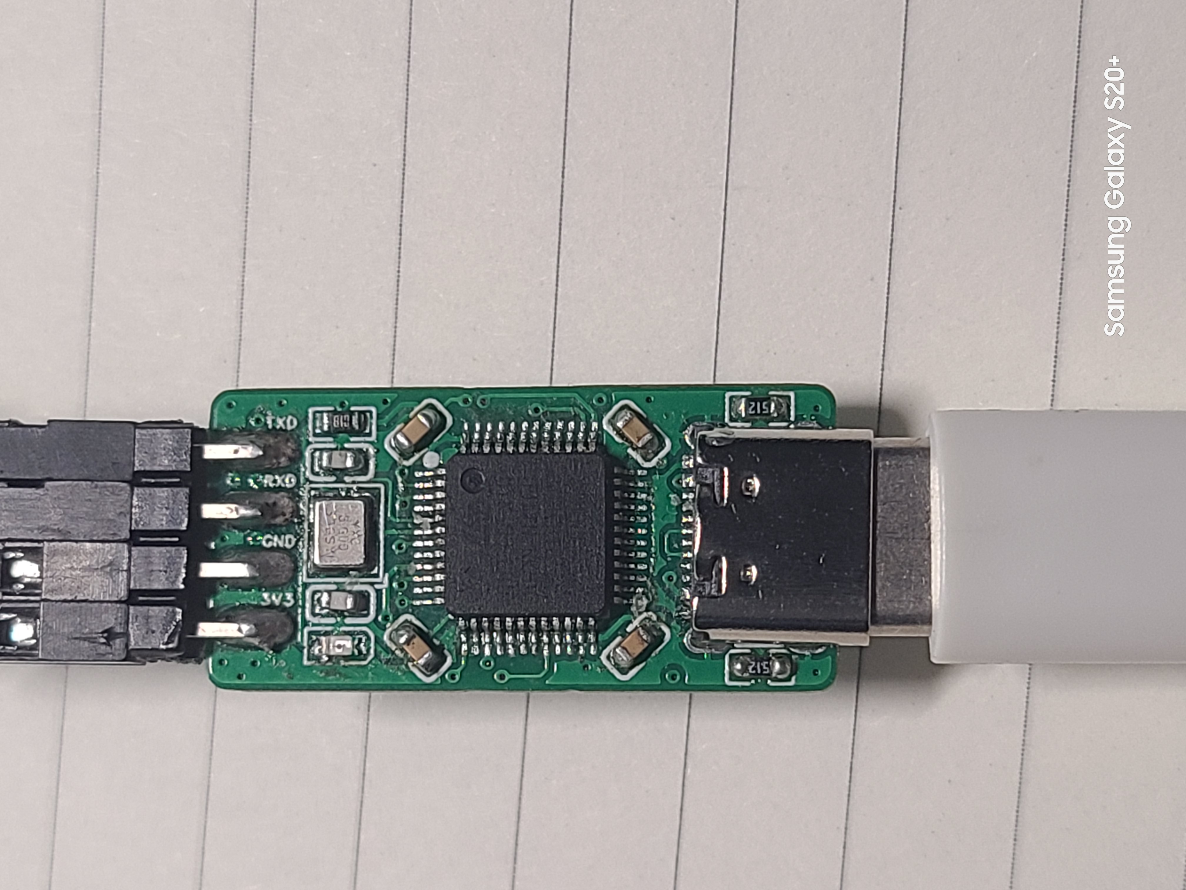
The onboard chip used is the 【STM32F103CBT6】. The chip integrates 128KB of Flash memory and 20KB of Static Random Access Memory (SRAM).
All resistors and capacitors are 0603 packages, which can be soldered using a hot plate, heating pad, or hot air gun.
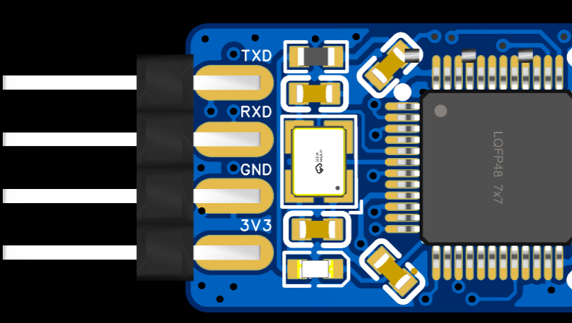
The onboard chip's download interface is displayed as a "test point" for easy firmware burning.
It uses a USB-C interface for convenient connection.
4. Finished Product Display

II. Firmware Burning and Testing
1. Original Firmware Burning
A ready-made ST-Link programmer is required. Then, use a soldering iron and DuPont wires to bring out the onboard chip's download port and use ST-Link to download the original firmware.
[Note] Since PA9 and PA10 are not brought out on the board, when purchasing a new chip, it can only be unlocked using software.
You can use an ST-Link programmer and the [STM32 ST-LINK Utility] software to unlock the chip (search online for specific steps).
Firmware can be downloaded using [STM32 ST-LINK Utility] or [STM32 CubeProgrammer] software (search online for specific download steps).
2. Firmware Upgrade After Download
Using TM32 Upgrade using the firmware upgrade tool included with CubeProgrammer. You can connect via USB-C cable to upgrade.
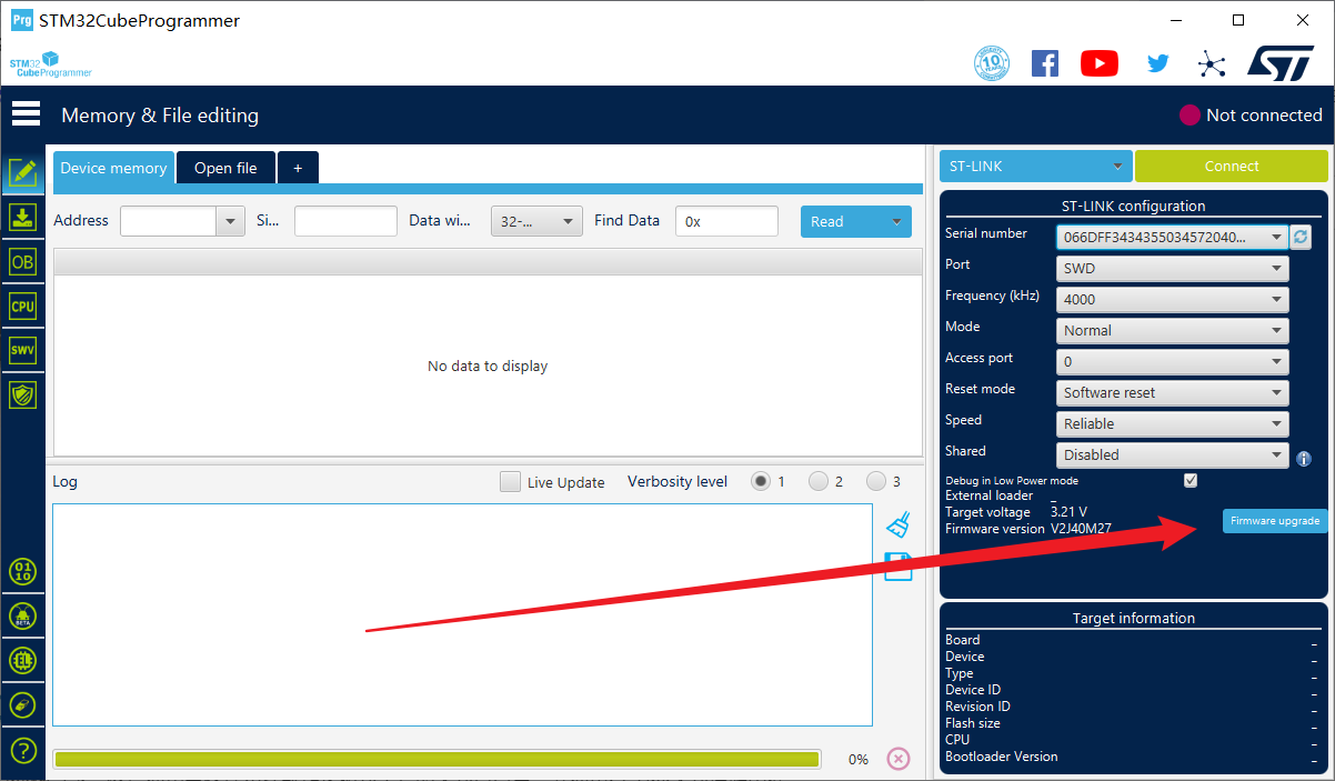

Click "Open in update mode," wait for the detection, then click "Upgrade" and wait for the download to complete.
3. To change the firmware
, you can use the ST-Link to J-Link converter to convert the firmware.

Follow the command prompts to complete the operation.
Only ST-Link and J-Link firmware were tested; DAP-Link firmware download was not tested.
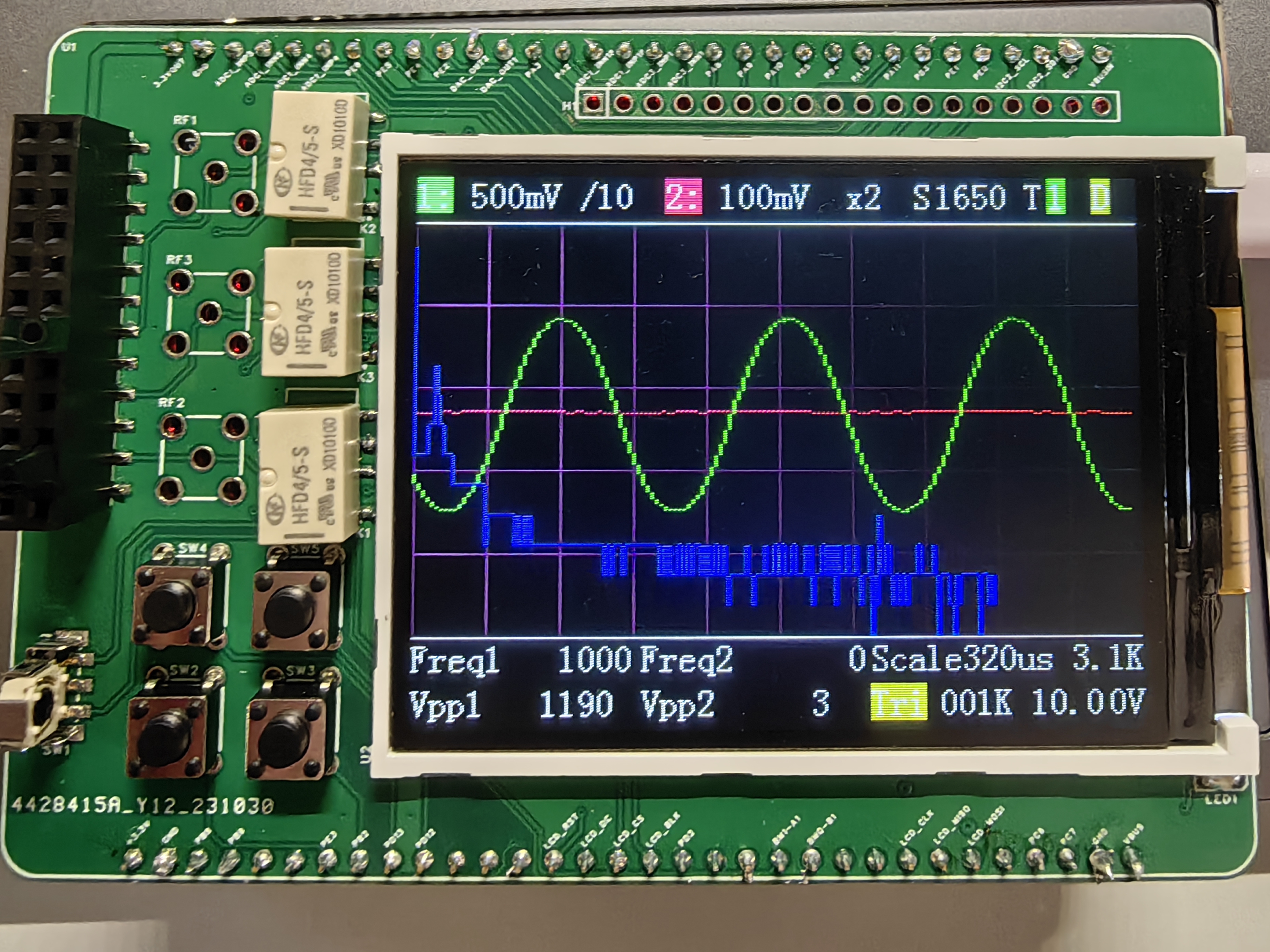
4. Testing showed that the board
supports drag-and-drop hex programming from a USB flash
drive. After testing, the board can be programmed and used normally on STM32F1 series chips, but not on STM32F4 series chips. The reason is under investigation and has not been determined.


The board can be recognized normally in both Keil and STM32 Cube Programmer software.


The virtual serial port can be recognized normally in the serial port debugging assistant, and it can be recognized normally under both different firmware versions. The image shows a loopback test.
III. The
issue of not being able to download to F4 will be further investigated.
The SW3556 features dual USB-C ports, supporting 7A (140W) fast charging output via both USB-C ports, and supports PPS/PD/QC/AFC/FCP/SCP/PE/SFCP/TFCP fast charging protocols.

 II. System Block Diagram
  III. Sensor Interface
  IV. Charging Circuit
 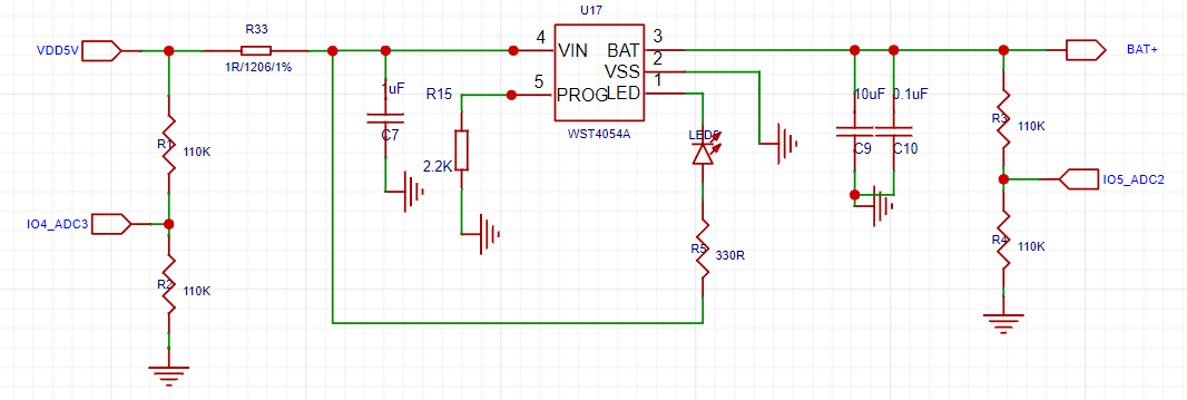 V. Battery DIP Switch

 Schematic
  PCB
PCB


 京公网安备 11010802033920号

 223886115279


