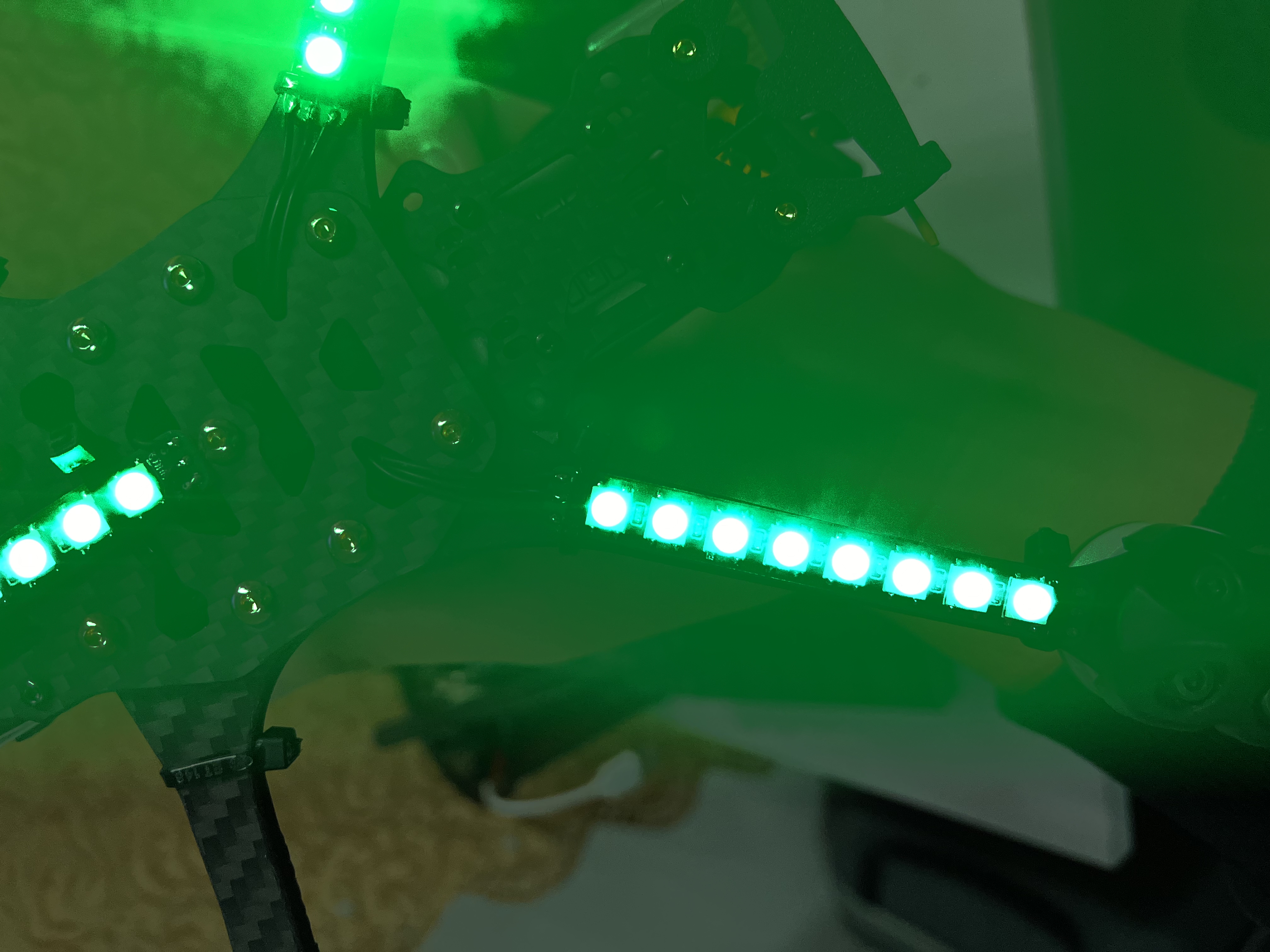
There are two lengths available: 55mm and 70mm. My rack is the Mark 5 DC version, and the 70mm length is perfect for its longer rear arm. The 55mm length should be just right for the standard version. You can adjust the number of LEDs according to your rack length. There's also a board for securing the XT60 power connector; it's installed at the rear of the rack for easier plugging and unplugging!
PDF_W2812 LED Strip for Racing Vehicles (RGB) - RGB LED Strip.zip
Altium_W2812 LED Strip for Racing Vehicles (RGB) - zip
PADS_W2812 LED Strip for Racing Machines (RGB) - zip
BOM_W2812 LED Strip for Racing Drones (RGB LED Strip) .xlsx
97187
IP5306 module
A minimalist, budget-friendly power bank solution based on IP5306
This is
a small gadget built using the IP5306_CK. It can directly charge a single 3.7V~4.2V lithium battery using 5V USB power, or output 5V 2A. Both input and output use USB-C ports (I recently got a bunch of USB-C ports from LCSC, which is ridiculously abundant).
Parameters
: Input: 5V 1.8A;
Charging current: 2.1A;
Charging cutoff voltage: 4.2V;
Output: 5V 2.4A.
Other functions: Lighting, power display (4-LED solution). A few notes : The output USB-C port
works fine when plugged into an external 5V USB power source; at least it didn't burn out. Connecting the output USB-C port to the input USB-C port via a C2C cable didn't burn out either, but it doesn't work properly (it's possible the lithium battery I'm using has too high internal resistance, acting as a protection mechanism). I used the DW03D solution instead of the DW01+ dual MMOS solution simply because I was lazy and didn't want too many chips.


PDF_IP5306 module.zip
Altium_IP5306 module.zip
PADS_IP5306 module.zip
BOM_IP5306 module.xlsx
97188
Dual-channel oscilloscope based on STM32H750VBT6 [Training Camp 2023.10]
This project originated from the JLCIC EDA Instrumentation Training Camp jointly organized by Hardwood Classroom and JLCIC. It is an oscilloscope expansion board used in conjunction with the H750 core board.
The I/O allocation in this project only applies to the Hardwood Classroom H750 core board. Please refer to the schematic diagram for specific allocation details.
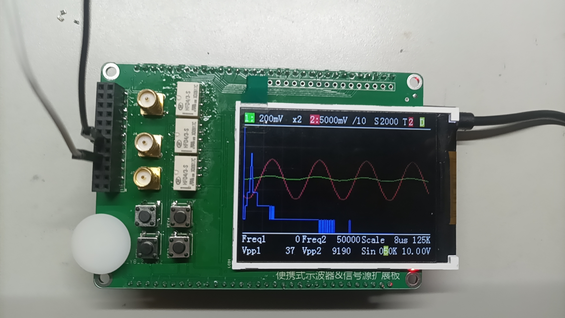
The finished product effect is shown in the image above.
VID_20231116_162651.mp4
VID_20231116_162835.mp4
PDF_Dual-channel Oscilloscope based on STM32H750VBT6 [Training Camp 2023.10].zip
Altium-based dual-channel oscilloscope using STM32H750VBT6 [Training Camp 2023.10].zip
PADS Dual-Channel Oscilloscope Based on STM32H750VBT6 [Training Camp 2023.10].zip
BOM_Dual-channel Oscilloscope based on STM32H750VBT6 [Training Camp 2023.10].xlsx
97189
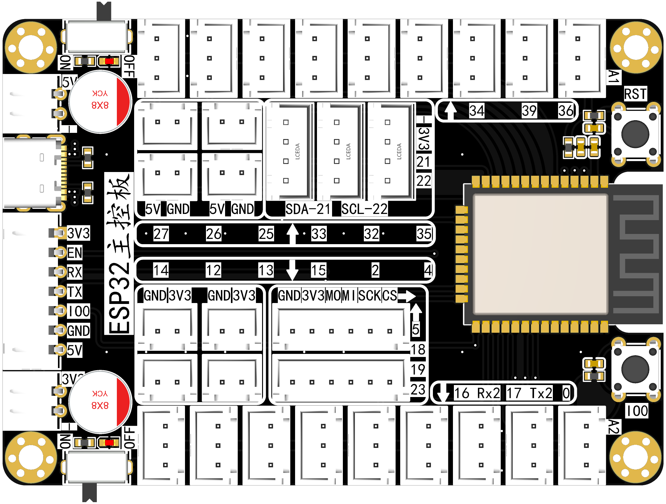
ESP32 expansion board
The ESP32 expansion board brings out all pins in a "VCC+GND+IO" configuration, a design suitable for learning and testing scenarios.
Version Description
Version Name: ESP32 Expansion Board V1.0
Release Date: 2023/11/15
I. Function Introduction
Project Introduction Video
This expansion board provides rich power and pin interfaces, making it ideal for learning and testing.
II. Screenshots

III. Functional Modules
1. Power Interface


Expansion Board Design Two power inputs: 5V and 3.3V. The 5V input uses a classic Type-C design and a 2-pin connector. The 3.3V input uses a 2-pin connector.
Four outputs are provided for both 5V and 3.3V to meet the needs of complex scenarios.
2. Switch Module

One switch is designed for both 5V and 3.3V, a standard design. Indicator lights are used to indicate the switch status.
3. Reset and Flashing Buttons

Reset and flashing buttons are provided for greater convenience. Flashing can be performed in conjunction with the ESP32 flashing sequence.
4. Flashing Interface
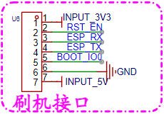
Directly connects to the ESP32 flashing board, reflecting a modular approach that reduces costs and increases efficiency.
5. Main Control Module

: The main control module uses the general-purpose ESP32-WROOM-32E, with built-in WIFI and Bluetooth modules. It features a dual-core MCU, ensuring stability and power.
6. IIC Interface
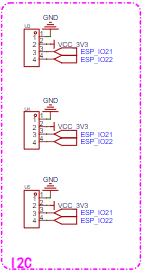
: Three IIC interfaces are reserved to meet simple application scenarios.
7. SPI Interface
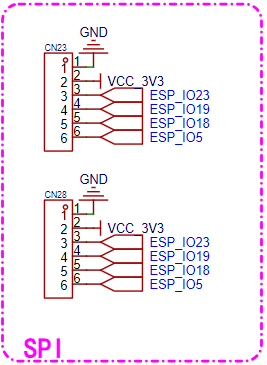
: Two SPI interfaces are reserved to meet simple application scenarios.
8. ADC Interface :


Sixteen ADC interfaces are brought out, which can also be used as ordinary GPIO.
9. UART Interface
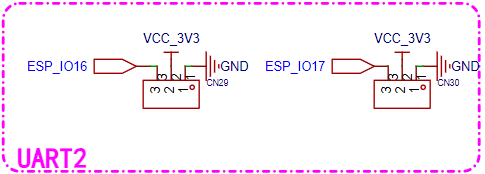
: Two UART interfaces are brought out, which can also be used as ordinary GPIO.
IV. Notes:
This project will be continuously improved and
updated. Update time: 15th or the last day of each month.
Materials can be obtained through:
UP: open01_T_Jupiter; duduvue;
QQ: 826793815.
Subsequent open-source projects and updates will be released on Bilibili, LCSC Open Source Platform, Github, and Gitee. Please follow for real-time updates!
PDF_ESP32 Expansion Board.zip
Altium_ESP32 Expansion Board.zip
PADS_ESP32 Expansion Board.zip
BOM_ESP32 Expansion Board.xlsx
97190
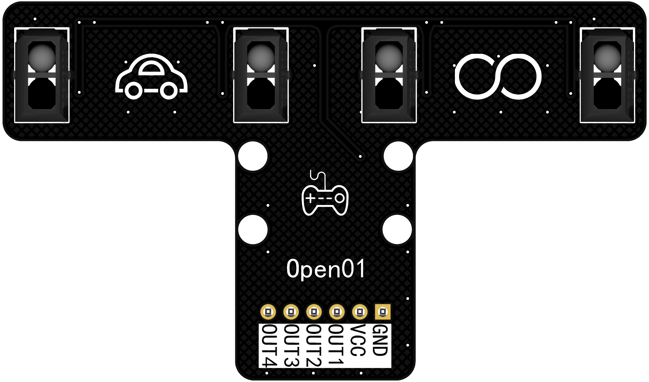
Infrared tracking
Four-way infrared tracking module
Version Description
Version Name: Four-Way Tracking Module V1.1, V1.2
Release Date: 2023/11/15
I. Function Introduction
Project Introduction Video
This module has four outputs, each equipped with an indicator light to indicate its status.
There are two versions: V1.1 with a 74HC14D chip, and V1.2 without this chip.
Elegant design. The design style is based on several excellent products found online. II. Renderings

III. Functional Modules
1. Power Indicator

This is a power indicator light; the brightness can be controlled by adjusting the resistance of R1.
2. Four-Way Infrared Tracking Module

The circuit logic of these four tracking modules is the same. The essence of infrared tracking is that different colors reflect infrared light to different degrees. This module uses the TCRT5000, which consists of an infrared emitter and an infrared receiver.
Its working principle is as follows, for example: When the infrared emitter encounters a black line, the reflected light is weak and cannot turn on the infrared receiver, so IN1 is high and the indicator light is off. When it encounters a white line, the reflected light is strong and can turn on the receiver, so IN1 is low and the indicator light is on. We can determine the color of the detected line based on the voltage level of the INx pin, thus achieving line tracking.
Note: Version V1.2 seems to be able to output analog signals, which can be analyzed in the description of the module's circuit diagram on Taobao. It's similar to the voltage divider form of a series photoresistor. This needs further testing and will be explained in the version description after testing.
3. Four Tracking Indicator Lights
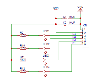
These four lights are indicator lights for the four-way tracking module, used to indicate the working status for easy observation and debugging.
4. Screw Holes

Four screw holes are reserved for easy installation.
IV. Remarks
This project will be continuously improved and updated.
Update time: 15th or the last day of each month.
How to obtain materials:
UP: open01_T_Jupiter; duduvue;
QQ: 826793815
Subsequent open source projects and updates will be released on Bilibili, LCSC Open Source Platform, Github, and Gitee. Please follow them for real-time updates!
PDF_Infrared Tracking.zip
Altium_Infrared Tracking.zip
PADS_Infrared Tracking.zip
BOM_Infrared Tracking.xlsx
97191
Photosensitive
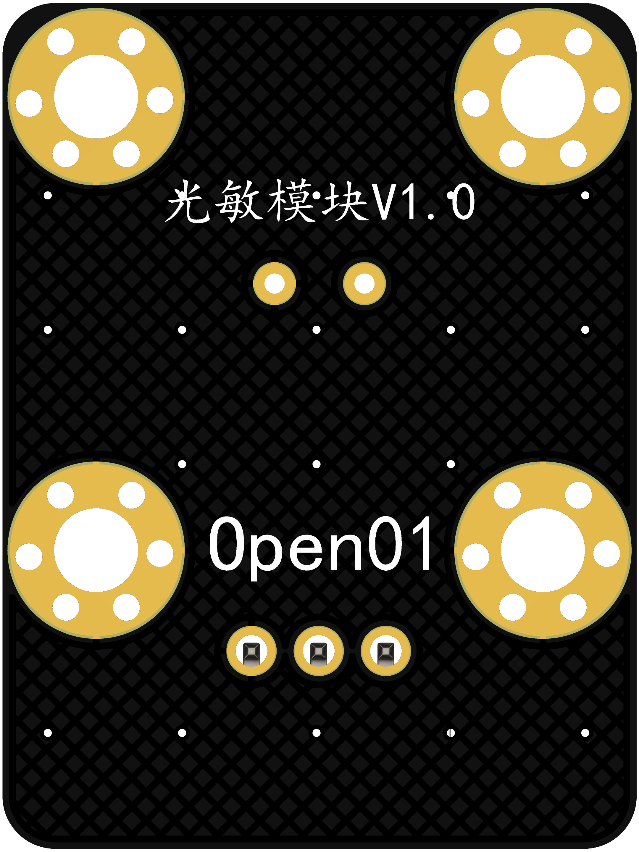
Photosensor module; includes 3D casing file;
Version Description
Version Name: Photosensitive Module V1.0
Release Date: 2023/11/15
I. Function Introduction
Project Introduction Video
This photosensitive module is an analog output
module with an elegant 3D shell
design. The design incorporates elements from several excellent online products. II. Renderings

III. Functional Modules
1. Power Indicator
This is a power indicator light; the brightness can be controlled by adjusting the resistance of R1.
2. Photosensitive Sensor

This photosensitive module is an analog output module. The photosensitive sensor is essentially a variable resistor affected by light intensity. Here, the light intensity is determined using the principle of voltage division. C1 is a filter capacitor to stabilize the signal.
3. Screw Holes
Four screw holes are provided for easy installation.
IV. Remarks
This project will be continuously improved and updated.
Update Time: 15th or the last day of each month.
Access Methods:
UP: open01_T_Jupiter; duduvue;
QQ: 826793815
Subsequent open-source projects and updates will be released on Bilibili, LCSC Open Source Platform, Github, and Gitee. Please follow for real-time updates!
moduleShell.stl
PDF_Photosensitive.zip
Altium_photosensitive.zip
PADS_photosensitive.zip
BOM_光感.xlsx
97192
electronic


 京公网安备 11010802033920号

 BTF-37WHCS-YW-S


