Recently, updating programs has been a hassle, requiring constant soldering. I decided to create a programming probe to simplify the programming process!
Below, I'll describe the drawing, materials, soldering, and manufacturing process:
1. Schematic: Haha, this board only has 5 wires, so a schematic isn't necessary, right?
2. PCB: On the left, I drew 5 pads, which I modified into 16*2mm oblong shapes with 1.38*15mm drilled holes.
The 5 wires in the middle connect to the terminals on the right; 1mm wire diameter is recommended.
The right side uses 2.54mm pitch angled terminals, which are common and easy to find.
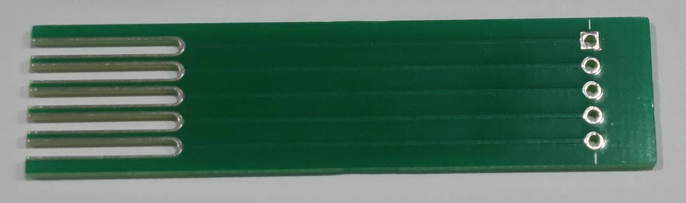

3. Probe: I used P100 probes, a common and inexpensive type.

4. Terminals: 2.54mm 5P terminals

. 5. Finished Product
: The assembly is simple; just add heat shrink tubing. It's still on its way; I'll add pictures when it arrives.

PDF_Burning Probe.zip
Altium_burning probe.zip
PADS_ProgrammingProbe.zip
97229
Remote control car
A control system for JJRC remote control cars based on ESP32.
Project Description:
This project is a control circuit developed for a JJRC remote control car.
Open Source License
: GPL 3.0.
Project Functionality:
This project is a control circuit developed for a JJRC remote control car and can be used with the remote control on my homepage. This control circuit uses the MX1919 for motor control. It can control one motor output. PWM is used to control two servo motors: one for steering and one for gear shifting. (The car in this project has high and low speeds). It also has image transmission capabilities.
Project Attributes:
This project is being publicly disclosed for the first time and is my original work. This project has not won any awards in other competitions.
Project Progress
: The PCB design is complete. This project has three PCBs.
The 3D model is complete.
The software program for remote control is complete.
The CNC bumper is complete.
Project Completion.
Design Principles :
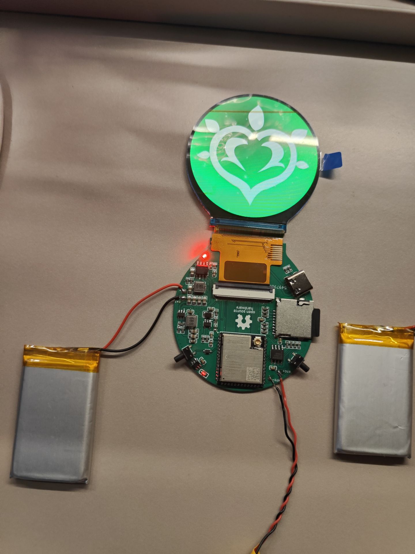
This project integrates the HeZoo Air780E4G module, enabling 4G remote control. This circuit uses the ESP32C3 as the lower-level machine. The NanoPIduo2 acts as the upper-level machine and image transmission, and is responsible for communication with external devices.
This project uses four 18650 batteries connected in two parallel and two series configurations as the power source. A power management module handles charging, discharging, and voltage transformation.
An ESP32C3 microcontroller controls an MX1919 motor via PWM signals on pins IO18 and IO19 to achieve forward and reverse speed regulation. Two servo motors are connected to pins IO6 and IO11 for steering and gear shifting. An ultrasonic ranging module is connected to pins IO7 and IO10 for obstacle avoidance, and an MPU6050 gyroscope is connected via IIC for automatic angle calibration. Pins IO2 and IO3 are used as an ADC to collect and monitor battery voltage. Serial port 1 of the ESP32C3 communicates with a NanoPiduo2 microcontroller for data uploading and command sending.
This control circuit has two control modes: 4G control and ESP-Now control, selectable via a switch. In 4G control, the NanoPiduo2 receives data and uploads video; in ESP-Now control, the NanoPiduo2 is turned off, and the AIR780E stops supplying power. Data is received and uploaded via ESP32C3.
Software Description:
Currently, in 4G mode, there is no server available, so there is no suitable solution for the program.
The ESP-Now program
is shown in the attached physical demonstration:
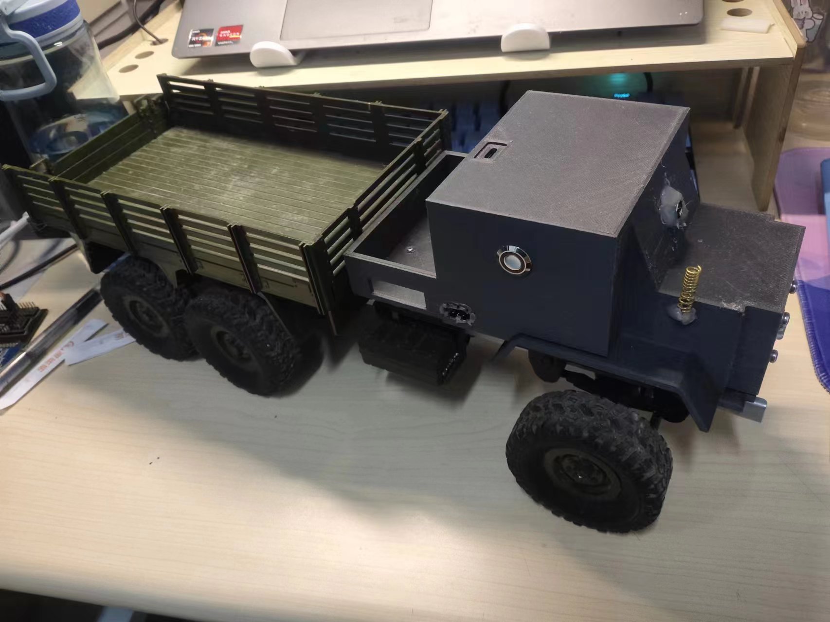
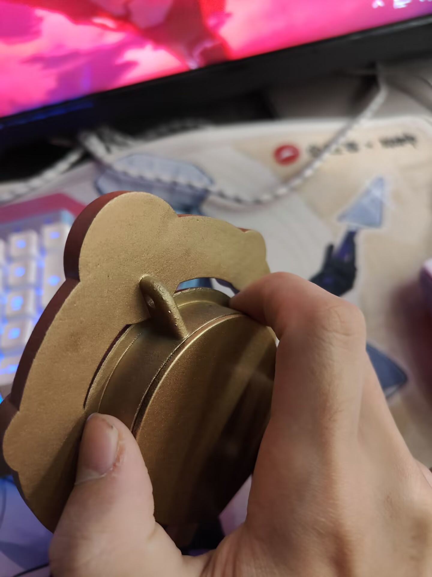
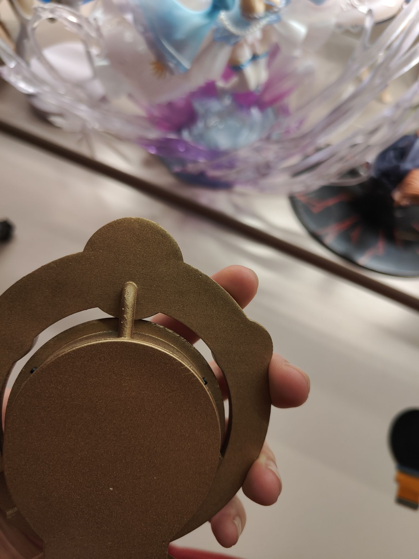
Figure 1 shows the vehicle's exterior;

Figure 2 shows the vehicle's internal structure; Figure 3 shows
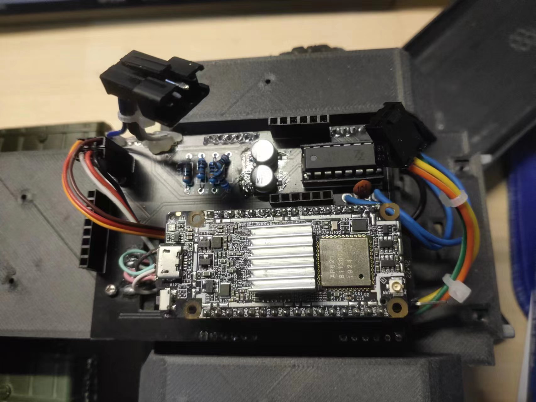
the upper part of the control circuit;
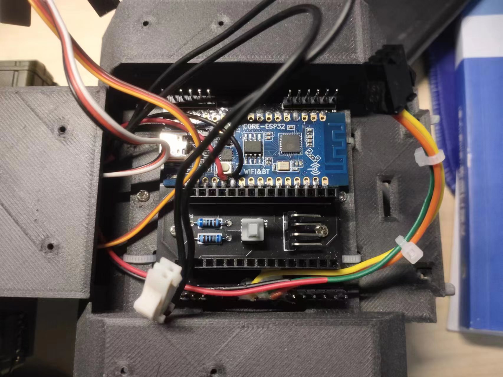
Figure 4 shows the lower part of the control circuit .
Design Notes:
Due to my lack of experience, there are many shortcomings in the hardware design and circuitry, such as an unsuitable lithium battery protection chip selection leading to easy overcurrent protection, and inaccurate 3D model openings. Although it is usable, this project is generally considered a failure. Therefore, I hope this project will primarily provide a framework for improvement, and I will continue to refine it. Suggestions are welcome.
jjrc.ino
PDF_Remote Control Car.zip
Altium_Remote Control Car.zip
PADS_Remote Control Car.zip
BOM_Remote Control Car.xlsx
97231
PCAN_V1.4
CANFD tool
Support PCANFD firmware
PDF_PCAN_V1.4.zip
Altium_PCAN_V1.4.zip
PADS_PCAN_V1.4.zip
BOM_PCAN_V1.4.xlsx
97232
Based on AirF103, HeZhou Daplink
Daplink based on HeZoo Air32F103
To resolve the lack of 5V power supply in the official DAP from Heze Technology, the pins are adapted to the development board from Fanke Technology, allowing for direct plug-in connection (requiring disconnecting the 0-ohm resistor connected to the 3.3V pin on the back). Bring out boot0, use ISP download, TX and RX correspond to PA9 and PA10 on the back
, consistent with the STM32 ISP download method. After using an ISP download tool (FlyMcu, etc.) to burn the daplink_v2.hex firmware, connect to the computer via Type-C to check if it is recognized correctly. Disconnect, short-circuit RST and GND, then connect to the computer. A pop-up window will appear; disconnect RST and GND, select Firmware 1 or Firmware 2 and drag and drop to burn. (Firmware 1 is the official V2 version upgrade firmware; Firmware 2 removes the USB flash drive function and network pop-up).
For detailed usage and upgrade methods, please refer to the Heze official website DAPLink User Manual - LuatOS document.
daplink_v2.hex
Firmware 1.hex
Firmware 2.hex
PDF_Based on AirF103, HeZhou Daplink.zip
Altium_based on airf103 and Daplink.zip
PADS_Based on airf103 and Daplink.zip
BOM_Based on Airf103 and Daplink.xlsx
97234
DIY ESP32 Development Board (using ESP-32S as an example)
This project aims to create an ESP32 development board, including an ESP32 module and a CH340C chip. The goal is to implement the basic functions of an ESP32 development board and include automatic download functionality.
I used a Type-C interface because I dislike the hassle of having both microUSB and Type-C data cables, although soldering is a bit more difficult. I'm also new to this platform, and I'm having trouble displaying images, so I'll just describe it in words for now. The automatic download function is copied from someone else; I haven't thought about the logic in detail, but it works for now. The power supply uses an AMS1117-3.3 step-down converter. I randomly copied a version from another board, but later realized the package size was too small; you need to pay attention to the package size. Then there are a few capacitors. I'm not entirely sure whether larger or smaller capacitors should be closer to the chip, but it shouldn't matter much on this board. Then there's the CH340. As far as I know, the CH340C has two connection methods, and mine is one of them. The pull-high pins 9-12 are copied from someone else; I'm not sure if it's correct, but it works. Also, if you're going to use this board, remember to use the CH340C. I originally planned to use this board for my graduation project, but I used a CH340G I bought a long time ago, and it just wouldn't connect. Later, I redesigned the board and moved the components over, but it still didn't work. The schematic looked perfect to me, so the development board for my graduation project wasn't my own design. Later, I tried to redesign it again, using the same components, but it still wouldn't connect. After a long time, I realized I was using the wrong chip, and I was furious. Oh, by the way, R9 and R10 are in the schematic, but I deleted them from the PCB layout because I saw different connection methods and wanted to try pulling them high or low. It worked without them, so I just left them floating. Actually, this board is almost entirely designed around the CH340. Once the CH340 works, the board is fine. I'm going to design an adapter board to connect to peripherals like screen ranging later :) JLCPCB is getting YYDS for free.
PDF_DIY_ESP32 Development Board (using ESP-32S as an example).zip
Altium_DIY_ESP32 Development Board (using ESP-32S as an example).zip
PADS_DIY_ESP32 Development Board (using ESP-32S as an example).zip
BOM_DIY_ESP32 Development Board (using ESP-32S as an example).xlsx
97235
STC8H8K64U-DIP40 Development Board
I bought this chip but found that the pin numbers on the boards on the market didn't match, so I drew one myself. I only have surface mount components at home, so most of my components are surface mount.
The STC8H8K64U-DIP40 chip
is mostly a surface-mount component.
Keil simulation
reference circuits are available
at: 1. https://oshwhub.com/xiezhaoyan/stc8h8k64u-dan-pian-ji-zui-xiao-xi-tong-100-zhi-cha-yuan-jian
2. https://www.stcmicro.com/datasheet/STC8H-cn.pdf
Press and hold the P3.2 button to power on and enter download mode. Serial port download is also possible.
STC8H_Datasheet.pdf
PDF_STC8H8K64U-DIP40 development board.zip
Altium_STC8H8K64U-DIP40 development board.zip
PADS_STC8H8K64U-DIP40 development board.zip
BOM_STC8H8K64U-DIP40 Development Board.xlsx
97236
God's Eye Plus minor update
This project is a modified version of the Little Scumbag God's Eye Plus project (https://oshwhub.com/myzhazha/shen-zhi-yan-plus), with some modifications made to fit its own firmware.
This project was initiated at the request of a group member. It's a modification of the "Little Scumbag God's Eye Plus" project (https://oshwhub.com/myzhazha/shen-zhi-yan-plus).
The main changes are as follows:
1. The original USB used CH340 for programming, which prevented the use of the USB data transfer function in my firmware. This version uses a USB CDC port for programming and data transfer.
2. The original button 2 was blocked by the USB port and was difficult to press. It has been changed to a stopwatch-style button (top left and top right) that is more ergonomic.
3. The original version could not be powered on when plugged in and required a battery. This version allows it to power on directly when plugged in.
4. The original DC-DC chip is far too small, making it difficult for older people (like myself) to solder. This version modifies the charging and power supply scheme to IP5306_CK + MP1471, making it easier to solder.
5. Due to insufficient GPIO, the original used a 3-IO DS1302RTC clock chip. This version uses an I2C DS3231 clock chip (more accurate, more expensive).
Both versions have synchronized firmware updates and no functional differences (this version adds USB data transfer, allowing direct data copying without removing the card). For all files, directories, and production methods, please refer to the original instructions (Zha Yi's explanation is incredibly detailed).
Related materials and firmware can also be downloaded from my cloud drive: https://pan.baidu.com/s/19-CHRh_MAejMqFVaL9os6Q?pwd=e8y5.
All new features and firmware will be posted there.
Note that you need to drill holes in the case yourself according to the new model. For IP5306, you need to buy the version with CK (available on Youxin).
This has been verified and successfully produced by a certain Deli Sha.

PDF_God's Eye Plus Minor Modification.zip
Altium_God's Eye Plus minor update.zip
PADS_God's Eye Plus minor update.zip
BOM_God's Eye Plus Minor Modification.xlsx
97237
esp32_cam replica circuit
The circuit of the Anxinke ESP32-CAM has been copied to facilitate secondary design.
Circuit Source:
ESP32-CAM Camera Development Board | Ai-Thinker Technology (ai-thinker.com)
Circuit Modifications:
1. The download port has been modified with a download mode toggle switch. When switched to download mode (GPIO00 connected to GND), the serial port can download programs. Referring to the previous cold-start-free download circuit, batch program burning can be achieved.
2. The ESP32-CAM DEMO program can be used to implement webcam monitoring in a browser. Other functions can be developed as needed.
Discussion:
1. My usage only requires capturing images of a few tens of kilobytes, so the prototype circuit can eliminate the TF card and PSRAM, and even eliminate the ESP32-WROOM-32-N4, directly using the ESP32-S2 microcontroller design.
2. The ESP32-WROOM-32U module can be used to replace the ESP32-WROOM-32-N4, with the same package and pinout.
PDF_esp32_cam replica circuit.zip
Altium_esp32_cam replica circuit.zip
PADS_esp32_cam replica circuit.zip
BOM_esp32_cam replica circuit.xlsx
97238
Handheld detector (based on Liangshan School)
This project is based on the Environmental Monitoring Extension Board project, a project that was shelved due to procrastination (x)
Project Introduction:
This project is based on an environmental monitoring expansion board project, with slight modifications.
Expected Functionality
: Basic Functions:
Temperature and humidity sensor: for detecting temperature and humidity data;
Barometric pressure sensor: for detecting atmospheric pressure data;
Harmful gas sensor: for detecting harmful gases and other data;
Screen: for real-time display of collected data;
Wireless communication: for sending data to receiving devices.
Desired Additional Functionality (Under Development):
Compass,
leveling instrument, distance measuring instrument , illuminance detection
circuit design. For basic circuit design and functional circuits, please refer to the official case study. Other functional circuits of the environmental monitoring expansion board will be explained after testing (the remaining modules are mostly I2C communication, and their circuit reference value is not significant). Currently, the project runs the official code correctly. I am currently learning LVGL interface development and debugging the remaining modules for physical verification.
Physical verification.mp4
Official complete test cases.zip
Module Status Test.zip
PDF_Handheld Detector (Based on Liangshan School).zip
Altium_Handheld Detector (Based on Liangshan School).zip
PADS_Handheld Detector (Based on Liangshan School).zip
BOM_Handheld Inspection Device (Based on Liangshan School).xlsx
97239
PCM2706C+ES9023P-USBDAC
USB Type-C input, PCM2706/PCM2707 output I2S, ES9023P as DAC, sound quality meets the needs of listening to music during work.
This is a modified version of the aesthetically pleasing and functional Es9023-USBDAC from JLCPCB's EDA open-source hardware platform (oshwhub.com).
It was changed from Micro USB to Type-C USB, with minor modifications to inductors and other components. The ground plane copper pour was also slightly altered.
The total size is 12*82mm
. The cost on Taobao is approximately 20 RMB (excluding common components like resistors and capacitors).
I recommend using the PCM2707C, as it's cheaper than the PCM2706C.
The structural components are naturally unusable; it's wrapped in heat-shrink tubing mainly because the board is small and easy to lose (though you might eventually lose it).

PDF_PCM2706C+ES9023P-USBDAC.zip
Altium_PCM2706C+ES9023P-USBDAC.zip
PADS_PCM2706C+ES9023P-USBDAC.zip
BOM_PCM2706C+ES9023P-USBDAC.xlsx
97242
electronic


 京公网安备 11010802033920号

 177-714-1-15GP0J1-24MDN


