Project Introduction:
A microcontroller with USB, BLE 5.3, and 40 I/O ports, priced at only 3 yuan. Except for the slightly limited SRAM, it's quite attractive.
This project has been board-made and verified to be usable.
This project is based on the schematic of the Qinheng official EVT development board, with some simple adjustments. An I2C interface is provided for connecting a temperature and humidity sensor. The
temperature sensor used is a very inexpensive AHT20/21 temperature and humidity sensor. Other than that, the silkscreen printing was stylized, and one of my favorite characters, Sugar Sauce, was added. You can modify or delete it if you don't like it. A white board is recommended for better backlighting.
The antenna used is the official antenna, and a simple 50Ω impedance matching was done. The effect is shown in the picture for fun.
A 1.2mm thick board is required.
Physical demonstration:
front

and back,
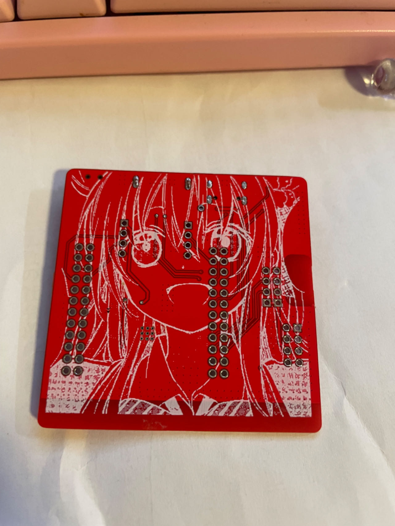
white rendering effect.


Chip
Introduction :
The CH583 is a 32-bit RISC microcontroller with integrated BLE wireless communication. The chip integrates a rich array of peripheral resources, including a 2Mbps Bluetooth Low Energy (BLE) communication module, two full-speed USB host and device controllers and transceivers, two SPIs, four serial ports, an ADC, a touch button detection module, and an RTC. The CH582 lacks one SPI1 compared to the CH583. The host and other components are identical.
Application block diagram.

Product features:
32-bit RISC processor (Qingke V4A)
, supports RV32IMAC instruction set, supports hardware multiplication and division;
32KB SRAM, 512KB Flash, supports ICP, ISP, and IAP, supports OTA wireless upgrades
; built-in 2.4GHz RF transceiver and baseband and link control, supports BLE 5.3;
supports 2Mbps, 1Mbps, 500Kbps, and 125Kbps
receiver sensitivity -98dBm, programmable +7dBm transmit power ;
provides protocol stack and application layer API;
built-in temperature sensor;
built-in RTC, supports both timed and trigger modes;
provides two USB 2.0 full-speed Host/Device ports
; provides 14-channel touch buttons;
provides a 14-channel 12-bit ADC;
provides four UARTs, two SPIs, 12 PWM channels, and one IIC channel.
It features 40 GPIOs, 4 of which support 5V signal input and
a minimum power supply voltage of 1.7V. It also includes
a built-in AES-128 encryption/decryption unit. The chip's unique ID
is QFN48. For more information, please refer to the development guide on
the Qinheng official website . This article shares some experience based on my recent research on this chip. Qinheng chips can use the officially recommended IDE, MounRiver Studio, but unfortunately, it doesn't support Mac OS, so I can't use it. You can use VS Code with PlatformIO for development, supporting the Arduino framework (arduino-wch58x), or you can write your own CMake build scripts. For example, see https://github.com/mo10/ch58x-cmake-template, and then use OpenOCD for simulation and debugging. However, it's important to note that although the two-wire simulation interface looks similar to the ARM Cortex-M series, common debuggers such as JLINK, STLINK, and DAP-LINK are incompatible. You need to purchase the dedicated debugger WCH-Link. There are several types of WCH-Link available, so be careful when choosing. WCH-LinkE is recommended here. For more information on debuggers, please refer to the official website: https://www.wch.cn/products/WCH-Link.html. Furthermore, manually opening debug mode using the ISP tool every time you debug is inconvenient. Downloading programs can be done via USB or serial port; USB download is more convenient. The download tool is wchISPtool, which can be downloaded from the attachments or the official website. However, WCHISPTool is only available for Windows. For Linux or Mac OS, you can use a third-party tool: https://github.com/ch32-rs/wchisp. If you don't want to compile, you can directly download the corresponding system package from the project's release and run it. Regarding hardware debugging :** Some shops on Taobao sell fake chips that cannot be recognized by the ISP tool after soldering, and the official chips are not available for sale. To enable the ISP tool to recognize the chip when using USB programming, press and hold the "Download" button on the evaluation board, or short PB22 to GND while powering on the board. If it's the first time you receive the chip, the codeflash will be empty, and the ISP tool will recognize it without pressing the "Download" button. If you encounter USB programming errors, first check if the programming environment is normal: ① Check the soldering: ensure the GND pin of the chip has been properly soldered, and check for cold solder joints or missing solder joints on PB10 and PB11. ② Check the power supply: ensure the voltage on the VINTA pin of the 57x and 58x chips is within the range of 1.05±0.015V, and the VINTA of the 208 is around 1.2V. ③ Check if the 32MHz crystal oscillator is oscillating; a normal 32MHz crystal oscillator is necessary for the normal operation of all chip modules. ④ Check the USB cable: test the cable to see if it can successfully program the evaluation board or other known-to-be-normal boards. Some cables do not have D+ and D- signal lines; do not use such cables. ⑤ Check if PB22 is brought out as the download configuration pin; PB22 needs to be grounded upon power-up to enter the bootloader. ⑥ Check if multiple ISP tools are open; the chip may have been recognized in other windows. ⑦ Check if the download configuration pin has been changed to PB11. If you accidentally modify PB11, you need to connect PB11 to v33. After powering on, quickly disconnect PB11 from v33 to re-enter the bootloader and modify the download configuration pin. If you frequently need to switch between PB22 and PB11, or if the project itself uses the USB1 interface as a download port and requires PB11 as the download configuration pin, you can connect a pull-up resistor of at least 1.5K (e.g., 10K) and a button to v33. Pressing the button will connect this pull-up resistor to PB11. This way, the built-in 1.5K pull-down resistor of the USB interface is relatively strong and will not affect USB communication after power-on boot recognition, saving one GPIO on PB22. If the burning environment is fine, observe whether the computer displays a prompt when the board is connected to the computer via USB. ① If the computer displays a prompt indicating excessive current: check if the GND and VCC pins of the USB port on the board are reversed, if there are short circuits on the board, or if any components are damaged.
② If the computer displays a message indicating that the chip cannot be recognized: Check if PB10 and PB11 are connected incorrectly, if there is interference or a short circuit to other pins, and if unnecessary strong pull-up/pull-down resistors or capacitors have been added. For USB programming issues, test with both pins floating first. If there are special requirements, add circuitry to check for compatibility. If the project uses USB1, be sure to disconnect other hosts/devices from the USB1 port.
③ If the computer does not display a message: Check if PB10 and PB11 are short-circuited. Cables are usually male at both ends. Connect the USB female port on the board to the A female port and check if the D+ and D- lines on the A female port are short-circuited.
⚠️ Note that some shops on Taobao sell counterfeit chips; you need to verify this yourself. If you are interested, you can apply for a development board from the official website; approval depends on luck.
If you want to make a product, you can buy one with high sales volume and many reviews on Taobao.
References and thanks to:
Troubleshooting USB programming for Qinheng Bluetooth series chips: https://www.cnblogs.com/JayWellsBlog/p/16934725.html;
wchisp: https://github.com/ch32-rs/wchisp;
arduino-wch58x: https://github.com/ElectronicCats/arduino-wch58x
; ch58x-cmake-template: https://github.com/mo10/ch58x-cmake-template;
CH573, CH579, and CH582 programming instructions: https://www.cnblogs.com/risc5-ble/p/16865626.html


 京公网安备 11010802033920号

 Z4KE200


