 Other components won't be explained in detail for now because I don't think anyone would actually replicate this XD. The video content provides a basic explanation of the functions. For this experiment, I suggest freely modifying the values, packages, and models of many electronic components to deepen your understanding. This depends on the components you have on hand. These are the components I have, so I haven't checked if the BOM selection is completely reasonable, but it's generally correct. (Complete demonstration video, digital circuit project collection)
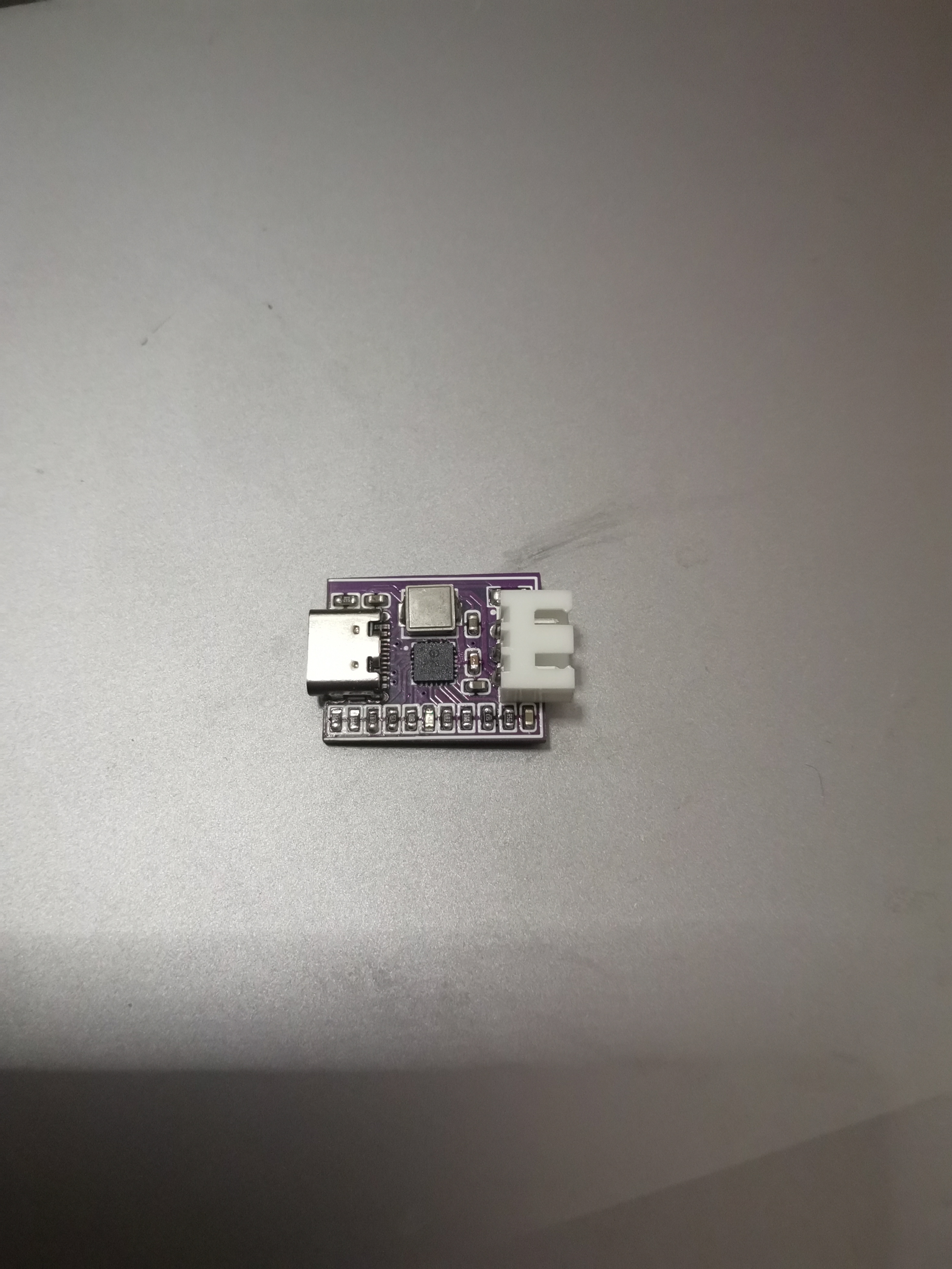
 Also bring out three XH 2.54 ports (4P, GVSS),
 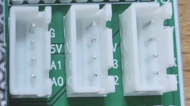 and two 2.54-pitch 4P interfaces for IIC pins. You can solder pin headers, female headers, or other 2.54-pitch terminals as needed.
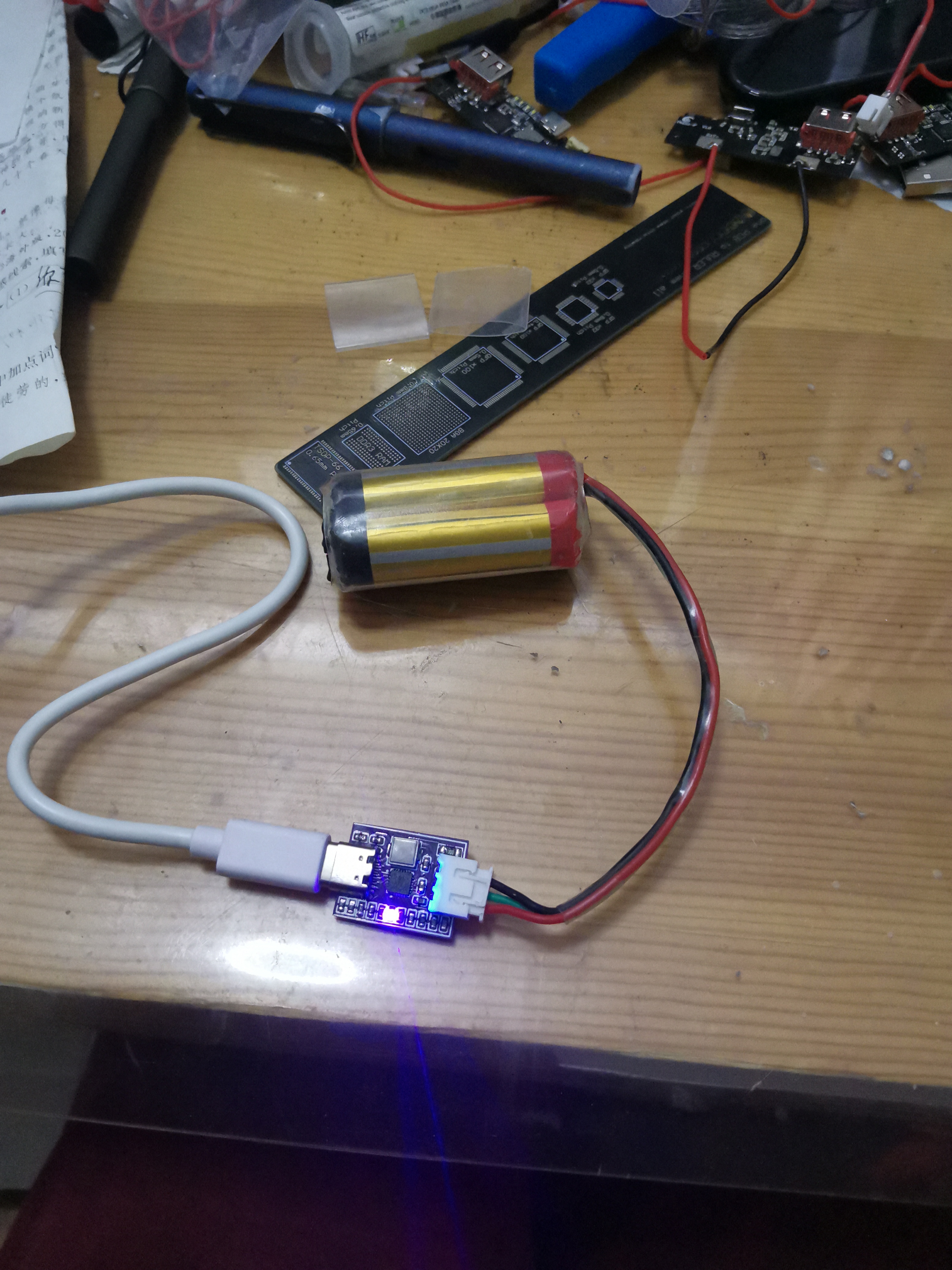
 The power supply can be the UNO's DC interface or soldered terminals. It is recommended that this power supply not exceed 10V, as the onboard voltage regulator chip on domestic UNO boards is of unstable quality, and the DRV8833 module has a withstand voltage of 10.8V. If controlling multiple motors, making a small car, controlling multiple servos, or using high-current servos such as the 995 or 996 servos, an external 5V power supply is required; you can also solder 5V power supply terminals for this purpose. The motor power supply is selected between 5V and VIN using a jumper cap.
 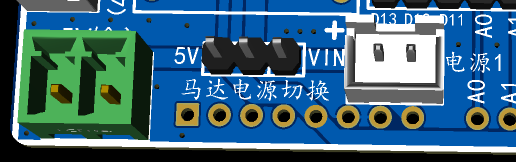 Motor pins can be soldered with header pins, XH 2.54 terminals, 2.54 screw terminals, etc., as needed.

All reference designs on this site are sourced from major semiconductor manufacturers or collected online for learning and research. The copyright belongs to the semiconductor manufacturer or the original author. If you believe that the reference design of this site infringes upon your relevant rights and interests, please send us a rights notice. As a neutral platform service provider, we will take measures to delete the relevant content in accordance with relevant laws after receiving the relevant notice from the rights holder. Please send relevant notifications to email: bbs_service@eeworld.com.cn.
It is your responsibility to test the circuit yourself and determine its suitability for you. EEWorld will not be liable for direct, indirect, special, incidental, consequential or punitive damages arising from any cause or anything connected to any reference design used.
Supported by EEWorld Datasheet
EEWorld
subscription
account

EEWorld
service
account

Automotive
development
community

Robot
development
community

About Us Customer Service Contact Information Datasheet Sitemap LatestNews


Room 1530, 15th Floor, Building B,
No.18 Zhongguancun Street,
Haidian District,
Beijing, Postal Code: 100190
China
Telephone: 008610 8235 0740
 京公网安备 11010802033920号

 HFBR-53D5EM


