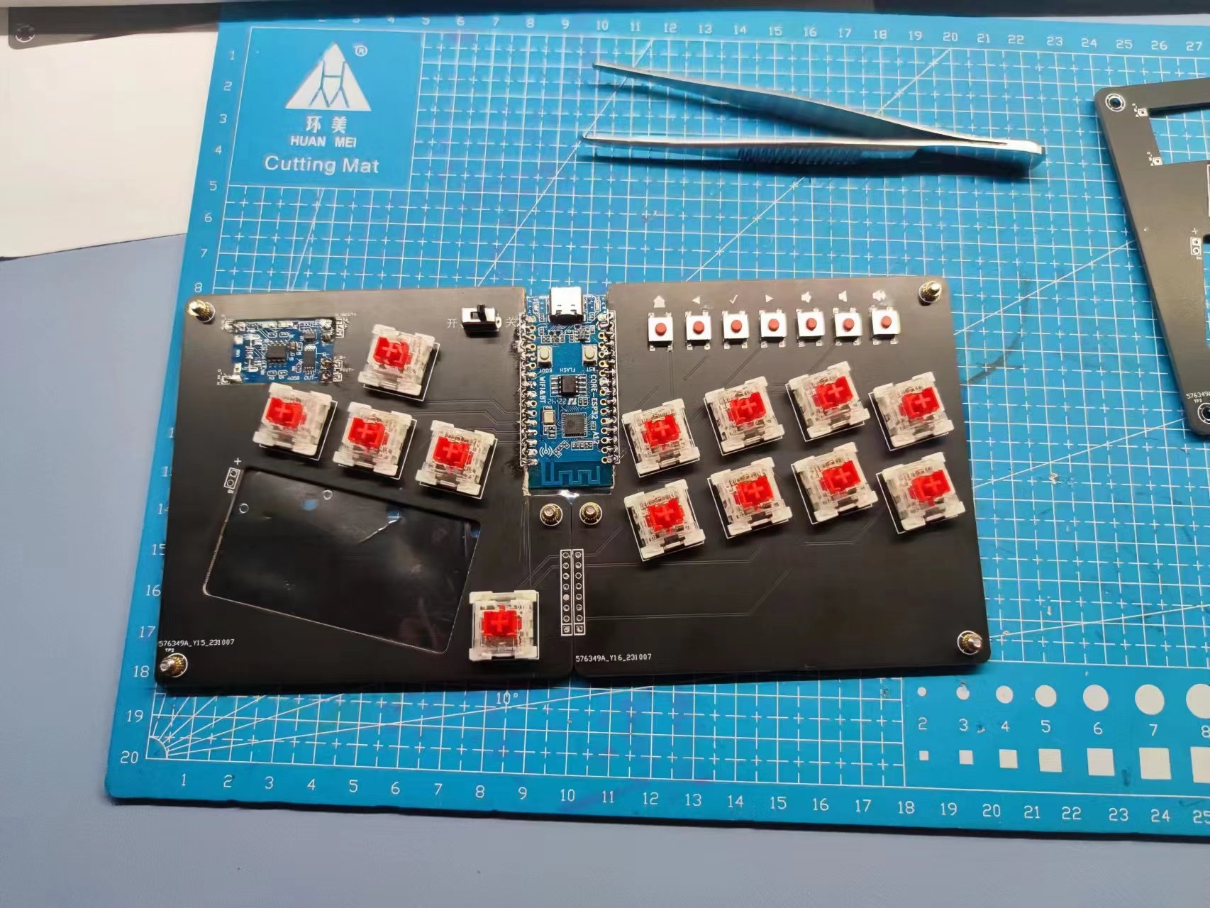
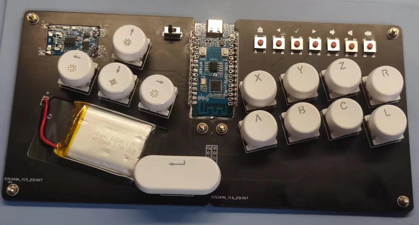
This is a simple Bluetooth gamepad project based on the ESP32-C3. It uses the Heze ESP32-C3 development board.
It's a Bluetooth gamepad resembling a hitbox.
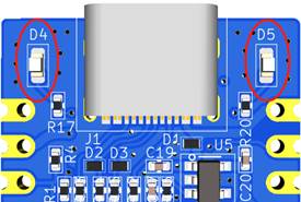
I saw a classmate make a hitbox using the RP2040 solution; it has mature firmware, a kit, and acrylic drawings, and the cost to order directly is around 200 RMB. After returning home, I wanted to make one too, but I didn't want a wired one, so I made this ugly thing using the ESP32. I also made a three-layer acrylic drawing, but given my poor skill level, I won't post it. Actually, it works without the acrylic frame. Let's talk about the drawbacks: 1. ESP32 Bluetooth requires about 80mA of current, which is quite power-consuming (and it's called BLE!). So next time I plan to make one using the NRF52832, which reportedly draws between 10-20mA. 2. Cherry buttons are cheap, but they're too tall; next time I'll use low-profile switches. 3. The high current draw results in a large battery. 4. It consists of two boards, left and right, connected by jumpers and screw holes. (The fun of getting freebies is insane!) 5. To keep the board as low as possible, I specifically used a stamp-hole soldering method, which required cutting the mounting holes on the two PCBs. I just cut them open with scissors. 6. The code is terrible. I failed to simulate an Xbox controller. My abilities, experience, and energy are limited, and I'm not a professional, so please be kind... The buttons use Cherry MX Red switches, and I bought a set of keycaps. I used a TP4056 charging module, embedded in the PCB. The battery is also embedded in the PCB. A PCB set consists of 5 boards. I used two layers stacked together to make the bottom cover. The cost of the acrylic was [not specified]. The left side of the switch uses a battery, and the right side is for charging the battery. Regarding I/O: Due to insufficient I/O interfaces, 8 buttons are directly connected to the I/O, and the remaining 12 buttons are scanned via a 3x4 matrix, occupying a total of 15 I/O to drive 20 buttons. Subtracting the right-side D5 LED (PIN13), and keeping the left-side D4 LED (PIN12) for indicator lights,
the approximate cost is as follows:
ESP32-C3 development board
9.9 yuan (free shipping ),
PCB
free shipping, 30
Cherry buttons 27 yuan (free shipping), totaling 0.9 * 13 = 11.7 yuan. TP4056 charging module 3 yuan (free shipping) , lithium battery 10 yuan (free shipping), keycaps 8 yuan (104 pieces, free shipping) , some small buttons (I don't remember the price) , screws and screw nuts 4 yuan (free shipping). The code is here: https://github.com/funnysteven/esp32-ble-gamepad/ There are some screenshots; just enjoy them.


PDF_esp32-c3-ble-gamepad-cherry_HITBOX.zip
Altium_esp32-c3-ble-gamepad-cherry_HITBOX.zip
PADS_esp32-c3-ble-gamepad-cherry_HITBOX.zip
BOM_esp32-c3-ble-gamepad-cherry_HITBOX.xlsx
97422
SP4533 power supply
SP4533 power supply
Multiple Safety Protections: Built-in charging and discharging power MOSFETs, with a fixed charging current of 1A. Features multiple safety protection functions including temperature compensation, over-temperature protection, overcharge and over-discharge protection, output overvoltage protection, output overload protection, and output short-circuit protection to ensure the safety of the chip and lithium-ion battery.
Power Detection and LED Indication: Detects power level and provides LED indication.
Intelligent Temperature Control and Over-Temperature Protection: Built-in intelligent temperature control with over-temperature protection.
Integrated Output Overvoltage Protection, Short-Circuit Protection, and Overload Protection: Multiple protections ensure the safety of the chip and lithium-ion battery.
Supports Trickle Charge and Zero-Voltage Charging: Supports trickle charge mode, allowing charging after the battery is fully discharged.
Simple Application Circuit: Requires only a few components for charging and discharging management.
Supports Flashlight Output: In addition to basic charging and discharging management, it also supports flashlight output functionality.
e3b40c81586ab41cd751bee6bc55e35d.mp4
PDF_SP4533 power supply.zip
Altium_SP4533 power supply.zip
PADS_SP4533 power supply.zip
BOM_SP4533 Power Supply.xlsx
97424
A smart curtain project based on the Liangshan School
The Liangshanpai-based smart curtain project is an integrated smart home system that combines multiple functions. Using the Liangshanpai development board as its core, the project automatically adjusts the opening and closing of the curtains by sensing environmental factors such as light and raindrops.
The Liangshanpai-based smart curtain project is a comprehensive smart home system that provides a convenient, comfortable, and energy-efficient home environment.
The project design encompasses the following aspects:
Hardware Design: The Liangshanpai development board is used as the core controller, connecting sensors and actuators to achieve automatic curtain control.
Software Design: Programming is done to implement automatic control, remote control, and voice control functions, while also considering a user-friendly interface.
Environmental Sensing: Installed light and rain sensors detect ambient light and raindrops, triggering the curtains to open and close.
Automated Control: The system automatically adjusts the curtains' opening and closing status based on preset conditions or user commands to maintain indoor comfort. Remote Control:
Users can control the curtains' opening and closing status conveniently and quickly via a remote control.
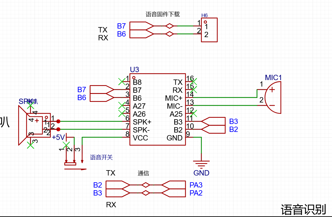
Voice Control: An integrated voice recognition module allows users to control the curtains' opening and closing status via voice commands.
Energy Saving and Environmental Protection: A low-power design is adopted to reduce energy waste, while also considering environmental factors such as the use of environmentally friendly materials.
Multi-Scenario Application: Applicable to various scenarios such as homes, offices, and hotels, meeting the needs of different users.
Safe and Reliable: Multiple security protection measures are employed to ensure the system's stability and security.
Scalability: Reserved interfaces facilitate future functional expansion and upgrades.
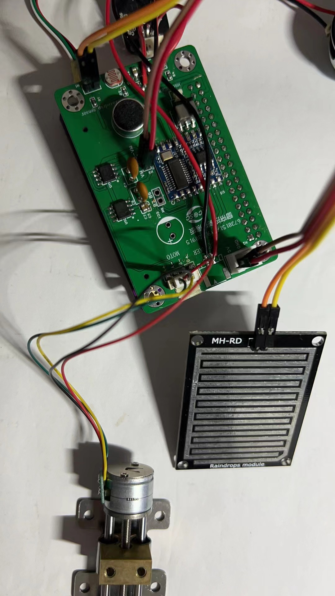
The PCB layout
includes a power interface, voice module, MI head, speaker, motor interface, driver, switch, infrared receiver, photosensitive sensor, and rain sensor.

Schematic diagram introduction:
Voice module
, infrared receiver,

motor driver,

photosensitive

sensor. Hardware introduction and functions:
Infrared receiver:
Receiving infrared signals: The infrared receiver can receive infrared signals and convert them into electrical signals.
Filtering noise: The infrared receiver can filter out surrounding noise, receiving only the required infrared signal.
Converting electrical signals: The photodiode inside the infrared receiver can convert the received infrared signal into an electrical signal.
Amplifying the signal: The converted electrical signal is usually weak and needs to be amplified by an amplification circuit.
Output signal: The processed electrical signal can be output through the output pin for use by subsequent circuits.
Compatible with multiple protocols: The infrared receiver is compatible with multiple infrared communication protocols, such as NEC and Philips.
Strong anti-interference capability: The infrared receiver has strong anti-interference capability and stable operation, and can work normally in complex environments.
Small size and easy installation: The infrared receiver head is small in size and lightweight, making it easy to install in various devices.
The voice module has the following features:
Voice recognition: The voice module can analyze human voice characteristics and voice signals, convert the voice signal into a digital signal, and automatically perform voice recognition.
Voice synthesis: The voice module can also convert text into a voice signal to achieve voice synthesis.
Natural language processing: Through natural language processing technology, the voice module can understand human language and respond accordingly.
Customizability: The voice module can be customized according to different application scenarios and needs to achieve more accurate voice recognition and more natural voice synthesis.
Universal interface: The voice module usually has a universal interface, which can be easily connected and integrated with other devices or systems.
High efficiency and energy saving: The voice module usually adopts a high-efficiency and energy-saving design, which can reduce power consumption and extend battery life.
The stepper motor driver has the following features:
Strong driving capability: The stepper motor driver has a strong driving capability and can meet the driving requirements of stepper motors of different specifications and models.
High control precision: By controlling the number of pulses and the pulse frequency, the stepper motor driver can achieve high-precision position control and speed control.
High Reliability: Stepper motor drivers employ advanced circuit design and manufacturing processes, ensuring high reliability and stability for extended periods of normal operation.
Fast Response: Stepper motor drivers offer rapid response capabilities, enabling quick control and adjustment of the stepper motor.
Multiple Control Methods: Stepper motor drivers support multiple control methods, such as pulse control, analog control, and serial communication control, allowing selection of the appropriate method for different application scenarios.
Energy Saving and Environmental Protection: Stepper motor drivers feature a low-power design, effectively reducing energy consumption and meeting energy conservation and environmental protection requirements.
A microphone is an electronic component that converts sound signals into electrical signals. Its primary function is to collect sound signals, including human speech and environmental sound signals. The microphone converts the collected sound signals into electrical signals, which are then transmitted to other devices such as computers and mobile phones.
Microphones play a crucial role in audio equipment, collecting and converting sound signals into electrical signals for transmission to other devices, enabling functions such as speech recognition and speech synthesis. Microphones can also be used for audio signal amplification, noise reduction, and echo cancellation to achieve better audio quality.
Photosensitivity refers to the ability of an object to react or change when exposed to light. This reaction or change can be physical or chemical.
In physics, some substances experience a change in resistance when exposed to light; this phenomenon is called the photoelectric effect. Photoresistors are made using this principle; they are semiconductor materials whose resistance changes when exposed to light. Photoresistors can be used to manufacture photoelectric sensors, photoelectric switches, and other photoelectric conversion devices. [
Image of a connected device]
89f962c626ee645652c211fe53858c05.mp4
Curtain Control System.rar
PDF_Smart Curtain Project Based on Liangshan School.zip
Altium_Smart Curtain Project Based on Liangshan School.zip
PADS_Smart Curtain Project Based on Liangshan School.zip
BOM_Smart Curtain Project Based on Liangshan School.xlsx
97425
Based on Liangshanpai handheld environmental monitoring device
The Liangshanpai Wireless Handheld Environmental Monitoring Device is a complex system integrating sensors, microcontrollers, and display modules.
Function Introduction:
This project involves data acquisition from temperature, humidity, air pressure, and hazardous gas sensors, real-time display, and independent power supply. It's a very comprehensive project requiring diverse technical knowledge. Here's a basic guide:
Hardware Selection:
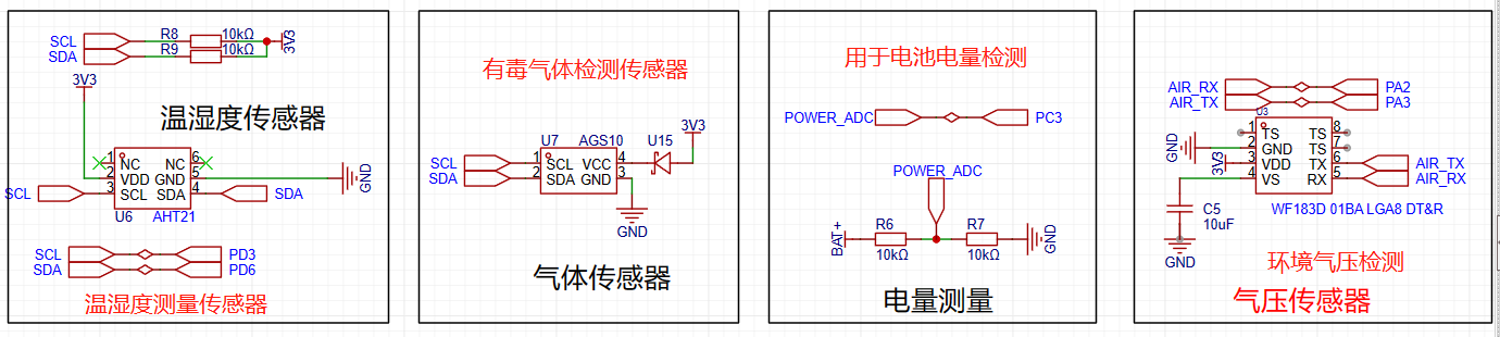
Temperature and Humidity Sensor: The DHT21 is an affordable and stable temperature and humidity sensor.
Air Pressure Sensor: The BMP183 is a high-precision, low-power air pressure sensor that can communicate with a microcontroller via an I2C interface.
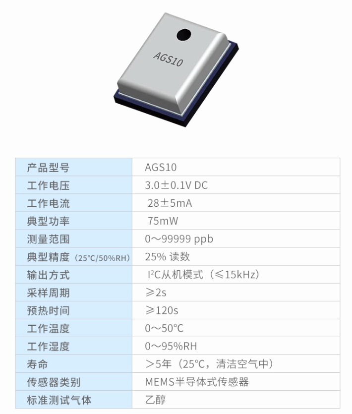
Hazardous Gas Sensor: The TVOC gas sensor AGS10 can detect smoke and alcohol.
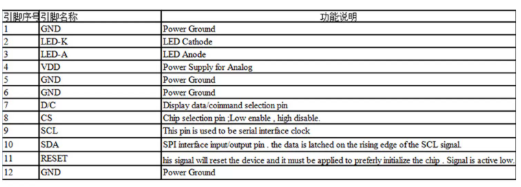
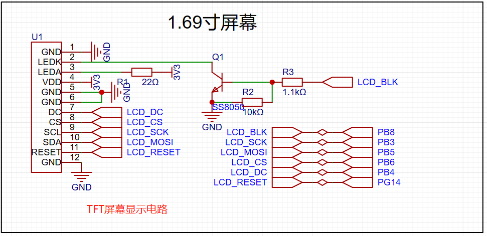
Display Module: If a low-power screen is needed, an OLED display can be considered. They are small, can display high-contrast images, and are very energy-efficient. A 1.69-inch TFT screen is used here.
Battery: 3.7V 5000MA lithium battery.
Programming:
The MDK platform is used.
Drivers are written for the sensors to acquire the collected data. The communication and operation of each device are understood by consulting its specifications.
For real-time display, a graphics library is used, and the collected data is displayed on the screen using the written code.
Human-Machine Interface Design: In addition to displaying data, user interface elements such as buttons and menus are designed. These elements can be implemented using LVGL or other graphics libraries.
Testing and Verification: After downloading the modified program to GD, comprehensive testing and verification are conducted through human-machine interaction to ensure the system's correctness and reliability. This includes testing the sensor accuracy under relatively stable environmental conditions to ensure reliability and stability during testing.
Optimization and Improvement: Based on the test results, some optimizations and improvements need to be made to the system to improve performance or resolve potential problems.
Documentation: Detailed documentation is prepared, including hardware specifications, software code, test results, etc., for future maintenance and improvement of the project.
Design Requirements:
The Liangshanpai Handheld Environmental Monitor is a portable device specifically designed for environmental monitoring. It is small and lightweight, battery-powered, freeing you from the hassle of power cords and allowing you to monitor the environment anytime, anywhere.
The device is equipped with temperature and humidity sensors to detect temperature and humidity data in real time, providing accurate data support for environmental analysis. In addition, it is equipped with a barometric pressure sensor to detect atmospheric pressure data, helping you understand the current atmospheric pressure conditions.
To provide a more comprehensive view of environmental conditions, the Liangshanpai handheld environmental monitor is equipped with a hazardous gas sensor for detecting harmful gases and other data. This sensor features high sensitivity and a fast response, enabling real-time monitoring of hazardous gas concentrations in the environment.
For convenient real-time data viewing, the Liangshanpai handheld environmental monitor features an easy-to-observe screen. Through touchscreen operation, you can easily view real-time data such as temperature, humidity, air pressure, and hazardous gases. Furthermore, the screen boasts a beautiful visual effect and a user-friendly interface, making it very convenient to use.
You can monitor environmental conditions anytime, anywhere, bringing greater convenience to your work and life.
Hardware Design:
The Liangshanpai handheld environmental monitor's hardware design includes the following main components:
Sensors:
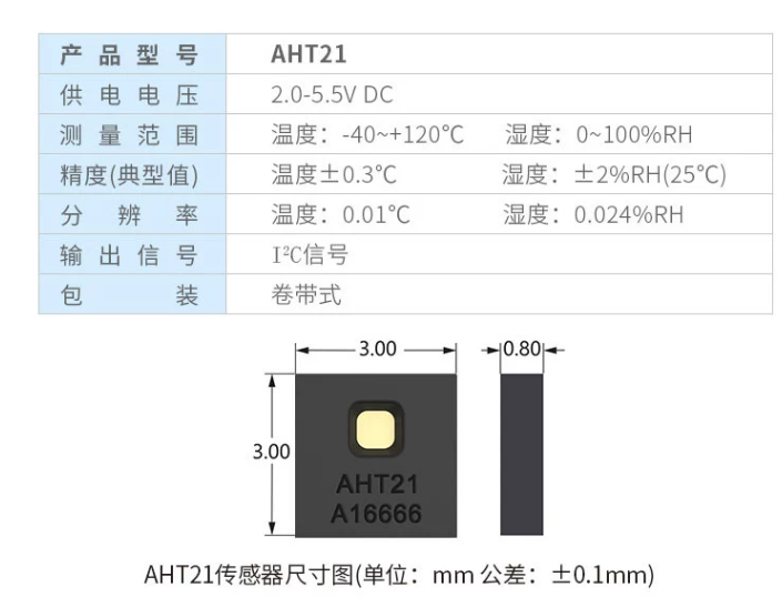
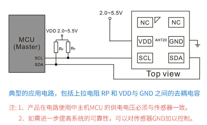
Temperature and Humidity Sensor: The AHT21 sensor is selected, which accurately measures temperature and humidity to meet environmental monitoring needs.
Air Pressure Sensor: The BMP183 sensor is selected, which measures atmospheric pressure and temperature, providing essential data for environmental monitoring.
Hazardous Gas Sensor: The TVOC gas sensor AGS10 is used to detect harmful gases such as smoke and alcohol.
Microcontroller Section:
The Liangshanpai handheld environmental monitor uses a GD32-type microcontroller to process sensor data and communicates with other GD32 microcontrollers via an I2C interface.
For better screen refresh, it is connected to the hardware SPI pin.
Display Module:
A TFT display screen is used to display the collected environmental data.
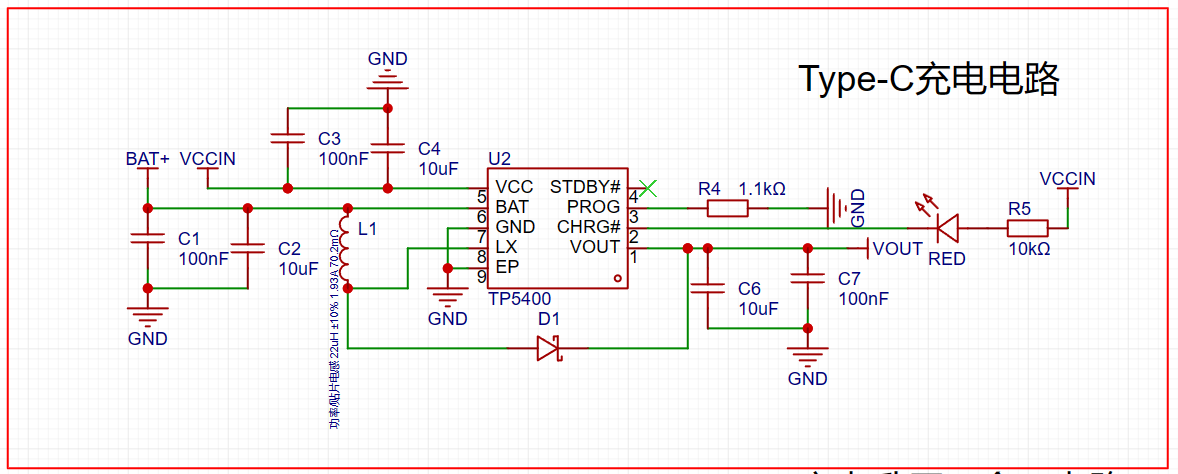
Battery Power Supply:
The Liangshanpai handheld environmental monitor uses a rechargeable lithium battery to ensure long-term use.
Peripheral Circuits:
In addition to the main functional modules, corresponding peripheral circuits need to be designed to support the operation of these modules, including power management circuits, filtering circuits, and protection circuits.
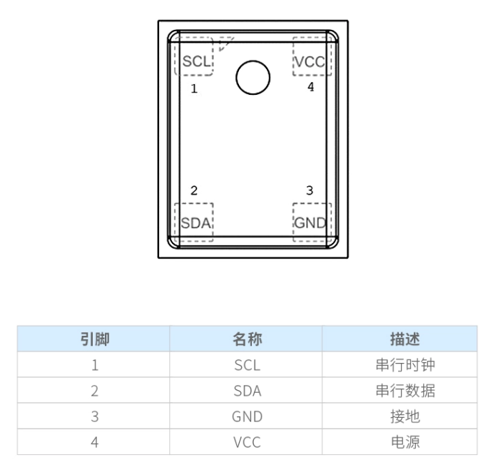
Hardware Introduction:
The AGS10 is a MEMS semiconductor intelligent TVOC gas sensor with calibrated digital signal output. It uses dedicated digital module acquisition technology and gas sensing technology, featuring high reliability and excellent long-term stability. This MEMS gas sensor features low power consumption, high sensitivity, fast response, high reliability and stability, low cost, and simple driving circuitry. It uses I2C digital output signals and integrates a high-performance semiconductor silicon-based resistive TVOC sensor. While the AHT21 and AHT10 temperature and humidity sensors from Auson are similar in function and performance, there are some differences. The AHT21 is a high-precision temperature and humidity sensor with digital I2C signal output, while the AHT10 is also a digital signal output sensor, but its accuracy and performance may differ from the AHT21.
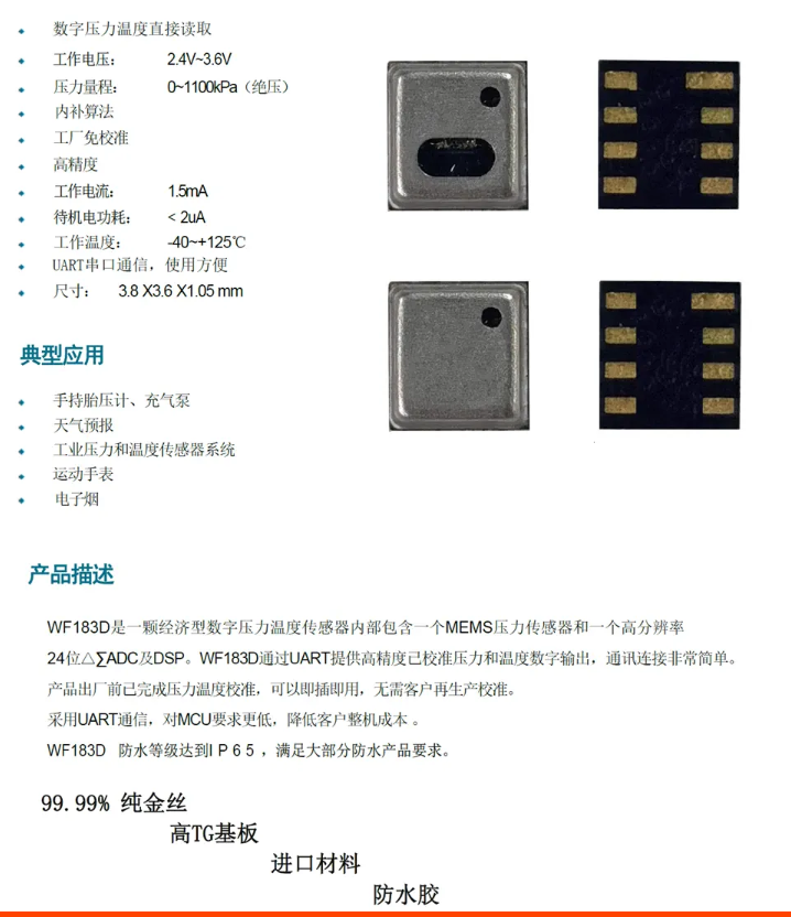
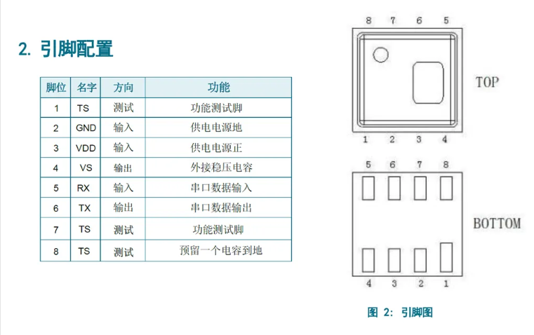
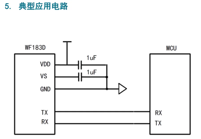
The AHT21 is compact and tiny, measuring only 3*3mm and 0.8mm in height, making it ideal for use in a variety of devices. It not only boasts excellent performance but also maintains good accuracy over a wide temperature range (-40℃ to 120℃). Furthermore, the AHT21 features I2C digital signal output for easy communication with microcontrollers or other devices. If you need to replace the AHT10 sensor and require digital I2C signal output, the AHT21 may be a suitable option. You can use the AHT21 to measure and monitor temperature and humidity and connect it to your devices for data transmission and processing. The 1.69-inch TFT display is a color high-definition IPS LCD bare screen with a resolution of 240x280. It uses an SPI interface for communication and is driven by an ST7789. IPS technology provides a wider viewing angle, allowing users to view the screen from different angles without color distortion or image shift. The SPI interface is a commonly used synchronous serial interface that allows communication between the microcontroller and other devices. The ST7789 is a common TFT LCD controller that supports the SPI interface and can be used to drive the 1.69-inch TFT display. The WF183D is an economical digital pressure and temperature sensor that internally contains a MEMS pressure sensor and a high-resolution 24-bit ΔΣ ADC and DSP. This means it can measure pressure and temperature very accurately and convert this data into digital signal output. Through the UART interface, the WF183D provides high-precision calibrated digital pressure and temperature output, making communication connections very simple. UART is a common serial communication protocol that allows communication between the microcontroller and other devices. Using the UART interface, you can easily connect the WF183D to your devices and read its measurement data. Performance


Framework

definition
circuit
sensor circuit
top-level

and bottom-level

operation video:
https://www.bilibili.com/video/BV1pc411Z7rV/?spm_id_from=333.999.0.0&vd_source=0e4686609dd9c60a63b3f7fe54080c03
324dddd13105f3a63904ce0d691b76cd.mp4
Handheld Environment Code .7z
PDF_Based on Liangshanpai Handheld Environmental Monitoring Device.zip
Altium_Based on Liangshanpai Handheld Environmental Monitoring Device.zip
PADS_Based on Liangshanpai Handheld Environmental Monitoring Device.zip
BOM_Based on Liangshanpai Handheld Environmental Monitoring Device.xlsx
97426
3D printer 4+2 axis motherboard
RP2040 4+2 axis 2226 onboard driver 2-axis pluggable
The 4+2 axis motherboard
features four 2226 pluggable adapters (2209)
paired with a 410 WiFi stick. It includes
a 6-24V to 5V and 5V to 3.3V
motherboard interface
,
two adjustable fans (one normally open, a total of five including series), three thermal position switches, five limit switches, and two 5V limit
switches. The heated bed heating rod interface is rated at 60W. The heated bed uses an external MOSFET.
USB expansion includes one USB port and two USB 4P/5P pins for connecting tool heads and additional devices.
RP2040 flashing
is possible via the WiFi stick and computer. Type-C can be used for flashing. For
power supply,
both Type-C and the connector can provide 5V for flashing and verification. The
6-24V connection automatically steps down to 5V and 3.3V
; voltage indicator lights up. Slight backflow at 5V causes 24V indicator lights to illuminate (this
is under review; the latest PCB uses 1-2).
PDF_3D Printer 4+2 Axis Motherboard.zip
Altium 3D Printer 4+2 Axis Motherboard.zip
PADS 3D Printer 4+2 Axis Motherboard.zip
BOM_3D Printer 4+2 Axis Motherboard.xlsx
97427
Based on CH32V203 (RISC-V) and AM32 brushless ESC
This tutorial provides a comprehensive guide to a brushless motor ESC based on AM32 firmware and ported to the RISC-V platform. The main controller is the CH32V203 RISC-V chip with a built-in internal comparator, which offers excellent cost performance.
I. Driven by
interest, I spent some time studying the BLHeli_S code and some excellent open-source hardware to learn about open-source ESCs. However, its 32-bit version is no longer open-source, so I looked into AM32 firmware. The code link is: https://github.com/AlkaMotors/AM32-MultiRotor-ESC-firmware. This project is constantly being updated; I downloaded version 1.95. For testing, I initially wanted to build a PCB directly, but found that the main control chip used was either out of stock or several or even over ten yuan expensive. Since I was also learning RISC-V recently, I decided to switch to a different platform, which ultimately yielded good performance and cost-effectiveness.
II. Detailed
Explanation of the Selected Main Control Chip: The WCH CH32V203F8U6 features a maximum clock frequency of 144MHz, 64KB FLASH, 20KB SRAM, one advanced timer, three general-purpose timers, and a built-in SysTick core (emphasizing the timers here, as the AM32 firmware requires six timers internally, detailed later). It also includes an OPA, which can be used directly as a comparator for zero-crossing detection. Overall, it easily handles ESC applications, and its price is relatively low. Although I have a sample chip, even the large-package sample only costs a little over three yuan.
For better testing, a 5V/1A BEC output was implemented on the board using an LDO. If the power is insufficient, a suitable DC-DC converter can be used instead. The MOS pre-driver uses the commonly used FD6288Q. The two manufacturers' chips available in the market have different power supply voltage ranges and low-voltage protection thresholds. The schematic directly uses the battery voltage for power supply, which should not be a problem for common 2-4S batteries.
The program has been ported to MRS, allowing direct debugging using WCH-LINKE. The BootLoader has also been ported; initial flashing requires using WCH-LINKE to flash the BootLoader, after which AM32 configuration tools can be used to configure and upgrade the ESC's code. The AM32 firmware uses six timers: an advanced timer driving PWM, capable of outputting complementary three-phase PWM; a commutation time counter; an advance commutation counter; a 10kHz timer interrupt for PID control and periodic tasks; an input capture and output compare timer for throttle signal detection and communication; and a timer for delay. V203, as mentioned earlier, has five timers, so the delay is replaced by a NOP instruction in the program. TIM1 is used for PWM output, TIM2 for throttle signal detection, TIM3 for advance commutation counting, TIM4 for commutation time counting, and SysTick for the 10kHz timer interrupt.
Simultaneously, zero-crossing comparison is performed using the internal OPA. The outputs of the two OPAs are connected together (they can also be disconnected, and their respective IO interrupts can be used directly), and simultaneously connected to PA2, using PA2 as the final entry point for the zero-crossing comparison interrupt. The IO port allocation is as shown below:

Note: In the actual schematic diagram, only voltage and temperature detection are performed. PA6 is not used for current detection, but instead has an LED connected. If needed, you can directly modify the connection of the sampling resistor and current amplification and connect it to PA6, and directly modify the relevant ADC program.
III. Usage Steps
1. Burn the BootLoader to the bare board using WCH-LINKE. If you are unsure about the soldering, you can first supply 5V from the 5V output of BEC, and then use LINK to connect the DIO and CLK on the board (remember to share a common ground) to burn the BootLoader.
2. After burning, you can use the AM32 host computer software. I am using version 1.82 (Esc_Config_Tool_1_82_WIN). However, it's important to note that the host computer and the ESC use a single-wire serial port. If you have an Arduino Nano board, you can directly flash a single-wire serial program onto it using BLHeliSuite. I directly ported its program to the CH32V003 (why this one? Mainly because I had the board and chip, and it's inexpensive!). Connect the LINK serial port directly to PD5 and PD6, then connect PC1 to the ESC's input interface. Power on the ESC, open the host computer, and click the following in sequence:

On the first connection, it will display "No EEPROM," because it's still a blank chip with no configuration values. Simply click "Send Default Settings" below to flash the default values. After successful flashing, power on again. Connect again and click "M1." This will display the default parameters we just flashed.

This proves that we have successfully flashed the BootLoader and can configure and upgrade the ESC program through the host computer.
3. Returning to the tool's FLASH interface, click "Load Firmware," select our compiled firmware, and then the "FLASH Firmware" button will pop up. Click it to start the program update. Wait for the program update to complete:

Now, power on again, connect the ESC, and you will find that the firmware has been successfully updated. Now you can test it.

For the specific meaning of these configuration values, please refer to the wiki in the repository, which is very detailed:
https://github.com/AlkaMotors/AM32-MultiRotor-ESC-firmware/wiki/ESC-Settings-Explained
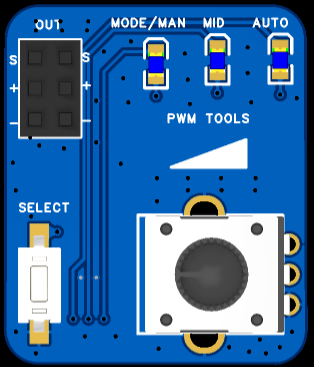
4. The following is the specific testing. The ported current version of AM32 supports PWM input, Dshot300, and Dshot600. So how do we generate these signals? There are some servo testers on Taobao, but they cannot output Dshot signals. So I went back to the CH32V003 and made another tester with it. By default, it is in PWM output mode upon power-on. The duty cycle can be adjusted by rotating the potentiometer. In PWM mode, a short press of the button can switch the PWM output between manual, intermediate value, and automatic scanning. Press and hold the button; the MODE/MAN light will flash slowly, indicating Dshot300 mode. Press and hold the button again; the MODE/MAN light will flash quickly, indicating Dshot600 mode. Long press to switch modes, short press to switch PWM output.
At this point, all preparations are complete, and you can connect the motor for testing.
IV. Attachments:
1. V003_OneWire.zip: Two-wire to single-wire serial port program;
2. Self-made servo tester data;
3. Host computer tools;
4. BootLoader program;
5. ESC PWM, Dshot300, and Dshot600 input no-load test;
6. Three signal waveforms for the test tool;
7. ESC main program reference: https://github.com/TianpeiLee/CH32V203_ESC.
V003_OneWire.zip
Servo_Test.zip
Esc_Config_Tool_1_82_WIN.zip
V203_bootloader_V11_PA0.zip
ESC_TEST.mp4
Servo_Tools.mp4
PDF_Based on CH32V203 (RISC-V) and AM32 brushless ESC (ESC).zip
Altium_based on CH32V203 (RISC-V) and AM32 brushless ESC (ESC).zip
PADS_Based on CH32V203 (RISC-V) and AM32 brushless ESC (ESC).zip
BOM_Based on CH32V203 (RISC-V) and AM32 brushless ESC (ESC).xlsx
97428
electronic


 京公网安备 11010802033920号

 0041.9113.6.3.0.036


