Function Introduction:
This project involves collecting data from temperature, humidity, air pressure, and hazardous gas sensors.
The collected data is displayed in real-time on a screen.
A 2.4G wireless communication module enables master-slave data interaction.
Battery-powered operation eliminates the need for power cords.
LVGL is used to achieve a visually appealing and user-friendly interface. Technical Requirements
: Temperature and humidity sensor: for detecting temperature and humidity
data; Air pressure sensor
: for detecting atmospheric pressure data; Hazardous gas sensor: for detecting hazardous gases and other data;
Screen: for real-time display of collected data;
Wireless communication: for sending data to a receiving device;
Handheld design: compact, battery-powered, eliminating the need for power cords; Charging and boost circuit design:
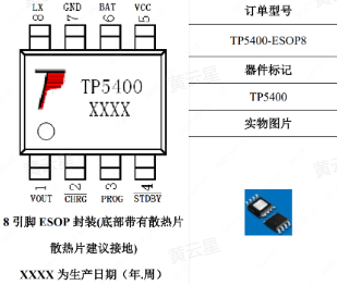
Based on project requirements, we need to design a compact, battery-powered environmental instrument. Using batteries necessitates considering charging and discharging. This case study uses the TP5400 lithium battery charging and boost control chip.
The TP5400 is a dedicated single-cell lithium-ion battery
charger . The charging section integrates high-precision voltage and
charging current regulators, pre-charge, charging status indication, and charging cutoff
functions , and can output a maximum charging current of 1A. The boost circuit
uses a VFM switching
DC/DC boost converter manufactured with CMOS technology, featuring extremely low no-load current. It boasts extremely low no-load power consumption (less than
10uA) and a boost output drive current capability of up to 1A. It requires no
external buttons and is plug-and-play.

Temperature and Humidity Sensor Design:
Temperature and humidity sensors are devices used to measure ambient temperature and relative humidity. They typically consist of a sensing element, signal processing circuitry, and an output interface.
Common sensing element technologies include thermistors, capacitive humidity sensors, and semiconductor sensors. Thermistors measure temperature based on the material's temperature
sensitivity , while capacitive humidity sensors utilize the relationship between humidity and capacitance. Semiconductor sensors can measure both temperature and
humidity, making them multifunctional sensors.
The signal processing circuit amplifies, filters, and linearizes the signal acquired by the sensing element, ensuring the accuracy and stability of the sensor output.
The output interface can be an analog signal interface or a digital signal interface, used to transmit the temperature and humidity data measured by the sensor to other devices for further processing or display.

Barometric Pressure Sensor Design:
Barometric pressure sensors are devices used to measure atmospheric pressure. It converts atmospheric pressure into an electrical signal through a sensing element, which
is then amplified, filtered, and linearized by a signal processing circuit, ultimately outputting a digital or analog signal related to air pressure.
Commonly used sensing element technologies include piezoresistive sensors (such as piezoelectric and resistive sensors), semiconductor sensors, and capacitive sensors.
Piezoresistive sensors: Piezoelectric sensors are based on the piezoelectric effect, where changes in applied pressure result in changes in charge or voltage; resistive sensors are based on the relationship between the resistance of a metallic material and the applied pressure. Both types of sensors indirectly measure air pressure by measuring changes in charge or resistance.
Semiconductor sensors: Semiconductor sensors utilize the relationship between the resistance of a semiconductor material and temperature and pressure. When the external air pressure changes, the resistance of the semiconductor material changes, and the air pressure is determined by measuring this change in resistance.
Capacitive sensors: Capacitive sensors utilize the relationship between capacitance, gap size, and the dielectric constant of the medium, inferring changes in air pressure by measuring changes in capacitance. They can directly measure air pressure with high accuracy.
Air pressure sensors are widely used in meteorological observation, climate research, air quality monitoring, aircraft navigation and altitude measurement, and air pressure control systems.
These sensors provide real-time and accurate barometric pressure data, helping people understand and predict weather changes and achieve precise altitude measurement and control.

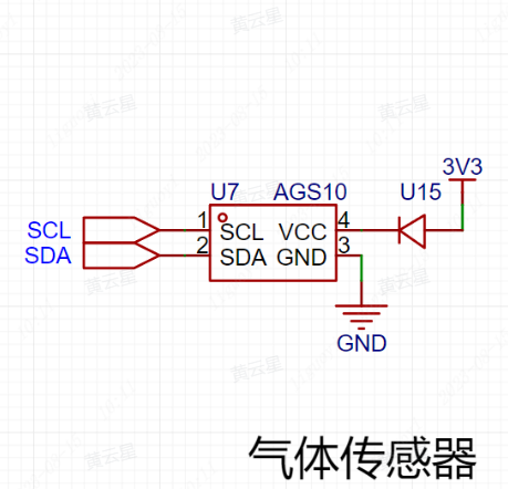
Hazardous gas sensors are devices used to detect and monitor the concentration of harmful gases in the environment. They are widely used in industrial safety, indoor air quality monitoring, and environmental pollution monitoring.
Hazardous gas sensors can detect and measure a variety of common harmful gases, including but not limited to carbon monoxide (CO), carbon dioxide (CO2), formaldehyde
(HCHO), ammonia (NH3), hydrogen (H2), hydrogen sulfide (H2S), benzene (C6H6), nitrogen oxides (NOx), and ozone (O3).
The working principle of the sensor varies depending on the sensor type and the harmful gas being detected. Common sensor technologies include chemical sensors, electrochemical sensors, infrared sensors, and semiconductor sensors.
Chemical sensors: Chemical sensors use specific chemical reactions to detect harmful gases. The sensor typically contains a sensitive layer that reacts specifically with the target gas. When the target gas is present, the resistance, capacitance, color, or optical properties of the sensitive layer change; the gas concentration is determined by measuring this change.
Electrochemical Sensors: Electrochemical sensors measure gas concentration based on the electrochemical reaction between a gas and an electrode. The sensor typically contains electrodes that interact with the target gas. When the target gas enters the sensor, an electrochemical reaction occurs, generating a specific current or potential change, thus enabling measurement.
Infrared Sensors: Infrared sensors utilize the specific infrared absorption characteristics of gases to detect gas concentration. The sensor emits infrared radiation into the gas sample, and the concentration information of the target gas is obtained by measuring the transmitted or absorbed infrared light.
Semiconductor Sensors: Semiconductor sensors detect gas concentration by utilizing the principle that the electrical properties of semiconductor materials change in the presence of a target gas. When the target gas enters the sensor, the resistance or conductivity of the semiconductor material surface changes, thereby measuring the gas concentration.
The accuracy, response time, sensitivity, and stability of hazardous gas sensors are important factors to consider when selecting a sensor. Depending on the specific application
requirements , sensors can be used alone or in conjunction with a monitoring system for timely alarms, data logging, and remote monitoring.
The maximum battery voltage is 4.2V, and the minimum operating voltage is 3.2V (to be determined based on specific circumstances).
The minimum operating voltage needs to be determined based on specific circumstances. It might not work at 3.4V
because the GD32's I/O ports are only compatible with a maximum of 5V; exceeding 5V will damage the I/O ports. The reference voltage for the voltage measurement peripheral ADC on the LCSC Liangshanpai development board is 3.3V. Therefore, if the ADC is used to directly measure the battery voltage, it cannot measure voltages above 3.3V.
The circuit diagram for power measurement is shown below.

2.4G Wireless Communication Interface Design:
This type of module typically has the following characteristics and functions:
2.4GHz Band: The 2.4GHz band is a commonly used wireless communication band with good penetration and long transmission distance, suitable for various wireless communication applications.
Transceiver Design: The transceiver design allows the module to simultaneously transmit and receive data, providing a more convenient wireless communication solution.
High-speed data transmission: 2.4G wireless transceiver modules typically offer high data transmission rates, meeting the needs of most applications, such as transmitting audio, video, and images.
Low-power design: To extend battery life or reduce power consumption, these modules typically employ a low-power design for longer operating time.
Ease of use: 2.4G wireless transceiver modules usually provide easy-to-use interfaces and protocols, facilitating user configuration and control.
Multiple application areas: These modules can be widely used in wireless remote control, wireless data transmission, wireless sensor networks, and other fields, providing stable and reliable wireless communication capabilities for various devices and systems.

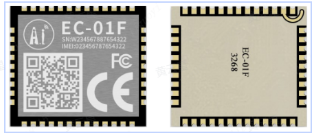
NBIoT (Narrowband Internet of Things) modules are hardware modules specifically designed for narrowband Internet of Things (IoT) communication. They offer a power-saving, low-cost, long-range communication solution suitable for IoT devices and applications .
Here are some key features and functions of NBIoT modules:
Narrowband communication: NBIoT modules utilize narrowband communication technology, which offers advantages such as low power consumption and long communication distance. Narrowband communication technology effectively solves the energy consumption and coverage limitations faced by IoT devices.
High coverage capability: NBIoT modules can provide extensive coverage in complex environments, including indoors, outdoors, and underground. It can penetrate walls and obstacles to achieve long-distance communication.
Low-power design: The NBIoT module is designed with power optimization in mind to extend device battery life. It employs a low-power mode, activating the wireless module only during data transmission and remaining in sleep mode at other times.
Data transmission security: The NBIoT module provides secure data transmission guarantees. It supports security mechanisms such as encryption and authentication to ensure the security of devices and communication data.
Wide application: The NBIoT module can be applied to various IoT devices, such as smart cities, smart agriculture, smart homes, smart energy management, and smart transportation. It provides these applications with long-distance, low-power, and low-cost communication solutions.
Compatibility: NBIoT modules typically have good compatibility and can be integrated with other devices and systems. It supports the standard NBIoT communication protocol, connecting and interacting with existing networks and platforms.
1. Screen display driver:
Generally, when we receive a screen, we first need to port the official code provided by the manufacturer for screen lighting testing. The hardware SPI and software SPI porting steps for this screen are already in the LCSC development board module porting manual.
After porting the code, carefully observe whether the color refresh is correct (color difference), whether the display method is correct (landscape/portrait), and whether the color data refresh is
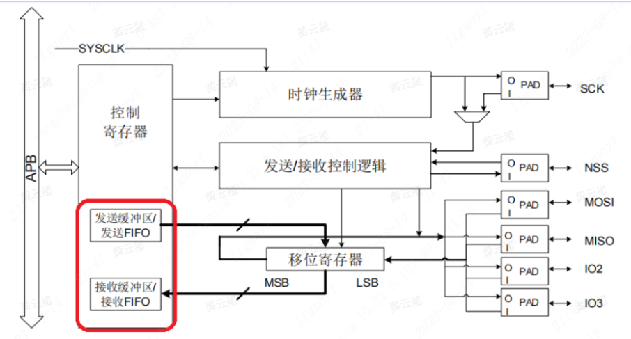
normal (errors, omissions, flickering). If there are problems even if the wiring meets the device requirements, consult the manual. The manual reveals that
the GD32F470's SPI has a FIFO, so at the end of data transmission, you need to wait for the data transmission to complete before releasing the chip select. Otherwise, it can easily cause screen display
problems (generally, the emptyness of the buffer is used as the criterion for transmission, thereby improving transmission efficiency).

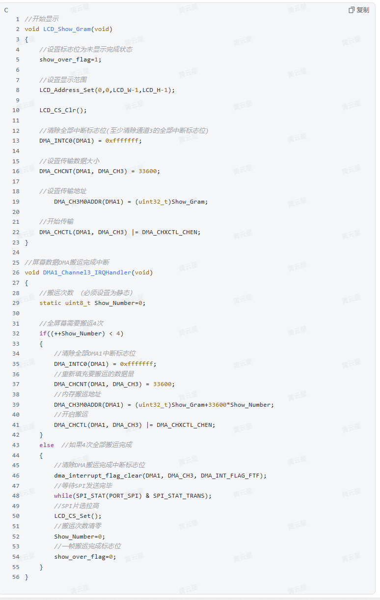
1.1 Using DMA for SPI screen refresh.
The general process for using DMA is to first configure the corresponding DMA and channel for the peripheral, and then configure the automatic or software-triggered DMA transfer direction.
However, we need to determine the amount of data to be transmitted based on the screen's pixel count. The maximum data transfer volume of DMA is 65535. The case uses a 1.69-inch screen with a pixel count of 240x280, meaning all pixels are 240 + 280 = 67200, which exceeds the maximum DMA transfer volume. Therefore, all pixel data is transmitted in two parts, i.e., 67200 / 2 = 33600.
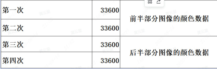
However, I set the DMA data width to 8 bits, meaning 8 bits of data are transferred at a time. My 1.69-inch screen is a TFT color screen, and each pixel requires 16 bits of color data. With DMA set to 8-bit transmission and each screen pixel requiring 16 bits of data, the actual amount of data transferred is the total pixel size 2!, or 67200 + 2 = 134400. Therefore, to display one frame of image, we need to transfer the data 4 times!
The
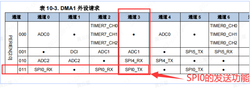
hardware SPI in this example uses SPI0 (which needs to be determined based on the pin used). According to the DMA request table in the datasheet, to use DMA to move data from hardware SPI0, we can only use DMA1 channel 3 or channel 5. This example uses DMA1 channel 3.
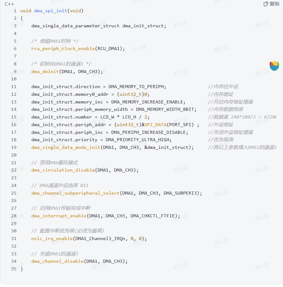
To use the hardware SPI's DMA function, DMA must be enabled. This is divided into transmit enable and receive enable. Here, we only need to move screen data to the screen, so we use the hardware SPI's DMA transmit enable. (For other specific parameters, please refer to the code project file in the physical verification section.)

After DMA and SPI initialization configuration, the quick operation for transferring again is: clear the flags, set the transfer amount, set the transfer address, and start the transfer.
Regarding the explanation of clearing all interrupt flags:
because the hardware SPI I'm using is DMA1 channel 3, it's actually only necessary to write (0x2f << 22) to the DMA_INTC0 register. For convenience, I directly set all the settable bits in the register to 1.

Regarding the transfer address:
A full-screen buffer requires 240 + 280 = 67200 bytes. We can first modify the data in the buffer to the content to be displayed, and then update it uniformly on the screen. The simplest method is to define an array of size 67200, write the data we want to update into it, and then send it to the screen all at once, equivalent to image refresh;
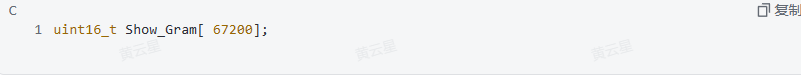
however, our internal RAM is limited and needs to be reserved for other RAM variables that require high-speed access. Therefore, here we use the external SDRAM (32MB) on the device.

In main.c, during initialization, write the following code: (Remember to import the header file)


1.2 Modify the display function


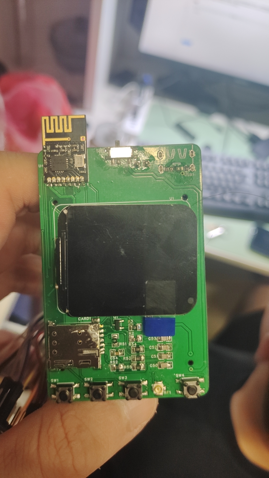
Physical diagram
Key program description
Temperature and humidity module implementation
Because the AHT20 temperature and humidity sensor uses a standard IIC interface, we can communicate with it using either software IIC or hardware IIC. Software IIC can be used with any general purpose input/output (GPIO) pin, while hardware IIC requires specific pins. This case uses software IIC, which can use any available pin as the IIC interface.
/********************************************************************
Function name: aht21_gpio_init
Function description: Initializes the IIC pins of the AHT21
Function parameters: None
Function return: None
Author: LCKFB
Remarks:
**/
void aht21_gpio_init(void)
{
// Enable pin clocks for SDA and SCL
rcu_periph_clock_enable(RCU_AHT21_SCL);
`rcu_periph_clock_enable(RCU_AHT21_SDA);
` // Sets the SCL pin mode to pull-up output.
`gpio_mode_set(PORT_AHT21_SCL, GPIO_MODE_OUTPUT, GPIO_PUPD_PULLUP, GPIO_AHT21_SCL);
` // Sets the pin to open-drain mode with a toggle speed of 2MHz.
`gpio_output_options_set(PORT_AHT21_SCL, GPIO_OTYPE_OD, GPIO_OSPEED_2MHZ, GPIO_AHT21_SCL);
` // Sets the pin output to high level to wait for the SCL signal. `
gpio_bit_write(PORT_AHT21_SCL, GPIO_AHT21_SCL, SET);
` // Sets the SDA pin mode
. `gpio_mode_set(PORT_AHT21_SDA, GPIO_MODE_OUTPUT, GPIO_PUPD_PULLUP, ...` GPIO_AHT21_SDA);
gpio_output_options_set(PORT_AHT21_SDA, GPIO_OTYPE_OD, GPIO_OSPEED_2MHZ, GPIO_AHT21_SDA);
gpio_bit_write(PORT_AHT21_SDA, GPIO_AHT21_SDA, SET);
}
/**
Function name: aht21_device_init
Function description: Initializes AHT21 via command bytes
Function parameters: None
Function return: None
Author: LCKFB
Remarks: None
**/
void aht21_device_init(void)
{
uint8_t device_addr = 0x70;// Device address
uint8_t init_command = 0xBE;// Initialization command
uint8_t init_command_parameter_1 = 0x08;// Acquisition parameter 1
uint8_t init_command_parameter_2 = 0x00; // Acquire parameter 2
IIC_Start();
IIC_Send_Byte(device_addr); // Send device address
if( I2C_WaitAck() == 1 ) printf("warning -5
");
IIC_Send_Byte(init_command); // Send initialization command
if( I2C_WaitAck() == 1 ) printf("warning -6
");
IIC_Send_Byte(init_command_parameter_1); // Send initialization parameter 1
if( I2C_WaitAck() == 1 ) printf("warning -7
");
IIC_Send_Byte(init_command_parameter_2); // Send initialization parameter 2
if( I2C_WaitAck() == 1 ) printf("warning -8
");
IIC_Stop();
}
/**
Function name: aht21_read_data
Function description: Reads temperature and humidity
function Parameters: None
Function return: 1: Uncalibrated 2: Read timeout 0: Read successful
Author: LCKFB
Remarks: None
**/
char aht21_read_data(void)
{
uint8_t data[6] = {0};
uint32_t temp = 0;
uint8_t aht21_status_byte = 0;
uint8_t timeout = 0;
// Read the status of AHT21
aht21_status_byte = aht21_read_status();
// If uncalibrated, return 1
if( (aht21_status_byte & (1<<3)) == 0 )
{
aht21_device_init();
delay_1ms(50);
return 1;
}
// Send the acquisition command
aht21_send_gather_command();
do
{
delay_1ms(1);
timeout++;
// Read the AHT21 status
aht21_status_byte = aht21_read_status();
}while( ( ( aht21_status_byte & (1<<7) ) != 0 ) && ( timeout >= 80 ) );
// If the read times out, return 2
if( timeout >= 80 ) return 2;
IIC_Start();
IIC_Send_Byte(0x71);
if( I2C_WaitAck() == 1 ) printf("error -1
");
IIC_Read_Byte();// Read the status, no need to save
IIC_Send_Ack();
// Read 6 bits of data
data[0] = IIC_Read_Byte();
IIC_Send_Ack();
data[1] = IIC_Read_Byte();
IIC_Send_Ack();
data[2] = IIC_Read_Byte();
IIC_Send_Ack();
data[3] = IIC_Read_Byte();
IIC_Send_Ack();
data[4] = IIC_Read_Byte();
IIC_Send_Ack();
data[5] = IIC_Read_Byte();
IIC_Send_Nack();
IIC_Stop();
// Integrate humidity data
temp = (data[0]<<12) | (data[1]<<4);
temp = temp | (data[2]>>4);
// Convert humidity data
// 2 to the power of 20 = 1048576
humidity = temp / 1048576.0 * 100.0;
// Integrate humidity data
temp = ( (data[2]&0x0f)<< 16 ) | (data[3]<<8);
temp = temp | data[4];
//Convert humidity data
//2 to the power of 20 = 1048576
temperature = temp / 1048576.0 * 200.0 - 50;
return 0;
}
### The
WF183D pressure sensor is driven by a serial port for communication. Its default communication format is as follows: In the hardware design section, we connected the serial port pin of the sensor to PA2PA3 (USART1) of the LCSC Liangshanpai development board. Therefore, before use, we need to initialize the pins for serial communication. The communication configuration follows the requirements of the WF183D datasheet:
/**
Function Name: wf183d_gpio_config
Function Function: Initializes the WF183D barometric pressure sensor
Input Parameters: None
Function Return: None
Author: LCKFB
Remarks: Default baud rate 9600
**/
void wf183d_gpio_config(void)
{
/ Enable clock /
rcu_periph_clock_enable(BSP_WF183D_USART_TX_RCU); // Enable serial clock
rcu_periph_clock_enable(BSP_WF183D_USART_RX_RCU); // Enable port clock
rcu_periph_clock_enable(BSP_WF183D_USART_RCU); // Enable port clock
/ Configure GPIO multiplexing function /
`gpio_af_set(BSP_WF183D_USART_TX_PORT,BSP_WF183D_USART_AF,BSP_WF183D_USART_TX_PIN);
gpio_af_set(BSP_WF183D_USART_RX_PORT,BSP_WF183D_USART_AF,BSP_WF183D_USART_RX_PIN);
` / Configure GPIO mode /
/ Configure TX to multiplexed pull-up mode / `
gpio_mode_set(BSP_WF183D_USART_TX_PORT,GPIO_MODE_AF,GPIO_PUPD_PULLUP,BSP_WF183D_USART_TX_PIN);`
/ Configure RX to multiplexed pull-up mode / `
gpio_mode_set(BSP_WF183D_USART_RX_PORT,` GPIO_MODE_AF,GPIO_PUPD_PULLUP,BSP_WF183D_USART_RX_PIN);
/ Configure TX as push-pull output 50MHz /
gpio_output_options_set(BSP_WF183D_USART_TX_PORT,GPIO_OTYPE_PP,GPIO_OSPEED_50MHZ,BSP_WF183D_USART_TX_PIN);
/ Configure RX as push-pull output 50MHz /
gpio_output_options_set(BSP_WF183D_USART_RX_PORT,GPIO_OTYPE_PP, GPIO_OSPEED_50MHZ, BSP_WF183D_USART_RX_PIN);
/ Configure serial port parameters /
usart_deinit(BSP_WF183D_USART); // Reset serial port:
`usart_baudrate_set(BSP_WF183D_USART, 9600);` // Set baud rate:
`usart_parity_config(BSP_WF183D_USART, USART_PM_NONE);` // No parity bit:
`usart_word_length_set(BSP_WF183D_USART, USART_WL_8BIT);` // 8 data bits:
`usart_stop_bit_set(BSP_WF183D_USART, USART_STB_1BIT);` // 1 stop bit
: `usart_enable
(BSP_WF183D_USART);` // Enable serial port:
`usart_transmit_config(BSP_WF183D_USART,USART_TRANSMIT_ENABLE);` // Enables serial port transmission.
`usart_receive_config(BSP_WF183D_USART,USART_RECEIVE_ENABLE);` // Enables serial port reception.
/* Interrupt configuration */ `
nvic_irq_enable(BSP_WF183D_USART_IRQ, 1, 2);` // Configures interrupt priority.
`usart_interrupt_enable(BSP_WF183D_USART,USART_INT_RBNE);` // Read buffer not empty interrupt and overflow error interrupt.
`usart_interrupt_enable(BSP_WF183D_USART,USART_INT_IDLE);` // Idle detection interrupt
.


 京公网安备 11010802033920号

 1136-1042-18R


