This project describes
a PC device designed based on the Raspberry Pi CM4 core board, running an Arm64 Linux system. Peripherals include:
a 5-inch 800x480 capacitive touchscreen, a MIPI interface
, an HDMI interface (supporting 4K 60fps according to Raspberry Pi's description),
a wired Ethernet port (for fast LAN access)
, two USB 2.0 ports (the CM4 only has one USB 2.0 port; these two are extended using a hub chip),
a MIPI webcam interface (supporting Raspberry Pi webcams)
, an M.2 4G interface (connecting to the USB 2.0 interface)
, an SD card slot (for SD card booting),
a Type-C power OTG interface, and
a Type-C power USB 2.0 interface
(the two Type-C interfaces cannot be used simultaneously; interface selection is controlled by BOOT. OTG master/slave mode is controlled by USBID. If BOOT mode is enabled, all USB 2.0 ports except OTG will be unavailable).
Raspberry Pi 40-pin pin configuration.
Video 1:
Video 2: https://www.bilibili.com/video/BV1eb4y1K7jw/ Open
Source License
: GPL 3.0
Project Attributes:
This project is being publicly released for the first time and is my original work. This project has not won any awards in other competitions.
Future Uses:
Using Python to programmatically programmatically burn, configure, and debug the microcontroller;
using ADB to debug Android devices; using SSH to remotely control Android devices.
SDR Host
Computer Software Instructions:
Burning the System
: Prepare an SD card as the system disk.
Download the Raspberry Pi system burning software. Download address: https://www.raspberrypi.com/software/

Select the 64-bit desktop system.
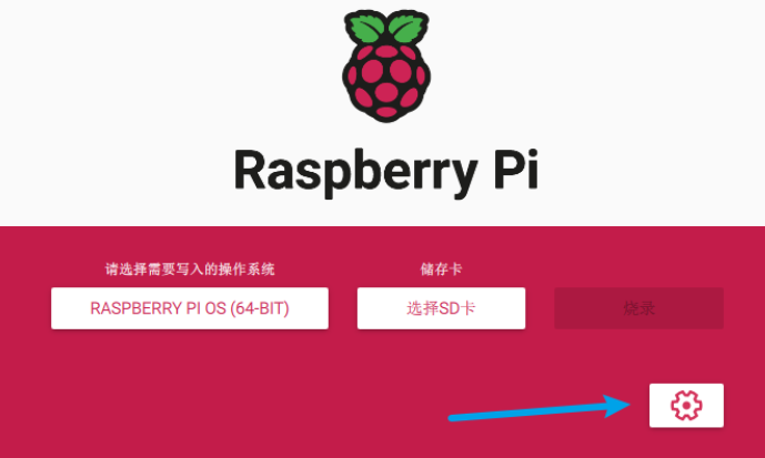
Open settings.
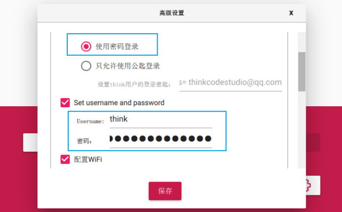
Open SSH.

Set the username and password, and WiFi connection information.
Click save, then click burn.
After burning, insert the SD card into the motherboard and power on. If normal, the Raspberry Pi will connect to your network; one status light will be constantly on, and the other will flash approximately every 5 seconds.
If it does not automatically connect to WiFi, try connecting the network port with an Ethernet cable.
The Raspberry Pi does not display the MIPI screen by default; a driver needs to be installed.
To drive
the MIPI display
, log in to the Raspberry Pi via SSH.
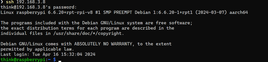
The Raspberry Pi MIPI interface driver is available at this website: https://datasheets.raspberrypi.com/.
Use the wget command to download the driver and save it to the specified location.

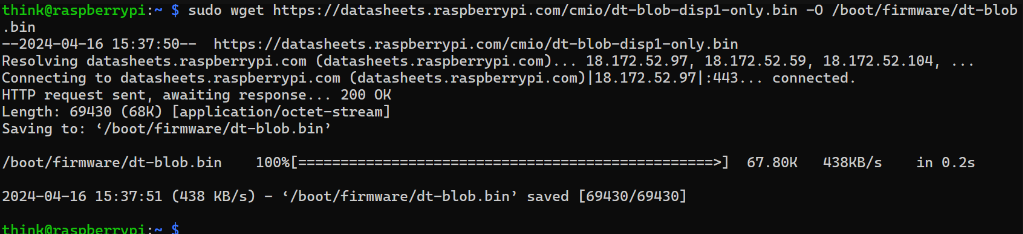
Restart the Raspberry Pi.

After restarting, the MIPI screen will display. The startup process may be a bit slow,
with a black screen and only a blinking cursor in the upper left corner (encountered in newer systems).
This is due to insufficient power supply, possibly due to the new system. I am using 5V/3.1A. The software needs to restart after startup for the screen to display.
For touch input
, use commands to enter the system settings interface

and open the I2C
interface. Open the I2C
project .
Motherboard v3
modifications: Remove camera, remove PCIe, remove RTC, rearrange layout, recalculate USB impedance
. High-speed interfaces:
USB,
MIPI,
HDMI,
Ethernet.
Motherboard v2
modifications: Remove USB OTG, re-segment internal power layers, complete signal loop
verification.
No MIPI,
No PCIe
, No USB,
OK touch,
OK MIPI,
OK HDMI
, OK Ethernet
, OK SD.
Motherboard v1
verification:
No camera,
No SSD,
No USB interface , OK
display .
HDMI
OK, Ethernet
OK. SD Card
Design Considerations:
I'm using a Raspberry Pi CM4 4G WiFi Lite version (the baseboard doesn't have a WiFi module). This device doesn't need to run for extended periods, and there are no industrial requirements, so I didn't choose the version with eMMC. I'm using SD card booting, which makes it easier to replace the SD card and change the system. I don't have the spare money to test the CM4 with eMMC, since even my version costs 580 yuan. For
the 4G network card, I'm using Quectel's EM05, which is suitable. Since the CM4 doesn't have USB 3.0, there's no need for a module with USB 3.0. Theoretically, it can use 5G, but at 2.0 speed.
I've reserved two antenna SMA connectors to IPEX connectors to connect the Raspberry Pi's WiFi and 4G modules. However, GNSS also needs an antenna, so I'll connect one of the WiFi and 4G antennas to the GNSS as needed. After all, WiFi and 4G can be used separately, or directly connected to 4G. The WiFi uses the built-in or internal FPC antenna.
The motherboard is a 4-layer board. The JLC04161H-7628 (generally recommended/free)
extended version of the stacked structure has been abandoned because the desired USB male connector is out of stock, so we have to find another way.


 京公网安备 11010802033920号

 DMYG-GJS-LM


