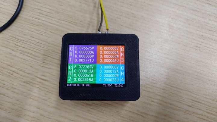
Each channel has four display parameters: 1. Voltage, 2. Current, 3. Power, and 4. Joule heat.
Some people might think that a desktop charger doesn't need much precision, and using a 32-bit ADC is a waste. Let me explain: this ADC chip isn't very expensive; you can buy a used one for around 10 RMB on Taobao. I bought a few before, designed a test board, debugged the program, and then it just sat there gathering dust. Recently, I was bored and decided to tinker with some things, hence this project.
The board program is very casual; I just wanted it to work, so it's a bit rough, and the code is rather poor, so I won't open-source it.
The total cost of the board is around 40 RMB, excluding shipping. Thanks to JLCPCB for letting me get it for free.
This ADC chip can output a built-in reference voltage and also output several constant current sources. I tested it before, and the constant current accuracy is about the same as described in the manual—not very high—so I didn't implement it.
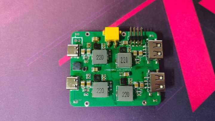
The slower the ADC sampling speed, the more stable the data. Value fluctuations and output ripple are related to layout and other factors. In my setup, the bottom layer has more DC-DC converters, and the ADC chip is on the top layer, which might cause some interference. To save time, I designed both parts on one board, but there's a complete ground plane in between for isolation. If you're interested, you can try designing two boards and connecting them.
The ADC sampling speed is quite low; switching between the 8 sampling channels takes a considerable amount of time, so the screen refreshes approximately once per second.
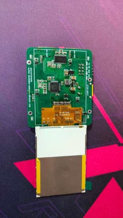
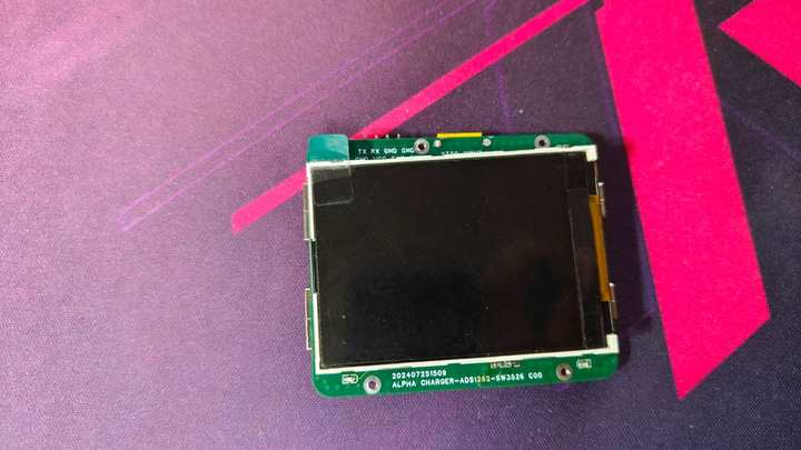
The screen used is a silkscreened T240IT010, driven by SPI and DMA.
The input interface uses an XT30, with a continuous current of 15A, 24V input, and a maximum power of over 300W, making it relatively safe.
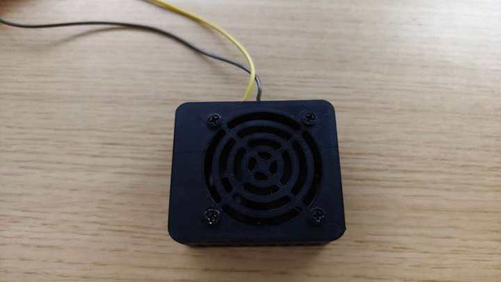
The fan selected is a 24V silent fan, size 5050, thickness less than or equal to 10mm.
Special note:
Please replace R65, R67, R69, and R71 with 1/18K (or even 1/1000) voltammetric capacitors; please replace R66, R68, R60, and R72 with 1/1000 voltammetric capacitors (or even 1/1000) voltammetric capacitors. Please use C0G capacitors for the 4.7nF capacitor in C4 (other capacitors can be used, but C0G is recommended).
SW3526_CHARGER MAIN.hex
VID20240731165635.mp4
PDF_4-channel high-precision desktop charger.zip
Altium 4-channel high-precision desktop charger.zip
PADS_4-channel high-precision desktop charger.zip
BOM_4-channel high-precision desktop charger.xlsx
93400
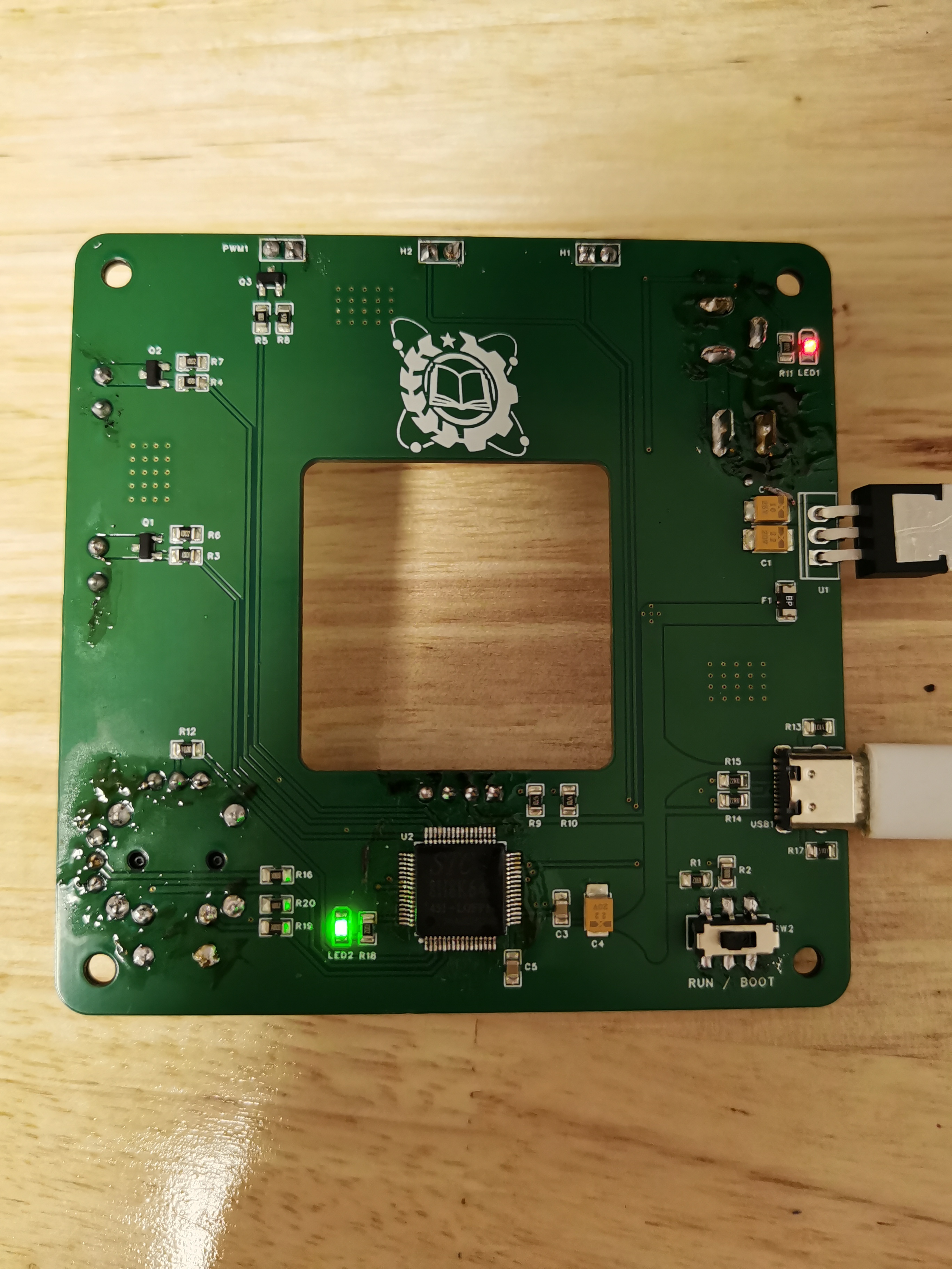
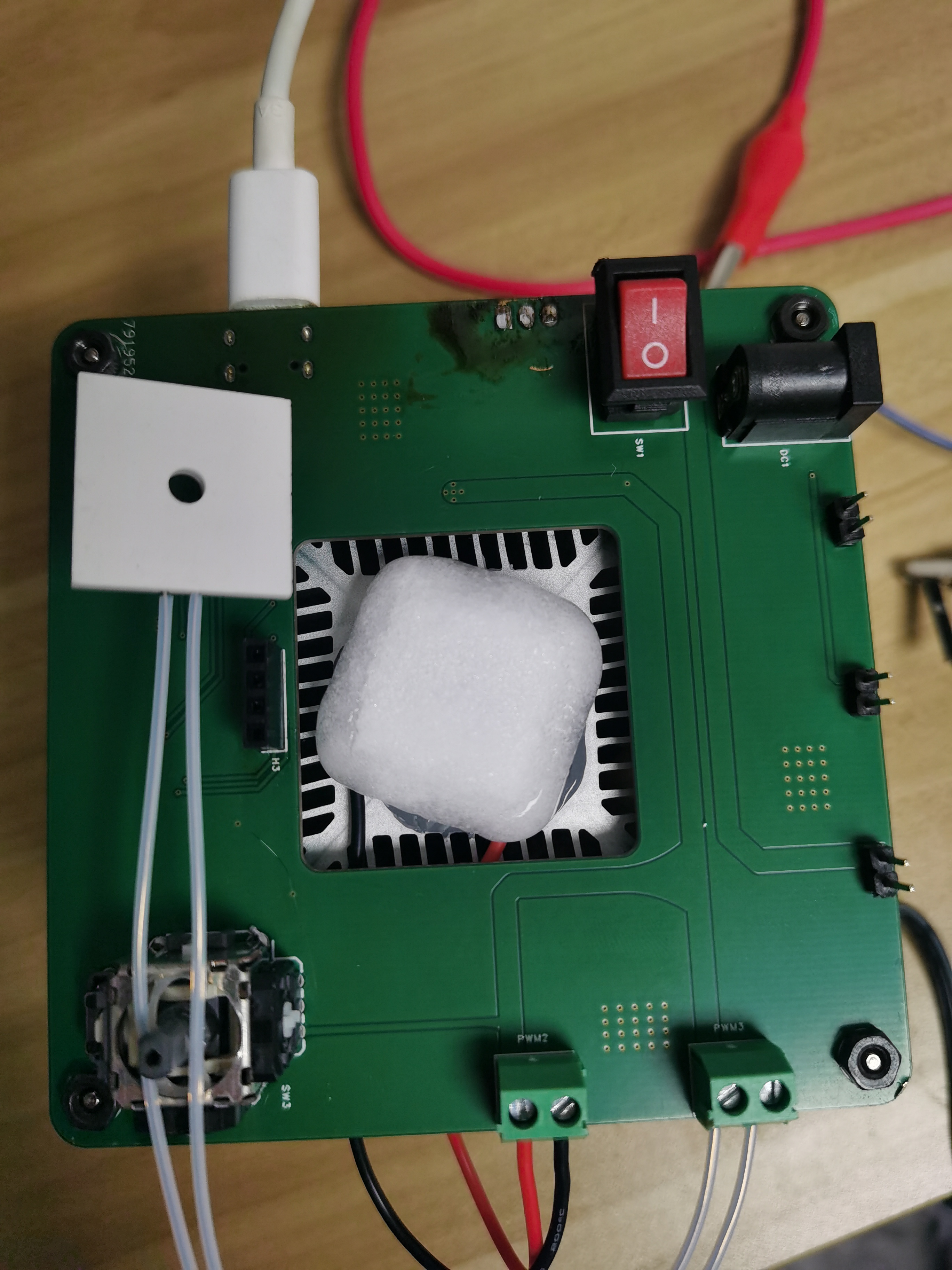
Mini PCR Instrument - Main Control Board
The main control circuit board of a mini PCR instrument (DIY purpose)
Note:
This is the main control circuit board of a simple PCR thermal cycler (╹△╹). I tried to DIY a simple PCR thermal cycler. (PCR: Polymerase Chain Reaction)
Functions:
1. DC plug input 5V 2A power (can also be powered directly using TYPE-C port 5V 2A, but remember not to plug in both at the same time!);
2. Semiconductor cooling chip interface: "PWM1" (power can be adjusted using PWM method);
3. High-temperature ceramic heating element interface: "PWM2" (power can be adjusted using PWM method);
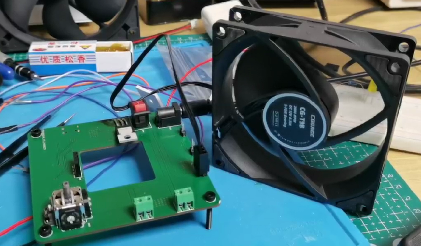
4. Cooling fan interface: "PWM3" (power can be adjusted using PWM method);
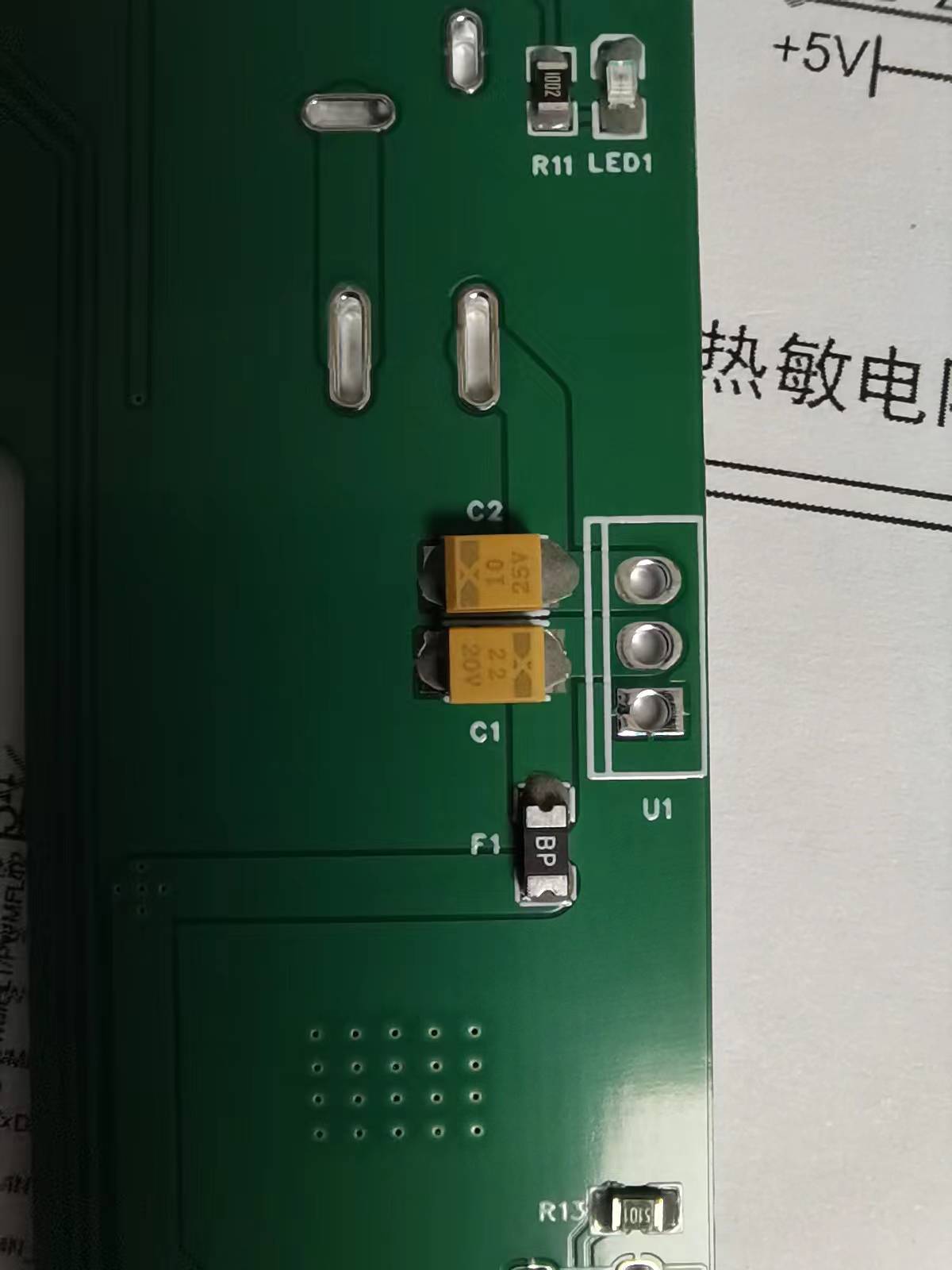
5. NTC thermistor and interface;
6. IIC protocol screen interface;
7. Five-way remote sensing input button (very cool);
8. Mounting hole size adapted to common CPU heatsinks (80mm x 80mm);
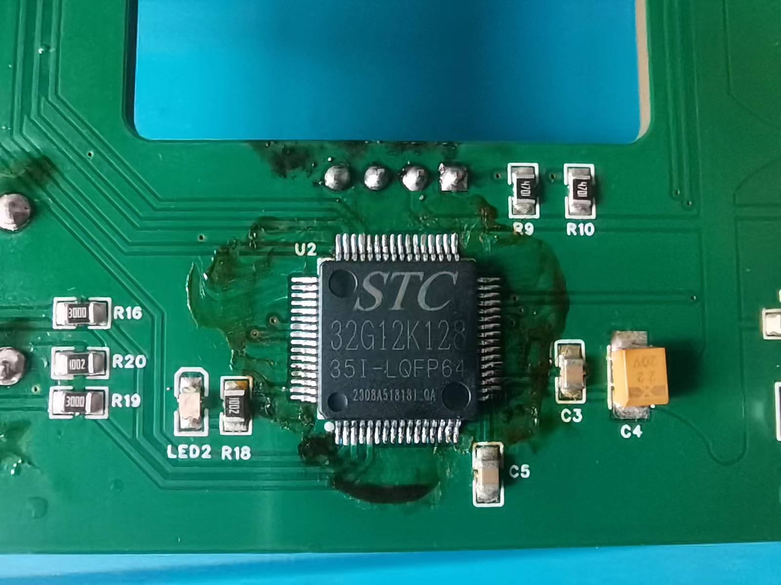
9. Super cheap and durable main control chip "STC32G12K128" (24MHZ, 12KB RAM, 128KB ROM, no external crystal oscillator required, ..., purchased from official channels for 3 yuan per chip);
Some simple test screens:
Soldering:
Functional test:

Acknowledgements:
Thank you JLCPCB for the free sampling, which gave me the courage to try and fail. Thank you~
PDF_Mini PCR Instrument - Main Control Board.zip
Altium Mini PCR Instrument - Main Control Board.zip
PADS Mini PCR Instrument - Main Control Board.zip
BOM_Mini PCR Instrument - Main Control Board.xlsx
93401
electronic


 京公网安备 11010802033920号

 2200BGG100J23KA


