Video Link:
Bilibili Video -- Function Demonstration and
Project Introduction
This project is a wireless measurement and control recorder based on the ESP32-S3 module, suitable for testing and measurement, data acquisition, industrial control, education, and other fields. It features 8-channel ADC analog voltage acquisition (0~3.3V) for acquiring real-time voltage signals from sensors such as light intensity sensors and thermistor sensors, as well as analog voltage output signals; 4-channel digital input for monitoring switch signals; and 4-channel digital output for controlling relay and buzzer module on/off switch signals. In addition, the project hardware includes a built-in DHT011 sensor for real-time monitoring of ambient temperature and humidity changes, and a MICRO SD card for local storage of real-time acquired data. Finally, it reserves space for a boot button (IO0), a debug serial port, and five GPIOs for future expansion to implement more functions.
Project Functions
: 1. Eight-channel ADC analog single-ended voltage acquisition;
2. Four-channel DI digital input signal acquisition;
3. Four-channel DO digital output signal acquisition;
4. Built-in DHT011 temperature and humidity sensor for temperature and humidity data acquisition;
5. Reserved 5 GPIO ports and serial port debugging pin header wiring;
6. Real-time acquired data accessed via wireless network page;
7. Real-time data transmission via USB port and monitoring via LabVIEW software;
Screenshots of real-time ADC, DI, DO, and temperature and humidity data from the wireless monitoring recorder accessed via wireless network are shown below:
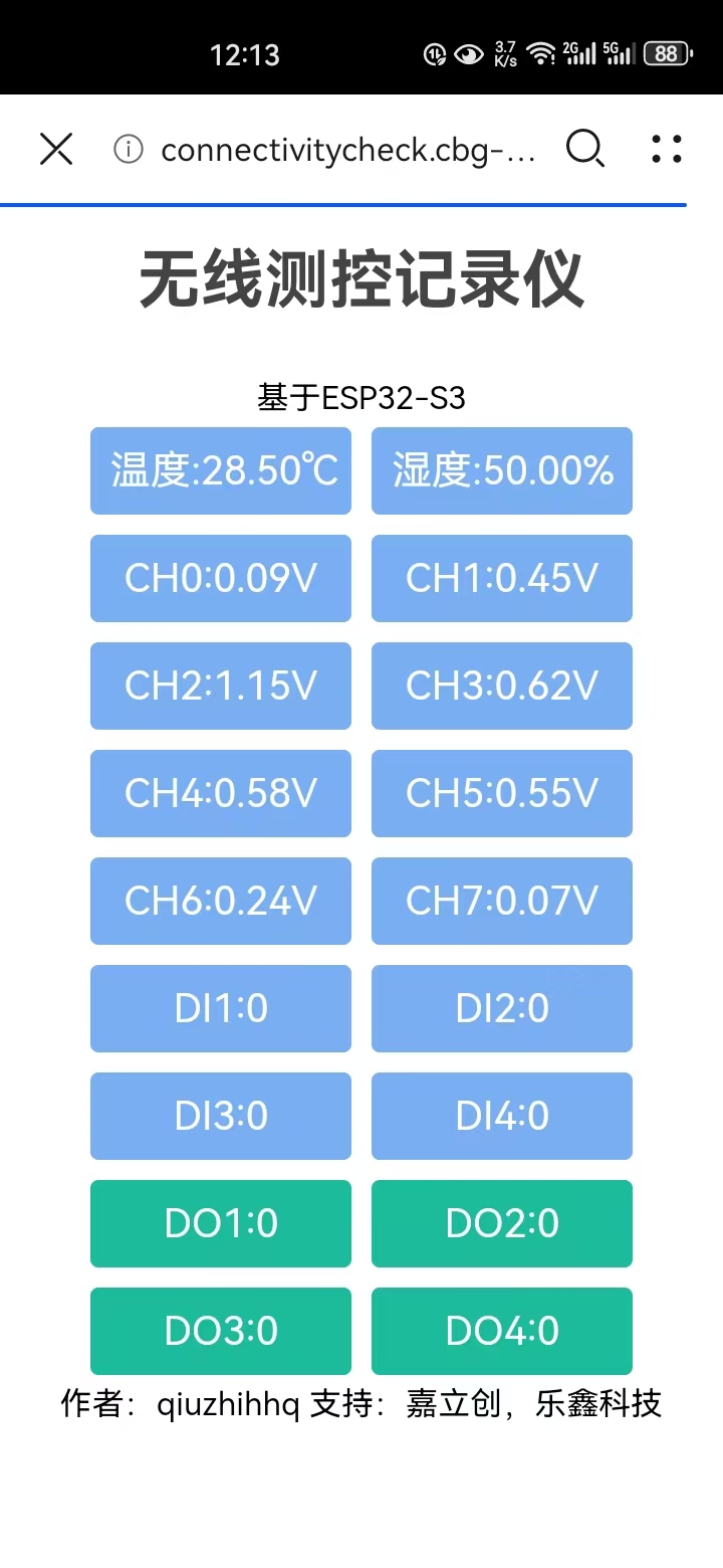
This design establishes an AP hotspot using ESP32-S3, then forces a portal jump to the monitoring interface. After connecting to the wireless monitoring recorder, it automatically jumps to the real-time data monitoring webpage. Alternatively, after connecting to the hotspot wireless network emitted by ESP32, the data monitoring webpage interface can be accessed manually by entering 192.168.4.1 in the browser.
This wireless controller can switch between modes in the lower left corner to determine whether to record data to the SD card. When in Wi-Fi mode, the collected data will be recorded to the SD card. When in USB flash drive mode, writing monitoring data to the SD card will stop, making it convenient to remove the SD card and read the saved data.
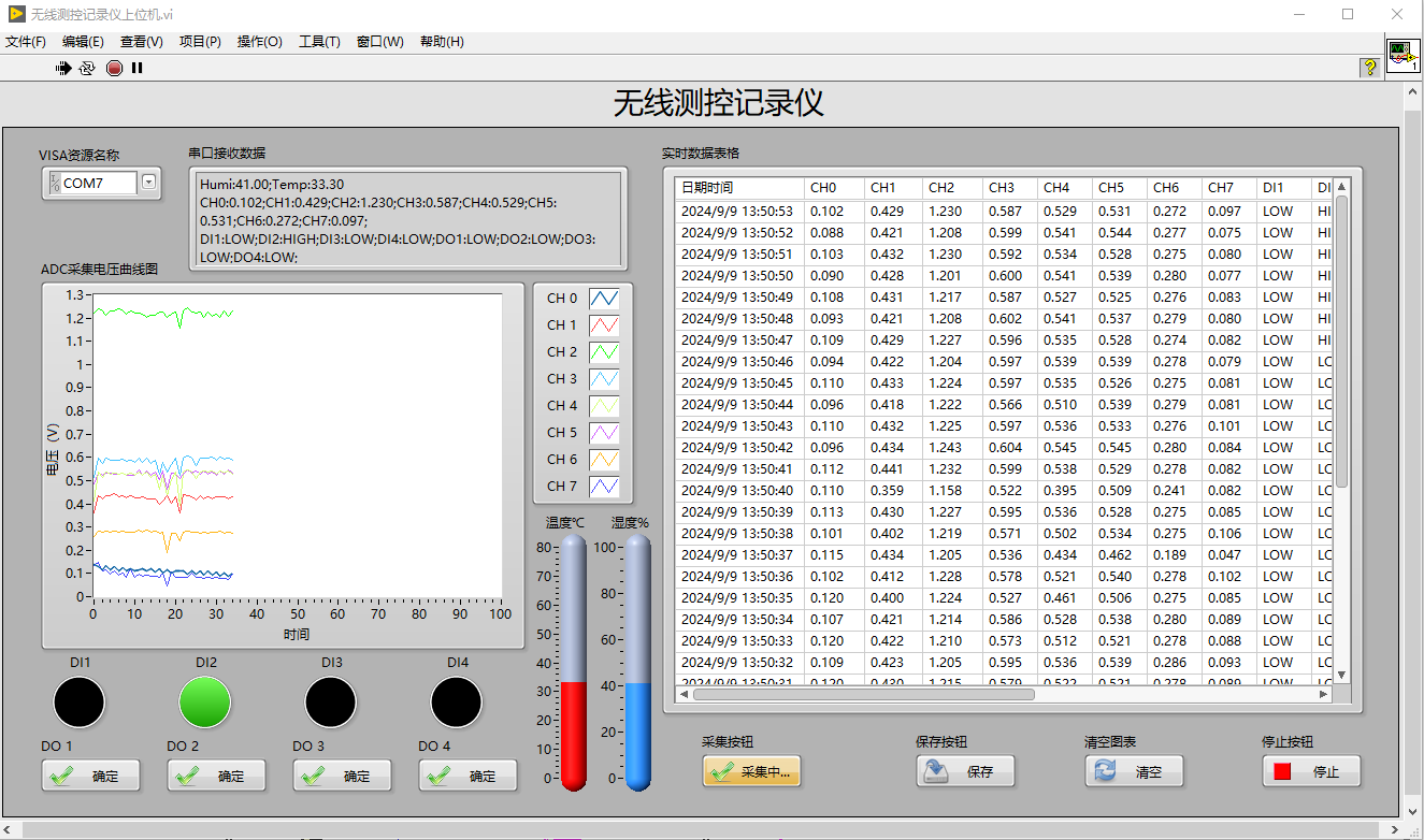
In addition, the author also developed a LabVIEW data monitoring system software to support the wireless measurement and control recorder. Screenshots of the software operation are shown below:
Project Parameters
* This design uses the ESP32-S3-WROOM-1-N8R8 module as the main controller, which can establish a wireless hotspot to send the collected monitoring data to a webpage for viewing;
* This design comes with a built-in DHT011 temperature and humidity sensor, which can collect and monitor temperature and humidity in real time;
* This design supports eight channels of analog voltage acquisition and eight channels of digital input/output acquisition and control, suitable for IoT data acquisition and control;
* This design uses an SD card to store the collected monitoring data and is equipped with a toggle switch and indicator lights to switch whether to save data to the SD card;
* This design is accompanied by a LabVIEW host computer that can collect complete monitoring data in real time and save the data to the computer;
Principle Analysis (Hardware Description)
This project consists of the following parts:
1. PCB Schematic Design:
Design the ESP32 peripheral circuit according to the official documentation, and then add ADC, DI, DO circuits, SD card, DHT011, etc., according to the product design functions. Detailed schematics and each part are shown in the design board1 - schematic diagram.
(Components can be directly generated into a BOM on LCSC EDA software and then redirected to the LCSC online store to place an order.)
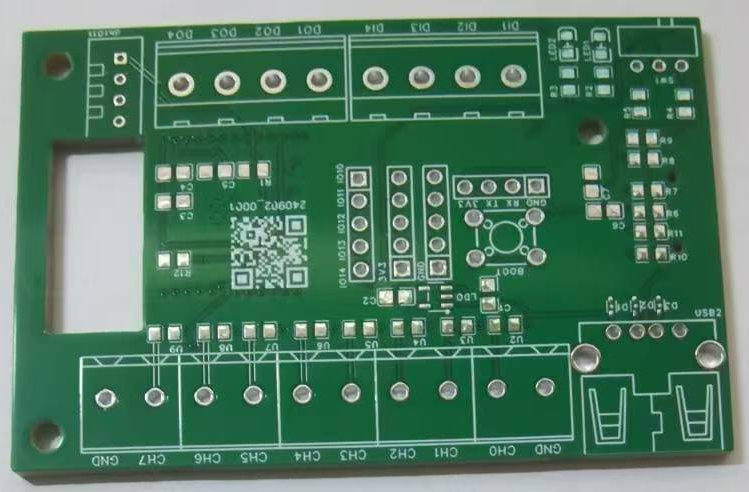
2. PCB LAYOUT Design:
The layout uses a four-layer board design. After the design is completed, check that the DRC is error-free and then directly place a free sample at JLCSC. The actual PCB design is shown below:
Front:
Back:
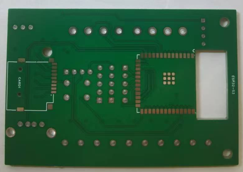
(The PCB can be directly ordered from JLCSC PCB through LCSC EDA.)
3. 3D Shell Design:
After the PCB layout is completed, the 3D shell can be designed on this basis. The 3D model can be previewed in real time on LCSC EDA and can be directly 3D printed at JLCSC. The actual product is shown below:

(The 3D shell can be directly ordered from JLCSC 3D Printing through LCSC EDA.)
4. Panel Design:
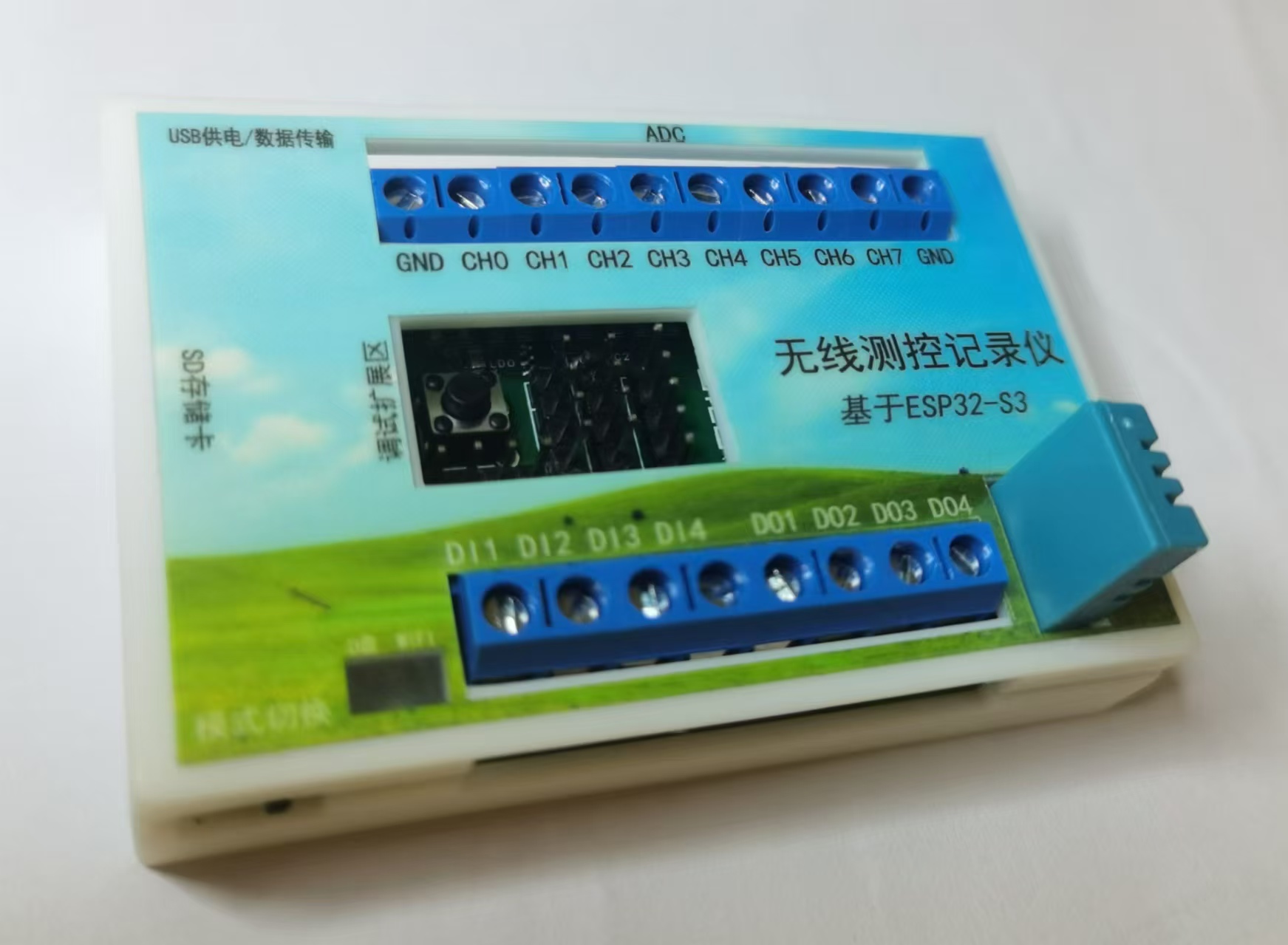
LCSC EDA can also be used to design panel stickers for instruments and meters. The original panel design is available in Design Drawing - Panel_1 - Panel. The actual product image is shown below (3D shell surface sticker):

(The panel can be ordered directly from LCSC EDA to the LCSC online store, and components can be linked for shipping to save on shipping costs.)
PS: Thanks to JLCSC for providing PCB prototyping coupons, 3D printing coupons, and component coupons~
Software Code:
This project uses Arduino as the lower-level hardware programming and LabVIEW as the upper-level monitoring software programming.
The source code for both the upper and lower-level software is attached (ino and vi files);
pressing and holding the BOOT button for more than 5 seconds will force a restart of the wireless monitoring recorder;
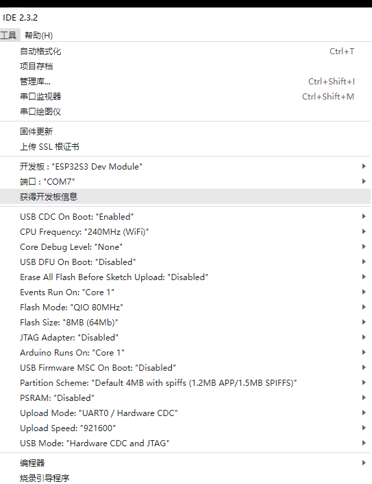
it is important to note the Arduino settings for the development board. Only by correctly configuring and enabling USB CDC can the ESP32 S3's built-in USB port be used for programming and data communication. The following screenshots are provided for reference: Notes:
Some
issues encountered during the completion of this project are recorded below:
When soldering the ESP32 S3 module, align and solder the four corners first, then use solder paste and a hot air gun to solder them sequentially;
During Arduino programming, the serial port may be recognized, but programming may fail with a "cannot connect to serial port" message. In this case, open the computer's Device Manager, right-click and uninstall the corresponding hardware serial port, then re-plug and re-plug the USB.
LabVIEW host computer recognition of serial port data requires the NI-VISA module to be installed beforehand. Additionally, version 2018 or later is required to open vi files correctly;
If the computer cannot recognize the USB, resulting in programming failure, try pressing the BOOT button and then re-plugging the USB. This will allow the computer to recognize port COM7 again;
It has been found that the lack of a pull-down resistor on the ADC sampling port causes random voltage on the unconnected ADC acquisition signal line, which will be fixed in a later version.
Assembly Process:
1. First, solder the surface-mount resistors on the front, then solder the pin headers and terminals, and finally solder the SD card slot and ESP32-S3 module on the back.
2. After soldering, place the module into the bottom 3D housing. Note that the 3D housing has a small margin around the edges, so you need to insert it slowly and completely.
3. The screw posts on the top 3D housing are too long; you can shorten them with needle-nose pliers. Then, apply the panel sticker to the top 3D housing. Pass the DHT011 sensor and ADC, DI, and DO terminals through the panel.
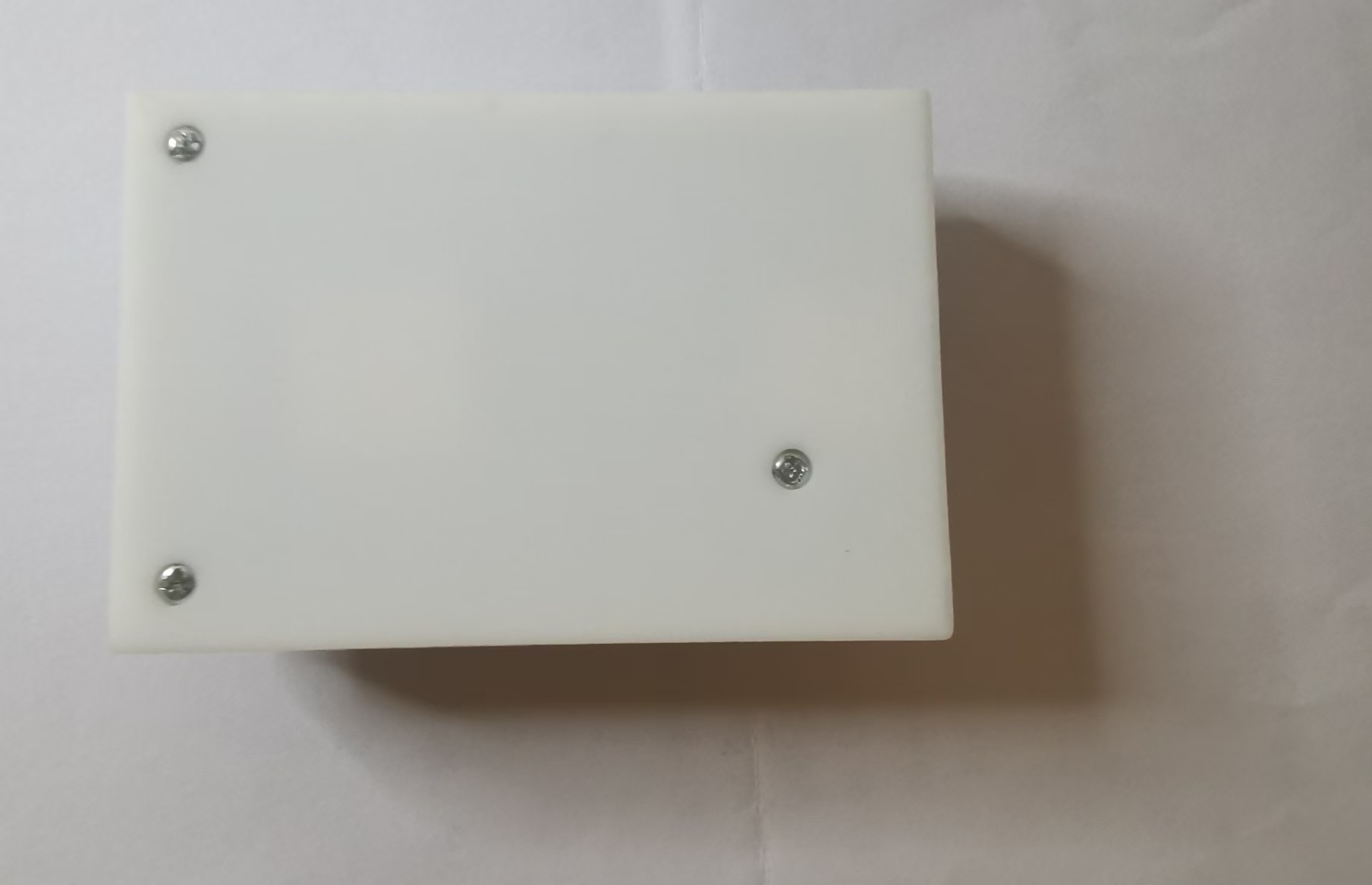
4. After the top and bottom housings are in place, flip the module over and tighten the three bottom screws in sequence. Complete assembly photos:
Front view: Side view: Back view:

Finally, I would like to thank JLCPCB and Espressif Systems for their support, which inspired, implemented, and completed this project.


 京公网安备 11010802033920号

 E14/3.5/5-3C94-A63-E


