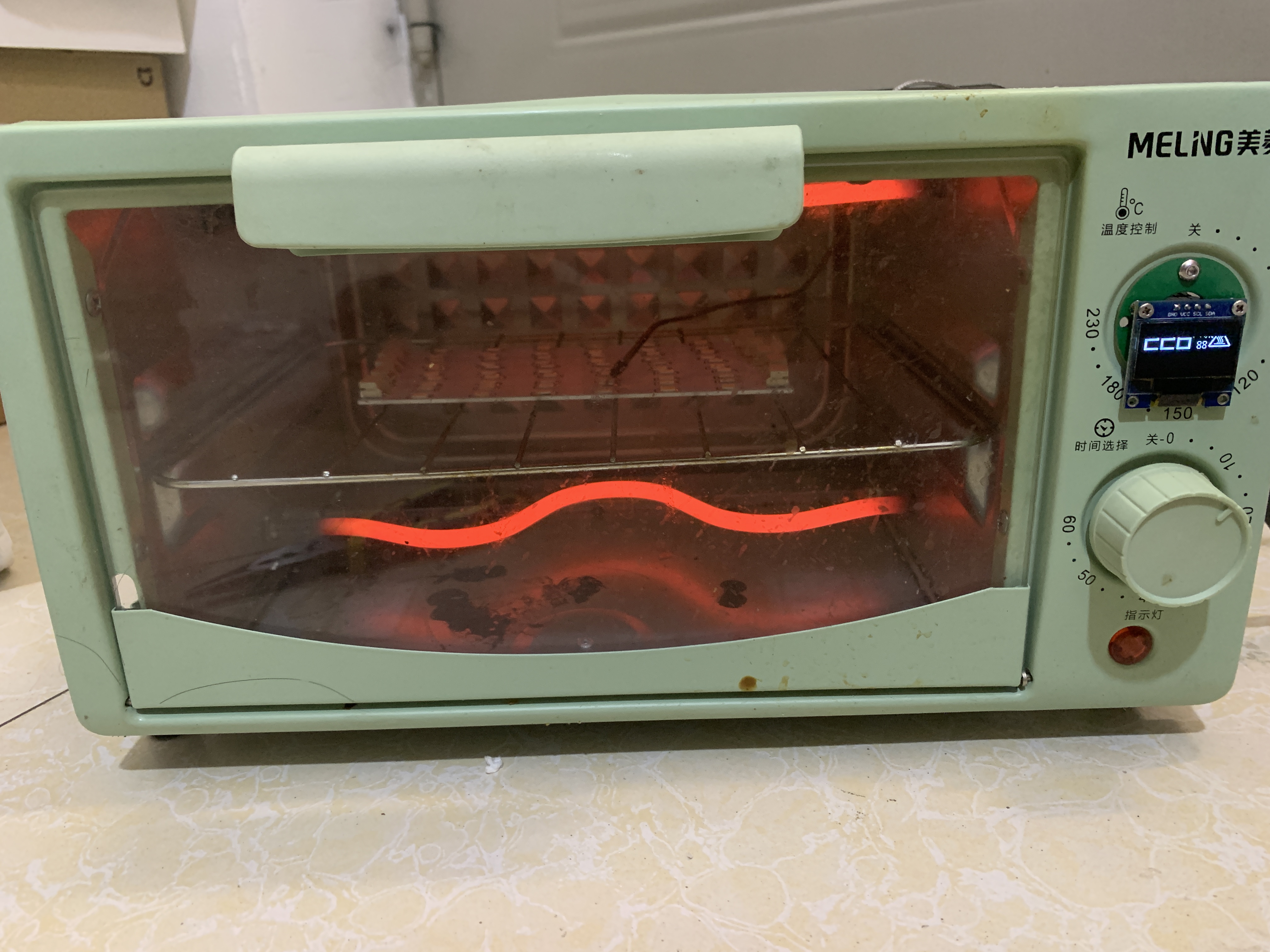
I've replicated the "Super Simple ESP32 Heating Platform V2"
(https://oshwhub.com/false0/esp32-jia-re-tai_copy) from this site, making some modifications based on my own inventory.
Project address: https://github.com/652626737/kk-heater-reflow-soldering
PDF_ESP32 Reflow Oven - Control Board V2.zip
Altium_ESP32 Reflow Oven - Control Board V2.zip
PADS_ESP32 Reflow Oven - Control Board V2.zip
BOM_ESP32 Reflow Oven - Control Board V2.xlsx
94305
[Verified] STM32F103C8T6 Minimum System Board
This is a homemade small board for the STM32F103C8T6. It's small in size and can be fired on a single-sided iron plate in one go. The pinout is a 1:1 replica of the common small blue boards on the market.
![WeChat image_20240611195146.jpg]

A homemade STM32F103C8T6 mini-board. All components are arranged on only one side of the board, allowing for single-sided baking. All pins are brought out one-to-one with common small blue boards on the market, but because it is too wide, it cannot be inserted into a breadboard QAQ.
The board uses a CH340C serial port to USB chip (you can also replace it with CH340N or other models to save space). It also has indicator lights to make it easy to check the transmission status. In addition to the onboard peripherals, there is a button on PA0 (WKUP) and an LED on PC12.
The board uses ST-Link as the primary download method and provides relevant interfaces, but also includes a BOOT button, theoretically supporting serial port program download (the author has not verified this due to infrequent use).
***Note that the LED resistor values in the schematic are for reference only. I personally believe the brightness is very low; please determine the specific resistance value according to your brightness requirements. Around 1KΩ is recommended. Furthermore, the BOM (Bill of Materials) is only for reference; exporting the BOM for ordering is not recommended.***
The board was designed by myself. I welcome any criticism and suggestions for improvement
! [WeChat image_20240611194738.jpg]

The 1.3-inch OLED screen in the image is from another project: https://oshwhub.com/maker114/1-3-cun-oled
PDF_【Verified】STM32F103C8T6 Minimum System Board.zip
Altium_【Verified】STM32F103C8T6 Minimum System Board.zip
PADS_【Verified】STM32F103C8T6 Minimum System Board.zip
BOM_【Verified】STM32F103C8T6 Minimum System Board.xlsx
94306
ESP humidifier
The humidifier uses a 555 motor and is controlled by an ESP-12S controller.
I. Humidifier Design
The humidifier uses an NE555 timer to generate a 108kHz square wave to drive the spray nozzles. Direct drive voltage is too low, so a boost circuit is used to increase the voltage. An ESP-12S control chip is added to enable IoT control of the humidifier. An AHT20 temperature and humidity sensor is used to detect ambient temperature and humidity.
II. Boost Circuit The
boost circuit consists of two parts:
a 12V boost circuit
and a MT3608 boost chip. The 12V boost circuit ensures the minimum operating voltage for the spray nozzles.
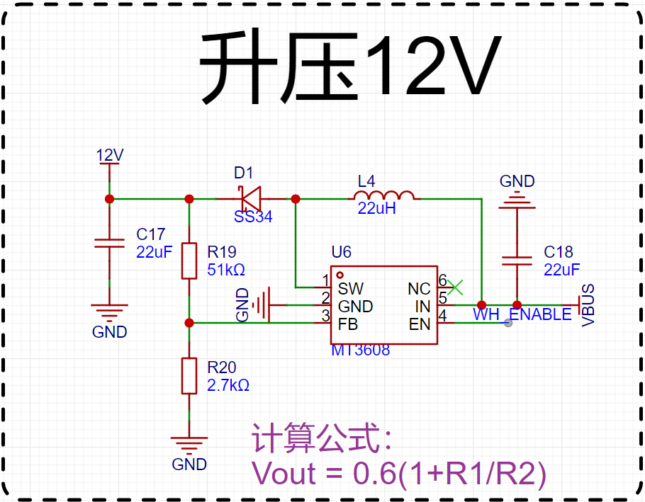
The output voltage depends on the ratio of two resistors, calculated according to the formula in the chip's datasheet. These two resistors were adjusted based on my existing resistors.
The boost circuit
is shown in the diagram below. The switching transistor controls the inductor's energy storage and release, resulting in a higher output voltage than the input voltage.

III. Frequency Generation Circuit A
555 timer is used to generate a 108kHz frequency. The output frequency calculation is shown in the diagram. Since I used existing components, and considering the accuracy of the capacitors, the actual output frequency needs to be tested to ensure it matches correctly.

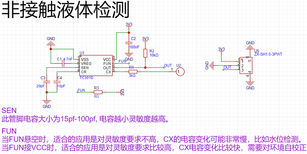
IV. Non-contact Liquid Detection:
The TC301D is used for non-contact liquid detection. Pay attention to the PCB layout; specific details can be found in the datasheet.
V. Shortcomings and Optimizations:
Because many components are readily available, the circuit power supply is insufficient. The inductors and capacitors in the boost circuit could be replaced with smaller ones. Non-contact liquid detection has not yet been verified.
IMG_6458.MP4
BOM_ESP Humidifier.xlsx
94308
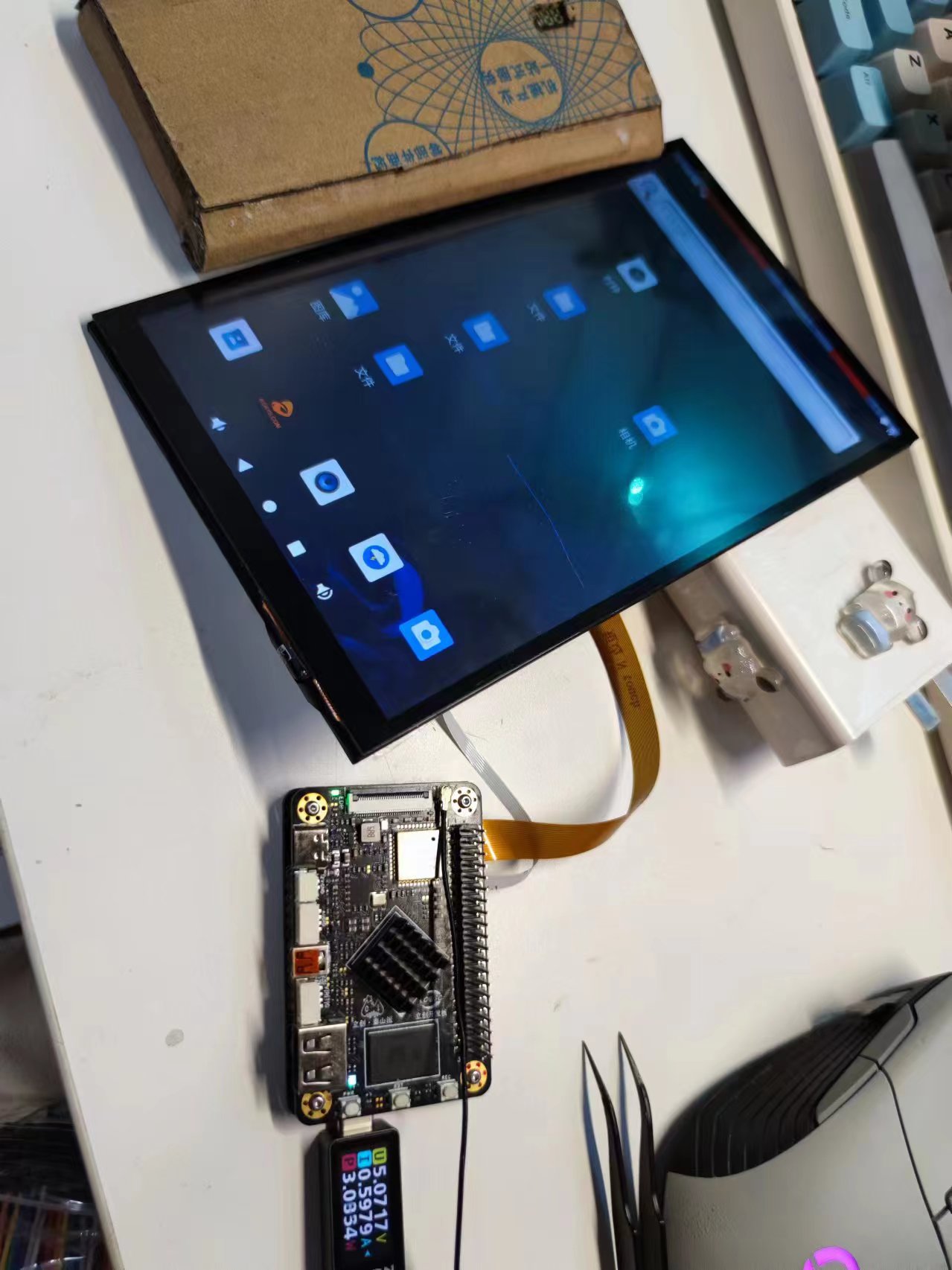
Smart small mobile phone
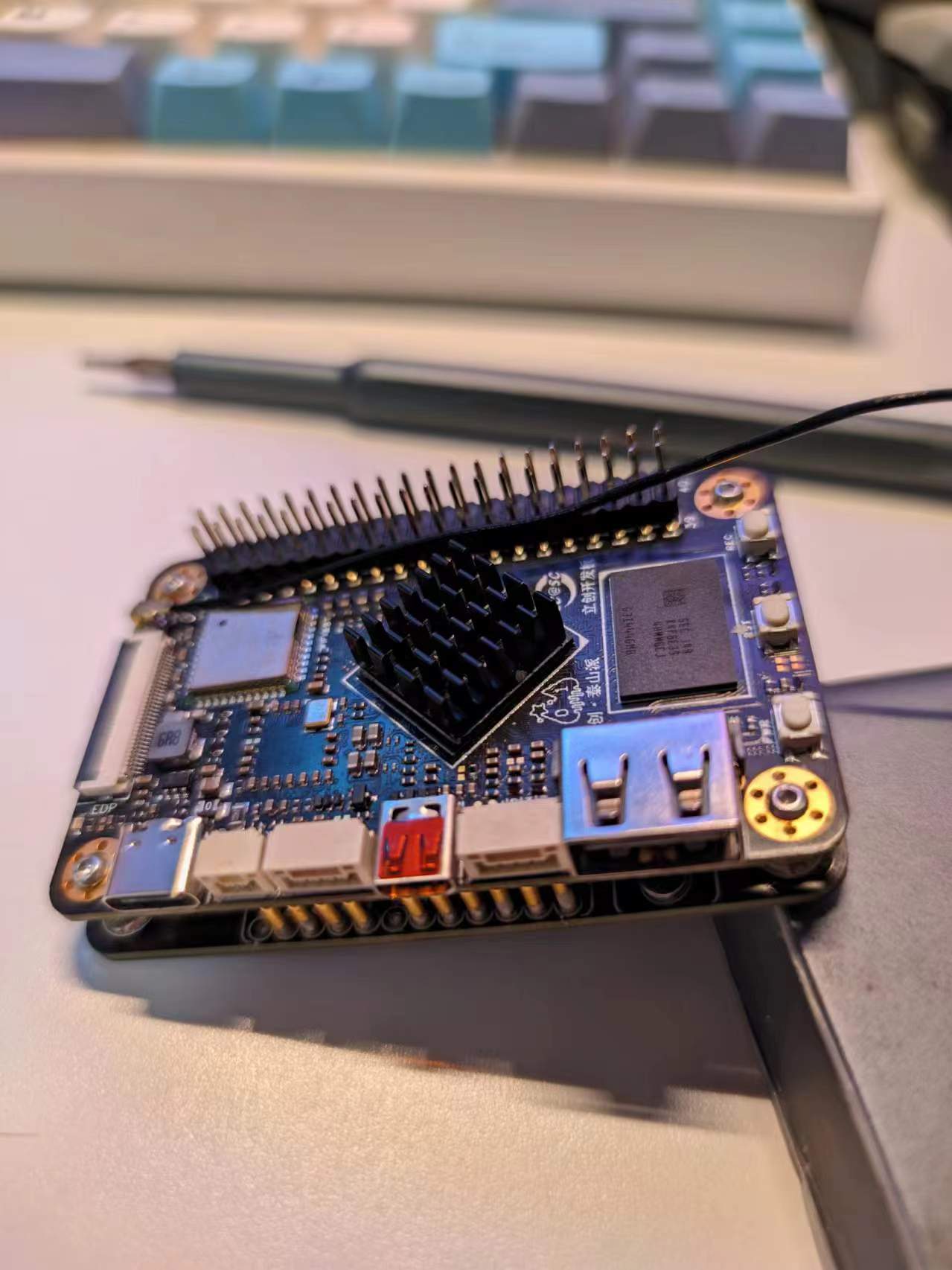
This is a small smart phone expansion board based on the Taishanpai platform. It features onboard USB-to-TTL conversion, battery charging, 5V-to-12V power supply, and automatic battery/USB switching circuitry. It also adapts the pin order of the Taishanpai's built-in MIPI and touch interfaces to a 3.1-inch touchscreen display.
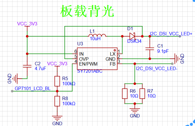
The IIC-to-PWM control of the screen backlight
extends from the touch IIC pin of the Taishanpai device, using a GP7101-F1K-L1H1-SW chip.
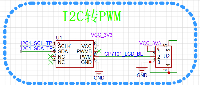
A SY7201ABC constant current source chip then converts the PWM signal into a constant current to drive the screen backlight.
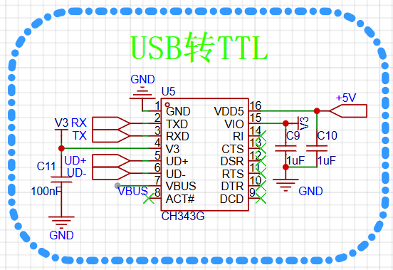
The Taishanpai device also has TTL contacts, enabling direct data communication with the computer via a USB-to-TTL converter.
The lithium battery management circuit
uses an IP5407 chip to build a lithium battery charging circuit,
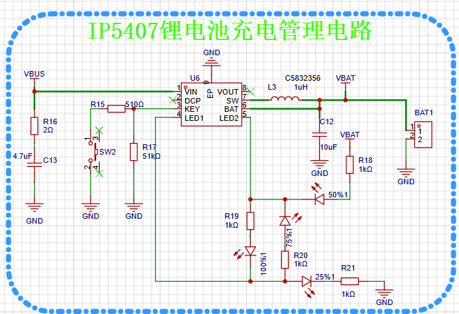
converting 5V USB voltage or 4.2V battery voltage to 12V to power the Taishanpai device.
A BOOST boost circuit using an MT3608 chip provides the 12V output. (Actual

product demonstration shown. )


PDF_Smartphone.zip
Altium_Smartphone.zip
PADS_Smart Mini Phone.zip
BOM_Smart Small Phone.xlsx
94309
electronic


 京公网安备 11010802033920号

 M3E61ZQX


