1000V internal capacitor discharge

PDF_Electrical Pen (Verified).zip
Altium_Electrical Pen (Verified).zip
PADS_Electrical Pen (Verified).zip
BOM_Electrical Pen (Verified).xlsx
92138
DPAD rotary keypad-USB-CH582F
The DPAD series keypad is an optimization of another engineered rotary keypad, including the use of the CH582F with fewer pins, better solderable low-profile LEDs, and an added pull-down resistor for the CC pin.
## I. Introduction
The DPAD series keypad is an optimization of the rotary keypad in another project, including the use of the CH582F with fewer pins, easier-to-solder base LEDs, and the addition of a pull-down resistor for the CC pin.
## II. Notes
Open source hardware. Software and host computer are not open source. An unlock code is required for normal use.
## III. Function Description
1. Buttons and knobs support customizable buttons, multimedia, touch mouse, Dial, and macros.
2. Customizable lighting effects.
3. Supports configuration after installing the host computer on Windows. [Web configuration will take some time.]
## IV. Installation Tutorial
1. Please refer to the other project for installation. The first installation requires WCHISPTOOL; subsequent updates can be made through the host computer.
Reference project link: DPAD-Rotary Keyboard-Keypad-CH582M - LCSC Open Source Hardware Platform (oshwhub.com)
2. Firmware (.bin file) needs to be downloaded from the attachment on this page.
3. For host computer software and firmware, please download the latest version from the reference project.
## V. Commercial Use Instructions:
Commercial use is supported as is or with modifications. Free unlock codes are provided for a small number (5 codes). A fee will be charged for additional codes beyond that.
Firmware-6K1E-CH5812F.bin
PDF_DPAD keypad-USB-CH582F.zip
Altium_DPAD rotary keypad-USB-CH582F.zip
PADS_DPAD rotary keypad-USB-CH582F.zip
BOM_DPAD rotary keypad-USB-CH582F.xlsx
92139
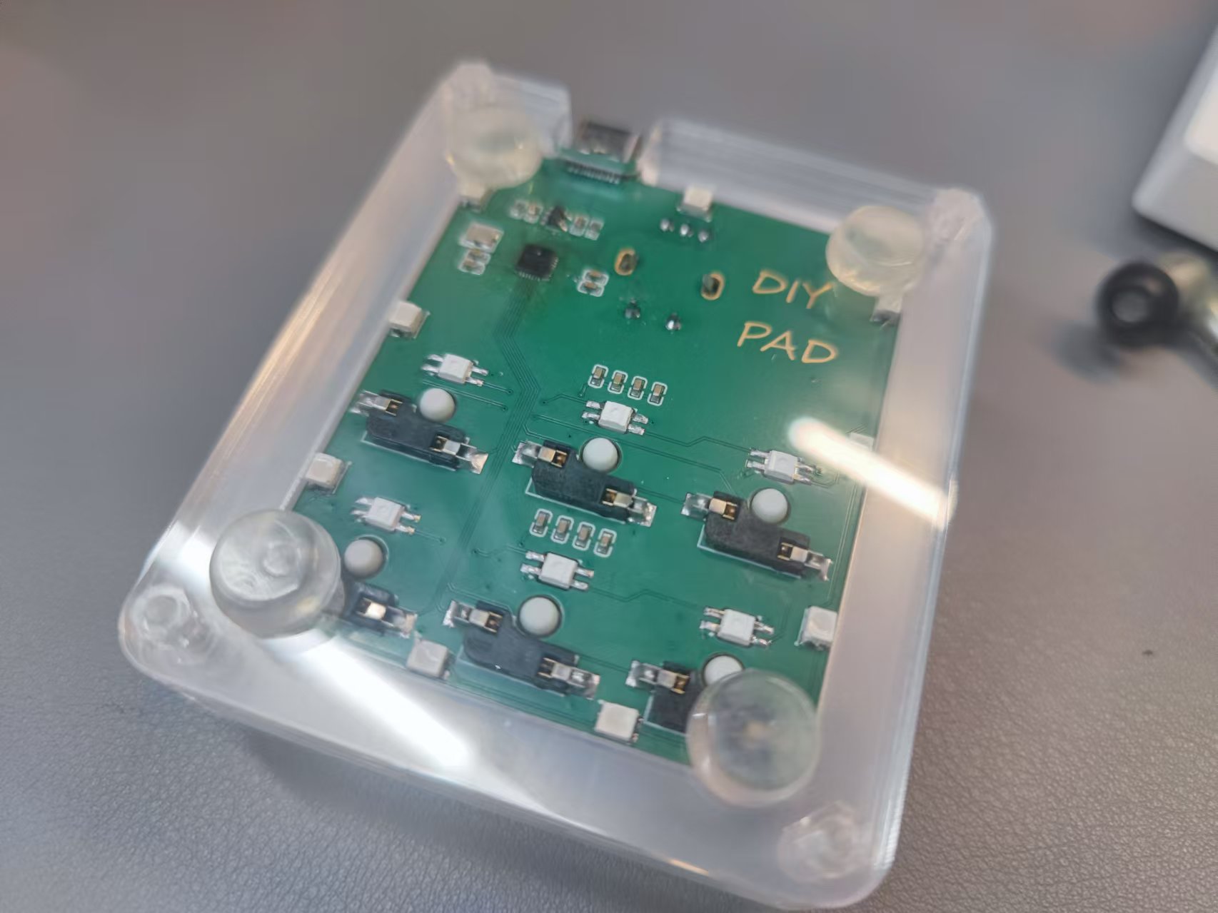
Lonely Rock Glowing Bookmark Pendant Light DIY Peripheral Capacitor Switch
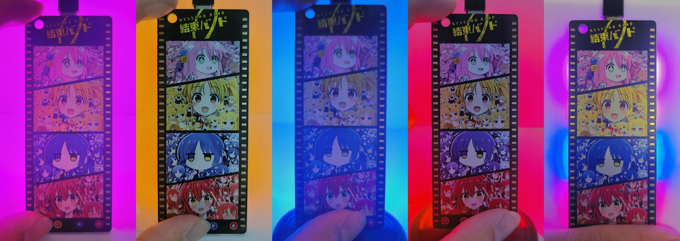
Lonely Rock 'n' Roll PCB Illuminated Bookmark, Colorful Silkscreen Pendant, DIY Merchandise. LEDs are controlled by touch. The four images on the silkscreen are from the internet and are not original.
The overall design
mimics the effect of film reel, with immersion gold filling and solder mask openings on both sides. Another approach is slotting, but I didn't try that (actually, I ran out of color silkscreen printing coupons).
The silkscreen printing on both sides was drawn in Photoshop. The four images of "Lonely Rock" are from the internet; I couldn't find the artist's information, but I'd like to express my gratitude here. (This open-source project is non-profit; please contact me if there are any copyright infringements.) The first four
images show
the PCB with no obstruction and individual LEDs lit; the fifth image shows the PCB with obstruction (A4 paper) and all LEDs lit.
Implementation principle
: Touch buttons: A capacitive touch switch solution is used, with the touch IC being TTP223E-BA6.
LED on/off: An NMOS is used, with the gate connected to the touch IC's output, and the source and drain connected to the LED and GND.
Documentation
: Project with lighting: Version with components; it is recommended to carefully read the text description on the schematic before replicating.
Project without lighting: Version without components, for design reference only. Attached are PCB bookmarks - front.png and PCB bookmarks - back.png: These are replicas
of the original silkscreen images exported from Photoshop. Note that the PCB uses a color silkscreen printing process. When ordering, it is recommended to first select immersion gold and white solder mask, and then select color silkscreen printing. The price is 50 yuan for 5 pieces. Using a 50 yuan color silkscreen printing coupon will allow for free board making. The LEDs were purchased from the Taobao store Youxin Electronics, with the keyword "0805 LED high brightness". For aesthetic and economic reasons, the component packages are generally small, requiring some patience for beginners when soldering. Another recommended option for the lighting is ceramic filament; you can try it if you are interested.
PCB Bookmark - Front View.png
PCB bookmark - reverse side.png
PDF_Lonely Rock Glowing Bookmark Pendant Light DIY Peripheral Capacitive Switch.zip
Altium_Lonely Rock Glowing Bookmark Pendant Light DIY Peripheral Capacitive Switch.zip
PADS_Lonely Rock Glowing Bookmark Pendant Light DIY Peripheral Capacitive Switch.zip
BOM_Lonely Rock Glowing Bookmark Pendant Light DIY Peripheral Capacitive Switch.xlsx
92140
STM32 Extended Version
An STM32 expansion board designed for a school electronics competition. It has an OLED interface, a remote sensing interface, an OpenMV interface, and an unverified voice module.
Video demonstration: See attachment below (simple curve based on remote sensing changes on an OLED screen).
Project introduction:
The school's electrical engineering competition will most likely utilize remote sensing and OLED displays. Based on this, some peripherals were added for my future use.
Please feel free to point out any shortcomings.
3d40b231fe0b5bd65bb70963afdd7f16.mp4
PDF_STM32 Extended Version.zip
Altium_STM32 Extended Version.zip
PADS_STM32 Extended Version.zip
BOM_STM32 Extended Version.xlsx
92141
STM32F103C8T6 expansion board
The STM32F103C8T6 minimum system expansion board supports 5~35 inputs and output voltage of 5V 5A.
This STM32F103C8T6 minimum system expansion board is designed for learning STM32F103C8T6 microcontrollers. It features a wide input voltage range of 6~35V and a maximum output of 5V5A, sufficient for most applications.
The board uses the XL4005 step-down chip, ensuring stable output voltage and low ripple. It supports 4~5 large servos, with inputs via XT60 or terminal blocks, and includes an 8-pin LCD interface. **
Important Note:** The feedback resistor in the step-down circuit should ideally have 1% accuracy; otherwise, the output voltage deviation will be significant.
Future development may consider adding a motor drive module, a 2.4GHz module, a Bluetooth module, and an MPU6050.
PDF_stm32f103c8t6 expansion board.zip
Altium_stm32f103c8t6 expansion board.zip
PADS_stm32f103c8t6 expansion board.zip
BOM_stm32f103c8t6 expansion board.xlsx
92142
Electronic Sticky Notes_Memo_8223867A (V1.0 verified by prototyping)
It pushes memos via server and features a buzzer for timed reminders, such as holiday reminders or work reminders.
It also has a TF card slot, allowing it to be used as a mini NAS for LAN file transfer and temporary storage.
Independent power management allows it to function as a power bank for emergency power to mobile phones and other devices.
Figure V1.0 has the following problems:
9.10
The power supply schematic IP5306 GND is not connected, the SY8089 enable pin is not supplied with voltage, and the detection resistor is not properly connected; 9.10 After the jumper wire is connected, there is a 3.3V power output;
The LED on pin 33 is not lit (it is triggered by a low level, and is lit by default; it can be used as a power indicator).
Inspection suspected a cold solder joint on the CH340X. After multiple reworks and overcoming the difficulty of solder bridging, it was decided to resolutely avoid using microchips in the future (the pins are too dense, making manual work extremely difficult). On
September 11th
, the CH340 was still not recognized upon power-up. Upon inspection, no 3.3V power was found. The power supply buzzer was frequently triggered
, leading to suspicion of a buzzer malfunction. The buzzer was removed, and the voltage was checked again, finding it fluctuating between 1.8V and 1.6V;
a short circuit was suspected, triggering the SY8089A1AAC protection (this was ruled out).
After a period of rest (approximately 3 hours), the SY8089A1AAC again output 3.3V. At
15:32,
with an external independent 3.3V power supply, the computer could recognize the CH340, proving it was working normally (it wasn't damaged by heat; I initially thought it was). At
15:35
, the voltage dropped further, fluctuating between 1.64V and 1.58V. Shorting
R23 to ground caused the LED to light up. Could the low voltage be due to an incorrect resistance ratio of the detection resistor?
September 15, 15:35:
Finally, a stable 3.3GHz connection was achieved (the cause was a faulty ground solder joint on the SY8089A1AAC; I thought that as long as the other pins were soldered correctly, leaving one unsoldered wouldn't matter). The computer could also recognize the CH340, and the software could be flashed.
September 16, 20:34:
Multiple download failures were discovered. Upon inspection, an RX and TX connection error was found. After correcting the error with jumper wires, a blue screen appeared on every download attempt.
Apparently, this was because the CH340's storage space was relatively small, causing it to frequently request storage from the CPU. It seems a chip replacement is needed.
V1.1 rewiring improved the above issues. Software debugging will begin once the CH343P chip arrives.
Project Description:
A server-side push notification feature with a buzzer for timed reminders, such as holiday reminders or work-related reminders. It includes a TF card slot, allowing it to be used as a mini NAS for LAN file transfer and temporary storage.
PDF_Electronic Sticky Notes_Memos_8223867A (V1.0 Prototype Verified).zip
Altium_Electronic Sticky Notes_Memos_8223867A(V1.0 Prototype Verified).zip
PADS_Electronic Sticky Notes_Memos_8223867A (V1.0 Prototype Verified).zip
92143
TP5100-1S Lithium Battery Charger
TP5100 three-channel 1S lithium charger, 1A per channel. Type-C input.
Charging my model airplanes in the field is a bit of a hassle. Inexpensive wired chargers are unreliable and prone to overcharging. Dedicated model airplane chargers are overkill and bulky, so I decided to make my own.
I have batteries around 400mAh, so a 1A charging current is sufficient; current limiting is crucial. Most current charging ICs are designed for power banks, and 2.4A is considered low; this current is very damaging to small batteries.
So I tried several older products: TP4056, 5100, and IP5305.
The original Topmicro 4056 worked stably, but the input voltage was limited to 5V, and the 1A charging caused excessive heat and low efficiency; third-party ones were even worse.
The IP5305 might be a counterfeit, only providing 200mA current, and the hot-swapping power indicator was malfunctioning.
Ultimately, I used the TP5100, with a 5-15V input, Type-C interface, and 3 channels charging at 1A each. Full power requires 3A input; don't charge simultaneously if the power supply isn't powerful enough.
Almost all of them use surface-mount components, and you can solve the problem by buying a barbecue grill for a little over ten yuan.
lv_0_20240915112715.mp4
PDF_TP5100-1S Lithium Battery Charger.zip
Altium_TP5100-1S Lithium Battery Charger.zip
PADS_TP5100-1S Lithium Battery Charger.zip
BOM_TP5100-1S Lithium Battery Charger.xlsx
92144
51 Microcontroller Desktop Temperature Clock Development Board
The main controller uses an STC89C52RC, the sensors are DS1302 and DS18B20, and the display uses a two-digit common cathode LED display and an LCD1602.
Project Introduction:
This project is a desktop temperature clock development board based on the STC89C52RC, featuring humidity detection and time display functions. It can be used as a course design and practice project for microcontroller courses. The development board uses a 0805 package for easy use and rapid soldering on a heating table.
Project Functionality:
This humidity clock development board is based on the STC89C51/52 microcontroller. The front has three independently programmable buttons, and the back has a matrix button and running lights. It uses a 0.36-inch common cathode white digital tube driven by an SN74HC595PWR, providing good display quality.
Project Parameters:
This design uses an LCD1602 liquid crystal display, with the top row displaying the current date and time.
It selects a DS18B20 humidity sensor; the driver code is simple, and the driver circuit is easy to understand, making it suitable for beginners. This should meet general needs. For
soldering
, a heating table is recommended. Use 138°C low-temperature solder and maintain a constant temperature of 170°C on the heating table.
When soldering the Type-C port with a soldering iron, apply solder paste first, and then use a wooden toothpick to apply solder balls to the pads while the device is heated. After cleaning the pads, install the components.
Design flaws:
Hardware:
1. Lithium-ion battery charging chips and voltage regulator chips should be used to greatly extend battery life
. 2. To control costs, this project did not include a power-off timing battery like the DS1302
. 3. This project uses too many vias in the circuit connections.
Software:
1. This project's software does not use a timer; delay relies entirely on for loops, blocking MCU time
. 2. It is recommended to add three independent buttons to control the time
(very important). The MCU's TXD and RXD should be connected to the CH340 module using flying wires, written into the download file in the example code, and called in the main function to enable hot-start download.
51 Clock Development Board Attempting to Keep Time Despite Power Loss - Copy.zip
PDF_51 Microcontroller Desktop Temperature Clock Development Board.zip
Altium_51 Microcontroller Desktop Temperature Clock Development Board.zip
PADS_51 Microcontroller Desktop Temperature Clock Development Board.zip
BOM_51 Microcontroller Desktop Temperature Clock Development Board.xlsx
92145
ultra_rainfall_radar
Ultrasonic Rain Radar
Project Overview:
This project is an experimental prototype of an ultrasonic radar rainfall monitoring system based on ESP32, capable of monitoring rainfall over short distances (within 10m).
In the field of microcontroller-based environmental monitoring devices (such as temperature, humidity, brightness, wind speed, air pressure, and lightning distance), no examples of non-contact rainfall monitoring have been observed.
Based on ultrasonic ranging, this project conducted experiments on the reflection of ultrasonic waves from raindrops and the basic noise of ultrasonic wave reception, analyzed the echo changes in various environments, and determined a scheme to add a bandpass amplifier to the received reflected wave. For experimental convenience, a 40kHz ultrasonic frequency is used in this scheme. According to the principle of sound wave reflection, for tiny raindrops, a higher frequency should yield a larger reflected wave, thus improving sensitivity. In principle, the rainfall can be calculated based on the characteristics of the reflected wave, but this has not yet been achieved.
This project utilizes the Wi-Fi function of the ESP32 and adopts the MQTT protocol to send rainfall, temperature, and humidity information to a server, which can be pushed to mobile devices. The server is built on a Raspberry Pi using NodeRed, with PeanutShell used for intranet penetration.
The hardware of this project uses an ESP32WROOM module, a 1.8" TFT color screen, a rotary encoder, a DHT temperature and humidity sensor, and an RCWL-9610 ultrasonic ranging chip and an operational amplifier. The power supply is TYPE-C5V.
Software development
is conducted using the ARDUINO IDE platform.
After power-on, the display, temperature and humidity sensor, encoder, and ultrasonic wave generator and receiver are initialized. A second interrupt is then enabled, and a start pulse is issued in its service routine, generating eight 40kHz ultrasonic pulses. These pulses are emitted by the ultrasonic head, and the reflected waves are received, amplified by multiple bandpass amplifiers, and detected. Then, an analog-to-digital converter is initiated to read the envelope value and display the echo signal on the screen. The sampling width is 12 bits, the rate is 3.4 ksps, the horizontal axis of the curve is 8M, and the vertical axis is the echo intensity (not calibrated).
The rainfall detection logic is as follows:
1. If the echo increases and persists for a period of time, such as 30 seconds, it is determined to be rainfall.
2. Rainfall intensity is used to determine whether it is heavy, moderate, or light.
The calibration of rainfall amount requires the relationship between ultrasonic echo and rainfall, which has not yet been implemented.
Regarding sensitivity, this solution is not sensitive enough for "drizzle." The following measures can be taken to improve it: a) Increase the frequency, such as 1MHz~10MHz, based on the characteristics of ultrasonic waves. b) Increase the transmission power. c) Add a conical "horn" to the ultrasonic head.
Software code
/Ultrasonic Rainfall Radar V.1.0 20240916 Zhang Yu 18566289792
Color definitions
BLACK 0x0000 ///
< 0, 0, 0 NAVY 0x000F ///< 0, 0, 123
DARKGREEN 0x03E0 ///< 0, 125, 0
DARKCYAN 0x03EF ///< 0, 125, 123
MAROON 0x7800 ///< 123, 0, 0
PURPLE 0x780F ///< 123, 0, 123
OLIVE 0x7BE0 ///< 123, 125, 0
LIGHTGREY 0xC618 ///< 198, 195, 198
DARKGREY 0x7BEF ///< 123, 125, 123
BLUE 0x001F ///< 0, 0, 255
GREEN 0x07E0 ///< 0, 255, 0
CYAN 0x07FF ///< 0, 255, 255
RED 0xF800 ///< 255, 0, 0
MAGENTA 0xF81F ///< 255, 0, 255
YELLOW 0xFFE0 ///< 255, 255, 0
WHITE 0xFFFF ///< 255, 255, 255
ORANGE 0xFD20 ///< 255, 165, 0
GREENYELLOW 0xAFE5 ///< 173, 255, 41
PINK 0xFC18 ///< 255, 130, 198
/
include
Ticker tk1;
include
include
define TFT_CS 5
define TFT_RST 13
define TFT_DC 15
Adafruit_ST7735 tft = Adafruit_ST7735(TFT_CS, TFT_DC, TFT_RST);
//mosi-23,clk-18
const int tPin = 4;
const int ePin = 2;
float dis;
unsigned int dat[160];
double tt;
boolean rr=true;
const int adcPin=34;
include "DHT20.h"
DHT20 DHT;
float humiD20;
float tempD20;
//--------------------------------------------------------
void setup(void) {
// Serial.begin(115200);
pinMode(tPin,OUTPUT);
pinMode(ePin,INPUT);
tft.initR(INITR_BLACKTAB);
tft.setRotation(1);//Horizontal screen
tft.invertDisplay(false);
tft.setTextSize(1);
attachInterrupt(ePin,cbk,CHANGE);
tk1.attach_ms(1000, tk1s);
Wire.begin();
DHT.begin();//SDA,SCL
}
//--------------------------------------------------------
void loop()
{
while(DHT.read()!=0){}
humiD20 = DHT.getHumidity();
tempD20 = DHT.getTemperature();
}
//--------------------------------------------------------
void tk1s()
{
tft.fillScreen(ST77XX_BLACK);
digitalWrite(tPin,LOW);delayMicroseconds(2);
digitalWrite(tPin,HIGH);delayMicroseconds(10);digitalWrite(tPin,LOW);
delayMicroseconds(3500);//8 ultrasonic pulses are emitted 2ms after the start pulse is emitted, 2250
tt=micros();
for(int i=0;i<160;i++)
{dat[i]=analogRead(adcPin)+analogRead(adcPin);delayMicroseconds(115); }//Get to 47ms
// tft.setCursor(0,16);tft.print(micros()-tt);tft.println("uS");
// for(int i=0;i<159;i++){ tft.drawLine(i,127-dat[i]/32, i+1,127-dat[i+1]/32,ST77XX_WHITE);}
tft.setTextColor(ST77XX_YELLOW); tft.setCursor(0,3);tft.print(dis);tft.print("cm ");
tft.print(tempD20);tft.print("C ");tft.print(humiD20);tft.print("%");
//----------------------------------------------------------------
for(int i=0;i<159;i++){ tft.drawLine(i,127-dat[i]/32, i+1,127-dat[i+1]/32,ST77XX_WHITE);}
axis();
}
//----------------------------------------------------------------
void cbk()
{if (digitalRead(ePin)&&rr){tt=micros();rr=false;}
if (!digitalRead(ePin)&&!rr)
{rr=true;dis=(micros()-tt)/58.00;}
}
//----------------------------------------------------------------
void axis()
{ for (int y=13;y<=127;y+=19){tft.drawFastHLine(0,y,152,0x0202);}
for (int x=0;x<=152;x+=19){tft.drawFastVLine(x,13,121,0x0202);}
tft.setTextSize(1); tft.setTextColor(ST77XX_MAGENTA);
for (int i=0;i<=8;i++){tft.setCursor(i19, 121);tft.print(i);}//x-axis number
for (int i=0;i<=6;i++){tft.setCursor(152, i19-9);tft.print(7-i);}//y-axis number
}
Assembly diagram.jpg
Outer View 1.jpg
rainfall.mp4
PDF_ultra_rainfall_radar.zip
Altium_ultra_rainfall_radar.zip
PADS_ultra_rainfall_radar.zip
BOM_ultra_rainfall_radar.xlsx
92146
CN3705 charging module
The CN3705 charging chip is used to charge two 18650 batteries.
The CN3705 is a PWM buck mode lithium-ion or lithium iron phosphate battery charging management IC that independently and automatically manages the charging of single or multiple lithium-ion or lithium iron phosphate batteries. Here, the charging current is set to 400mA and the charging voltage to 8.4V, which can charge two 18650 lithium-ion batteries. The circuit has been verified.
d2ebeaa6c0890cd5c8abcce60bf3550.jpg
Altium_CN3705 charging module.zip
PADS_CN3705 charging module.zip
PDF_CN3705 charging module.zip
BOM_CN3705 Charging Module.xlsx
92147
electronic


 京公网安备 11010802033920号

 177-710-5-21GP4J7-24FCG


