PDF_Log-periodic antenna, operating frequency above 1300MHz, with included handle model file.zip
Altium log-periodic antenna, operating frequency above 1300MHz, includes handle model file.zip
PADS Log-Periodic Antenna, operating frequency above 1300MHz, includes handle model file.zip
A starry night light made using the open-source Starry Sky PCB.
1. This is based on the Starry Sky PCB design by the Bilibili user "I'm Not Surnamed Cui," whose open-source link is: https://oshwhub.com/sytnocui/star-pcb-drawing
2. This project mainly uses a radar detection module and a WS2812B LED strip. The radar module is optional.
3. Since a 3D model was drawn beforehand, the top switch part was manually cut out. If there are many requirements, I might consider drawing a model with openings. Of course, the user can directly create their own. The back cover has no extra design; it's just glued with 502 glue. The SolidWorks source files are provided.
4. JLCPCB was used for both the PCB file and 3D printing. The PCB was free, and the 3D printing cost a total of 21.22 yuan.
6. Bilibili video link: https://www.bilibili.com/video/BV1pZ421B7Lt/?share_source=copy_web&vd_source=800b0cce2dee97823e91fad6181bdec5
7. 3D shell file link (with openings): Link: https://pan.baidu.com/s/1zqFVajP6gzTa473AMMs5oQ?pwd=eiaf Extraction code: eiaf
5. Finally, please feel free to contact me with any questions or unclear points. This is my first time open-sourcing, so please forgive any shortcomings.
The T12 soldering station
is almost entirely for through-hole components, except for the crystal oscillator's matching capacitor, which is surface-mount (because I didn't think 20pF through-hole capacitors looked good).
It was originally a Kicad project, imported into LCSC EDA Professional Edition.
It works, but there are problems
!!! I'm not responsible for any issues with this open-source project!!! I also copied the circuit diagram and code from someone else
. Furthermore, this project will not be updated. (Because I made a small one with a 32-bit microcontroller, I won't be working on this larger one.)
Open-source license:
CC BY-NC-SA 3.0.
References (copied from the following places):
(Copied circuit diagram, slightly modified) https://oshwhub.com/myseil/stc15w408as-t12
(Copied heating end driver) https://oshwhub.com/createskyblue/opent12-jing-jian-ban
(Copied from code, slightly modified) https://www.mydigit.cn/forum.php?mod=viewthread&tid=132209&extra=page%3D1
Known Problem:
Temperature measurement has a bug. For example, if I set it to 300 degrees, the digital tube reading changes from 10 to 290 to 230 to 300. The 290 to 230 segment is instantaneous, dropping sharply. I don't know where the problem lies.
It's usable, I guess.
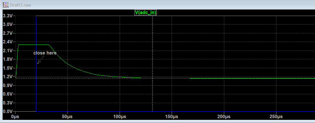
Solution: Case solved!!! Simulations showed that it takes over 100µs for the MOSFET to stabilize and the ADC value to become stable, as shown in the image. However, the code only waits for tens ofµs, so the code needs adjustment.
Increasing the delay time in the interrupt directly won't work, as it will affect the main function's refresh of the digital tube.
A feasible solution is to first shut down the MOSFET in the first interrupt after the heating time, record this in a variable, return to the main function, and then check the variable in the second interrupt to see if the MOSFET was shut down and 500µs (interrupt time) has elapsed before measuring and calculating the temperature.
Important note:
Do not connect the soldering iron during the first run. Without the soldering iron, a temperature of 500+ degrees Celsius is normal for the digital tube. Power off, connect the soldering iron, and confirm the resistance is around 8 ohms. After startup, be careful with the soldering iron and be prepared to unplug the power at any time.
1. The program download interface only has RX, TX, and GND; power is required for downloading, or connect a wire to the VCC of the STC15W408AS or add an additional VCC.
2. The external crystal oscillator is optional. If not connected, select 11.0952MHz for the internal IRC during download.
3. Zero-point drift of LM358 (there is a DT in the code to correct it) (PS: it would be better to replace it with a precision op-amp)
4. DS18B20 code not implemented
5. Vibration switch code in T12 handle not implemented
6. The pin order of the digital tube and TM1650 connection has been adjusted for wiring convenience
7. The buzzer only sounds once when the power is on, I'm too lazy to write the code... as long as it works.
8. When making the PCB, remember to specify the customer's code location. Place the JLCJLCJLCJLC in the digital tube area.
Press
once to change the set temperature to 315 degrees
. Press and hold once and release to change the set temperature to 10 degrees.
You need to
confirm whether the purchased parts match the PCB, including the size. (To be honest, I don't remember the original parts I used. I confirmed it by searching the order records on Taobao.)
1. DC-005 socket
2. KF126 3P (used to connect external power input, with the same function as the DC socket in the first item)
3. KF126 2P (used to connect the switch)
4. KCD11 switch two-pin (the opening on the PCB is 9mm*14mm), you can replace it with other switches yourself
5. DC-DC module, pay attention to the pin order and input (24V+) and output (5V) voltages
6. IRF4905 PMOS TO-220 package
7. GX12-5 aviation connector
8. LM358
9. 9042 passive buzzer (4mm lead pitch) in DIP8 package ; confirm the size yourself.
10. EC11 rotary encoder; buy a cap for a small fee.
11. STC15W408AS SKDIP28 package; note it's SKDIP, narrower than a regular DIP.
12. TM1650 DIP16. 13.
0.28-inch 4-digit common cathode LED display.
14. TL431 TO92.
15. S8050 TO92.
16. DS18B20 TO92 (I didn't write a program to drive this; you don't need to buy it).
17. Resistors, capacitors, and diodes; buy them according to the schematic (104 and 103 capacitors are CBB capacitors, lead pitch should be 5mm; 10uf electrolytic capacitors have a 2mm lead pitch and a diameter of approximately 5.0-5.5mm).
18. M3 screws, 20mm M3 copper pillars (depending on the switch height, see the picture below), 6mm building blocks (I bought 1000 blocks for 12.8 yuan, not enough, there's a hole missing on the bottom, prioritize building the sides, fill in the extra blocks at the bottom), a sheet of transparent plastic film (to block dust, just found one).

(The KF126 2P should theoretically be placed at the bottom to connect to the switch, but it looks better on top).
19. 24V 3A power supply.
20. T12 handle kit
code.
I modified the code to use SDCC. The code is messy and not organized (I just looked at it again. The program logic has clearly been changed, but there are still comments from the original code).
The code package comes with an SDCC compiler. Click build.bat to compile
the generated firmware in the bin directory. If

using the internal IRC, select 11.0952MHz frequency.
Modification suggestion:
the board is a bit exaggerated, reduce it yourself.
The original code measures the temperature every certain period of time and then uses the PID to calculate a new heating time, which is not very good. It's suggested to set the temperature measurement to: turn off the output at 50ms, measure the temperature at 51ms, calculate the PID, and output a new PWM value.
Also...
this was done a long time ago, and I don't remember it very clearly. I used it as practice when I was just starting out (so I made a large 10cm x 10cm board with all through-hole components, haha. If you understand it, you can modify it to be smaller).
Firmware download instructions can be found on Baidu.
(Maybe in two years I'll make a smaller board and reorganize the code.)
If you can't see the schematic and PCB, you can open them by clicking clone. This is a bug in LCSC's code, and they haven't fixed it for so many years.

 The power supply section
  contains some miscellaneous components; these are mainly for connecting to the 32-bit chip.
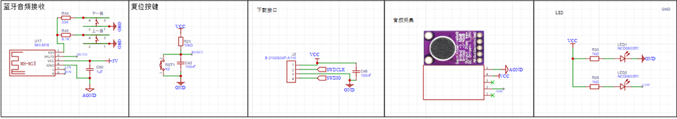
 Next is the 32RCT6. The reason for choosing this chip is its fewer pins for easier soldering, and because a DAC function is required. The RCT6 chip was selected based on the table below.
 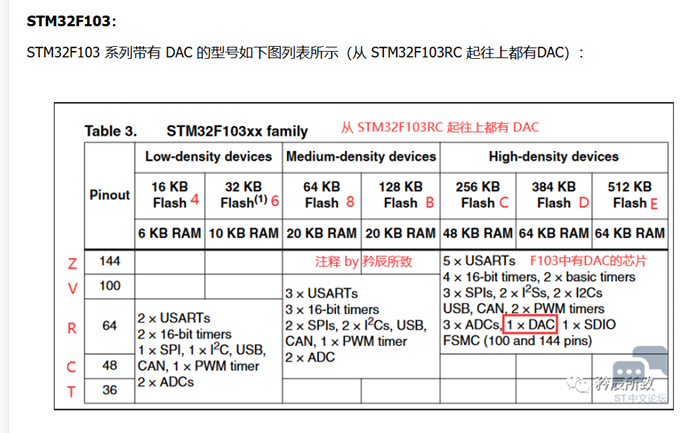 Remember the components you learned before? Connect them to the pins (the pin positions are your choice; details will be explained in the CubeMX configuration
  section later). I won't go into detail about the software; interested readers can download the attached "Introduction" and code package and refer to them.
  Precautions


 京公网安备 11010802033920号

 CY39100V208-125BBI


