Preface:
I stumbled upon this activity by chance, and realizing I only knew how to use the ADC on a development board to read voltage, I decided to join this bootcamp to learn hardware design.
I. Schematic
Design I followed the official hardware tutorials step-by-step to learn schematic design, including calibration reference circuit design and sampling circuit design. Here, I'll summarize some pitfalls I encountered while drawing the schematic, serving as a summary of this project.
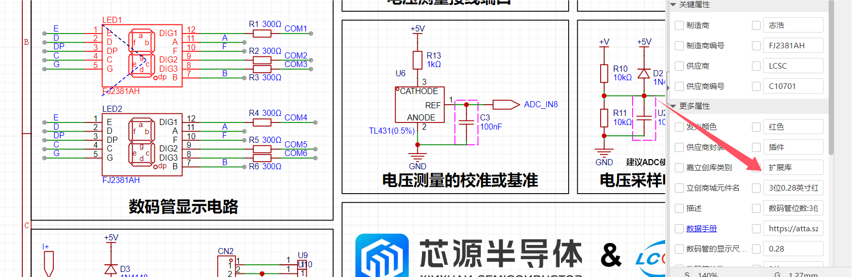
1. Selection of Digital Tubes:
We used 0.28-inch common cathode tubes, but the raw materials were out of stock when purchasing components. Trying to find a substitute, we ended up with 0.38-inch common anode tubes. Therefore, before drawing the schematic, pay attention to component inventory. Choosing appropriate components and having sufficient stock can save you a lot of trouble, as LCSC's online store allows direct import of BOM lists for purchasing. If a replacement is needed, it's easy to make mistakes or forget.
2. Diode Direction:
Diodes are typically used to control the unidirectional flow of current. If connected in reverse, it will cause the component to burn out or become non-conductive.
II. PCB Design
The steps of PCB design mainly include two categories: layout and routing.
1. Layout:
The prerequisite for layout is drawing the board outline. We need to estimate the area occupied by all components, and then draw a slightly larger board outline, with the size as round as possible for easy coordinate adjustment. Then, align one vertex of the board outline with the origin, create rounded corners, and lock it to start placing the components.

2. Component Placement: Prioritize placing the positioning holes (screw holes) at the four corners. At this point, you can use coordinates for precise placement. After placement, lock it again. Next are the terminal components, such as power interfaces, detection interfaces, and download interfaces. These ports that need to interact with the outside world should be placed on the edge of the board or unobstructed. After roughly positioning them, we can start placing other large components. The digital tube can be placed in the center, followed by the core board's header pins. These can be placed together with the digital tube because they involve the most pins, minimizing the number of flying wire crossings. Also, pay attention to the spacing between the two header pins. Finally, place the other resistors, capacitors, etc.
3. Layout Considerations: In addition to the basic placement mentioned above, pay attention to the following: For power supply filter capacitors, place the larger capacitors first, then the smaller ones, to facilitate routing. Also, follow a consistent principle; keep components in the same area aligned and spaced evenly.
Routing:
PCB routing is also crucial; a good layout makes routing much easier. Having reduced flying wire crossings in the previous layout, we'll open the netsheet panel and disable the power and GND flying wires. We'll start by drawing the signal lines.
1. Connect the non-crossing flying wires with conductors. After correct connection, the flying wires will automatically disappear. After routing these, we can use vias to help route the remaining crossing lines.
2. Next are the power lines, which should be appropriately thickened to ensure sufficient current carrying capacity.

3. In the voltage and current detection section, we sometimes need to detect high voltages and currents, so we use copper pours for connection. However, note that the copper pour should be a full connection, not the default scattered one.

4. Finally, enable the GND flying wires and connect all GND connections.
Don't forget DRC!!!
Don't forget DRC! !!
Don't forget DRC!!!

III. Shell Design
When designing the shell, we create it based on the PCB file we've already made. First, draw the 3D outline, setting the wall thickness and top and bottom shell thicknesses, generally greater than 3mm for easy printing.
Roughly draw a box, ensuring its height is greater than the tallest component on the PCB before proceeding with the cutouts: these are mainly for buttons, digital displays, detection points, adjusting resistors, and power terminals. We place the cutout areas on the top layer of the 3D shell, opposite the component locations. The power terminals are on the side, so we also need to make holes on the side.
Finally, for fixation, we can place screw posts at the four screw holes, and then use screws to fix the board to the shell.

IV. Panel Design
We cut down one millimeter from the top layer of the 3D shell to place our panel. The panel material is transparent acrylic. We can add some prompts on it for convenience in using voltage and current; we can also place our favorite pictures, color is supported.

V. Ordering
PCB, 3D shell, components, and panel can all be ordered with one click in the design interface, awesome!
Waiting............
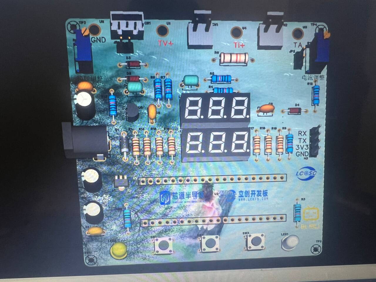
Finally, all the materials arrived, and we started soldering.
VI. Soldering
There are quite a few things to pay attention to during the soldering process, the first being safety.
Then, we need to solder the shorter components first; this is very important, otherwise the taller components will block your soldering torch.
After soldering, we should briefly use a multimeter to check for short circuits in the power supply before powering it on.
VII. Code
Let's follow the official instructions and write the code. The process of following along is not detailed here.
It mainly implements code for voltage and current sampling, mode settings, information storage, and digital tube display.
VIII. Testing
I did this section along with the code, but here I only show the successful test interface.
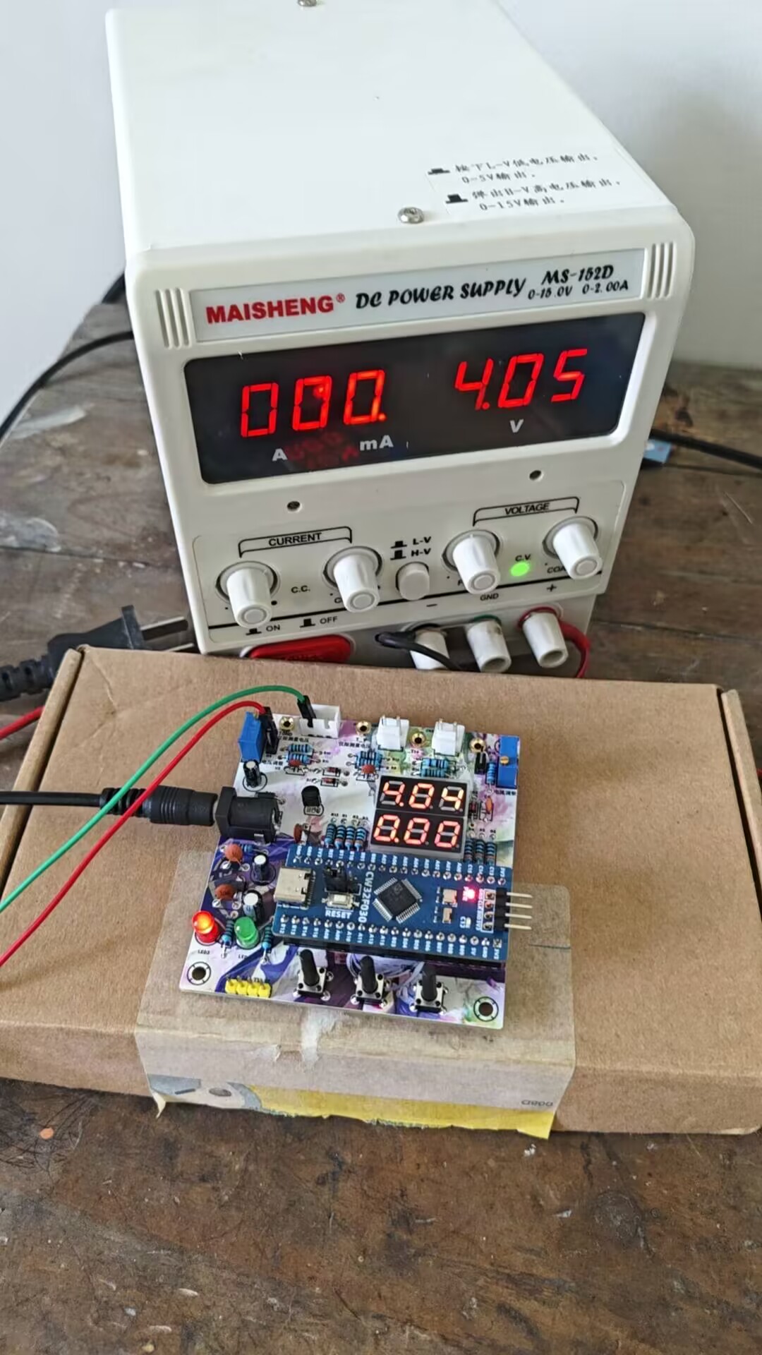
Voltage Test:
When the power supply output is 5V, we calibrated by adjusting to the 5V setting using the button. After adjusting the voltage again, we found that the error could not be eliminated, indicating a hardware problem.
Current Test:
For easier testing, I calibrated a 50mA current to a 500mA current, thus amplifying the current tenfold for easier observation. The results still showed some slight error.

9. Assembly:
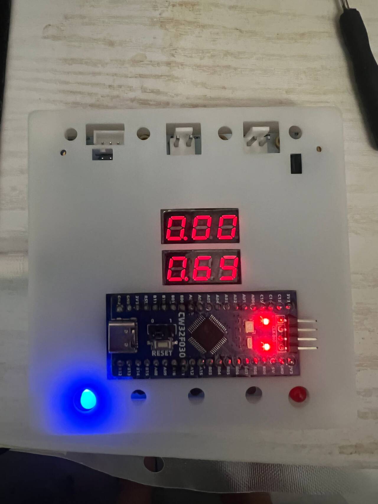
Finally, place the board with the programmed code into the 3D shell, attach our panel, and the voltage and current meter is complete.

Voltage test.jpg
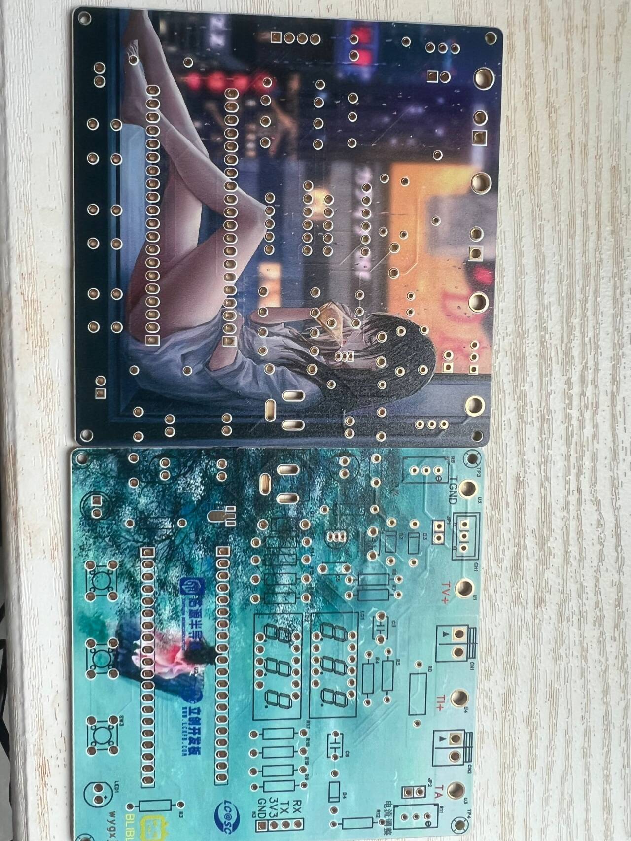
Case + PCB.jpg
Front view.jpg
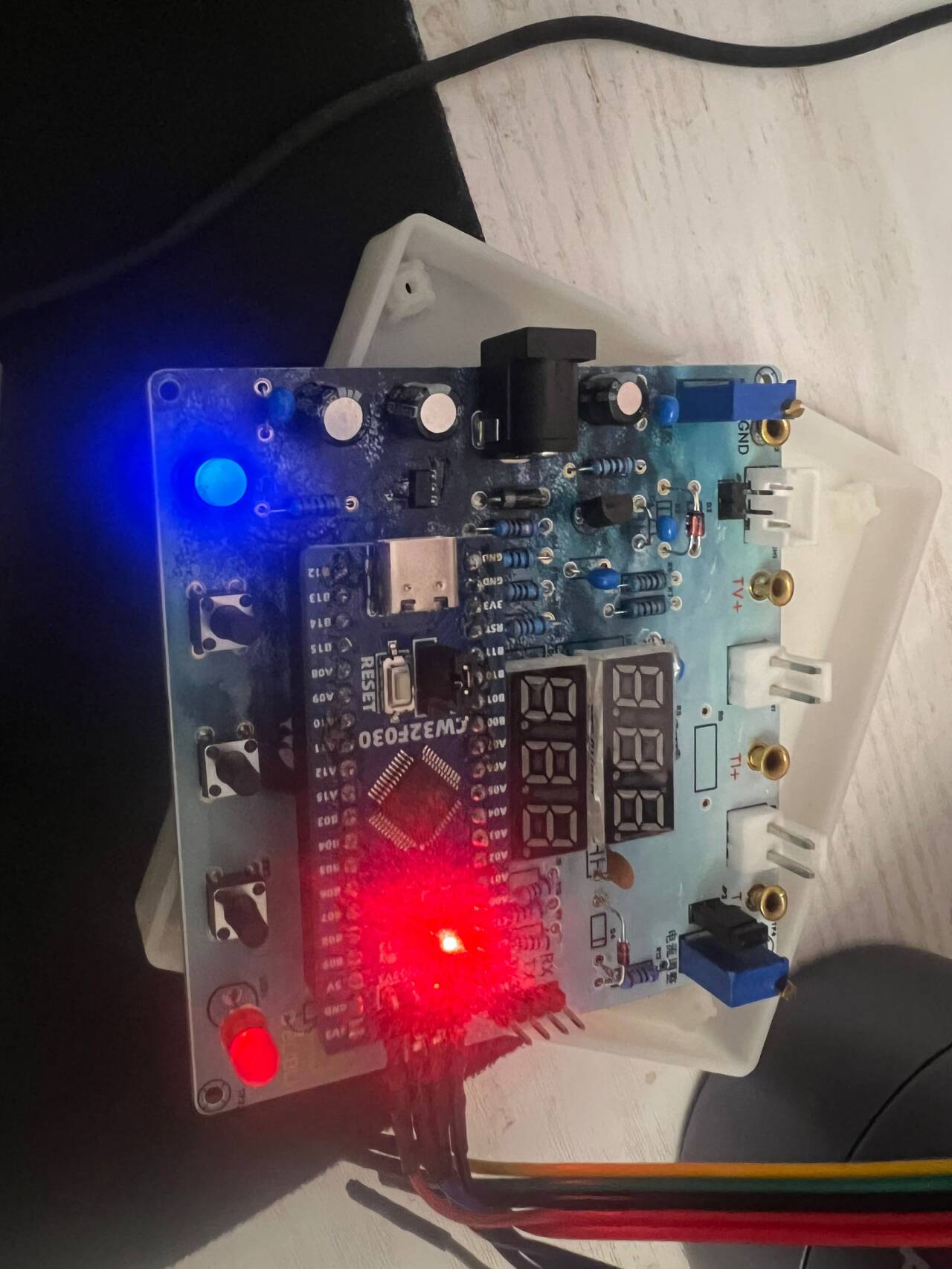
reverse side.jpg
Voltage and Ammeter.zip
PDF_CW32-based voltage and current meter.zip
Altium_CW32-based voltage and current meter.zip
PADS_CW32-based voltage and current meter.zip
BOM_CW32-based voltage and current meter.xlsx
93009
Voltmeter and Ammeter Training Camp
This is a simple voltage and current meter based on the CW32 geostellar development board.
1. Project Function Introduction:
This project is a lightweight, aesthetically pleasing, and accurate voltage and current meter. It uses the CW32 Diwenxing development board and an OLED display to show the measurement data. The project originates from the LCSC Training Camp.
2. Project Attributes:
This is the first time this project has been publicly disclosed.
The project design references the LCSC Training Camp
project. It has not won any awards in other competitions.
It has not participated in any school defenses.
3. Open Source License:
GPL 3.0
4. Hardware Part
: The schematic diagram is provided at the end of the document. For detailed explanations, please refer to the LCSC Training Camp: CW32 Digital Voltage and Current Meter Training Camp Project Tutorial Document | LCSC Development Board Technical Document Center (lckfb.com). A slight difference is the use of an OLED instead of a digital tube. This document mainly discusses some soldering experiences for beginners.
As I am a complete beginner, I purchased the following soldering equipment based on recommendations from experienced users:
an unknown T12 soldering station + Yamazaki solder wire (63 rosin core): Overall, it is very beginner-friendly. The soldering station heats up in 3 seconds, and the leaded solder wire makes it easier for beginners to get started. The rosin core is even more convenient, saving a lot of trouble.
Deer Fairy Teppanyaki + Solder Paste (Needle Tip): If you have the budget, I still recommend using a heating plate. Although this teppanyaki is cheap, it lacks temperature control and requires you to connect the power cord yourself, which poses certain safety hazards.
Since most of the components in this project are surface-mount, and the components are small and densely packed, it is not very user-friendly for beginners. Therefore, this set of equipment provides great assistance. The soldering diagram is as follows:

5. Software
Compilation Environment: Keil5
Burning Method: ST-Link
software is mainly composed of two parts: OLED display and voltage and current data reading.
The program idea of OLED display is that the main control chip CW32 controls the OLED display through the I2C protocol:
I2C is a two-wire bidirectional synchronous serial bus protocol. Bidirectional means that both parties can send and receive data; synchronous means that both parties have the same clock pulse (SCL line).
The complete I2C communication process mainly includes the following steps: master start timing; master address transmission timing; master waiting for slave response timing; master sending read/write data timing; master waiting for slave response timing; stop timing;
voltage and current testing is mainly implemented using the internal ADC of the CW32 main control chip. An analog-to-digital converter (A/D converter), or simply ADC, is an electronic component that converts analog signals into digital signals. A typical A/D converter converts an input voltage signal into an output digital signal. Since digital signals themselves do not have practical meaning, only representing a relative magnitude, any A/D converter needs a reference analog quantity as a conversion standard. A common reference standard is the maximum convertible signal size. The output digital quantity represents the magnitude of the input signal relative to the reference signal. For
the specific tutorial, I referred to the CW32 Digital Voltage and Current Meter Training Camp project tutorial document | LCSC Development Board Technical Document Center (lckfb.com). My software capabilities are limited.
6. The project demonstration video
uses two different dry batteries for testing.
QQ Video 20240819210351.mp4
QQ Video 20240819210356.mp4
79a87a7590af33f8c22d0b571e94588e.mp4
PDF_Voltmeter and Ammeter Training Camp.zip
Altium_Voltage and Ammeter Training Camp.zip
PADS_Voltmeter & Ammeter Training Camp.zip
BOM_Voltage and Ammeter Training Camp.xlsx
93010
Voltmeter and Ammeter
Voltage and current meters based on the CW32 geostellar development board
The voltage and current meter built using the LCSC CW32 Diwenxing development board.
CPU selection:
Key advantages of CW32 in this project
: Wide operating temperature range: -40~105℃;
Wide operating voltage: 1.65V~5.5V (STM32 only supports 3.3V systems);
Strong anti-interference: HBM ESD 8KV; All ESD reliability reaches the highest level of international standards (STM32 ESD 2KV).
Key characteristics of CW32's ADC: This project requires a focus on 4 reference voltage sources. Content from the "CW32x030 User Manual".

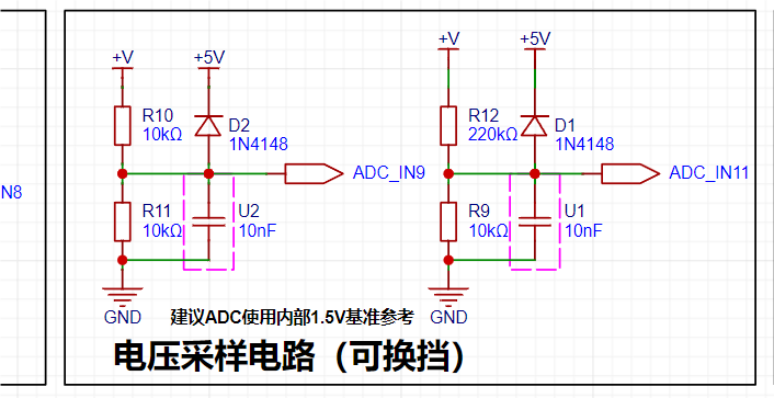
Voltage sampling circuit : The voltage
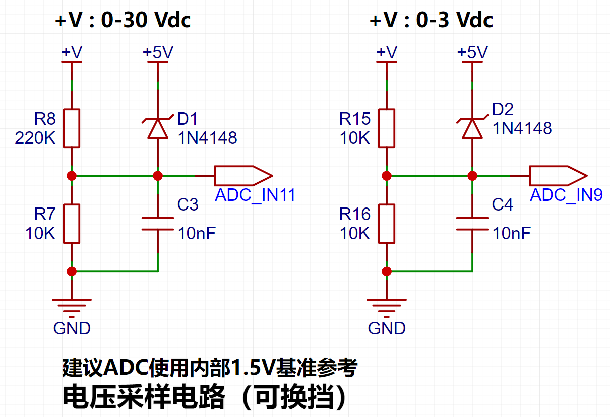
divider resistor in this project is designed to be 220K+10K, therefore the voltage division ratio is 22:1 (ADC_IN11).
Voltage divider resistor selection
design: The maximum value of the measured voltage, for safety reasons, is 30V in this project (the actual maximum can be displayed as 99.9V or 100V).
The ADC reference voltage is 1.5V in this project, and this reference voltage can be configured through the program.
To reduce the power consumption of the sampling circuit, the low-side resistor (R7) is usually chosen as 10K based on experience.
Then, the high-side resistance of the voltage divider resistor can be calculated using the above parameters.
The required voltage division ratio is calculated, i.e., the ADC reference voltage. The input voltage is designed; using known parameters, 1.5V/30V = 0.05 can be calculated.
The high-side resistance is calculated as the low-side resistance/voltage division ratio; using known parameters, 10K/0.05 = 200K can be calculated.
A standard resistor is selected: a resistor slightly higher than the calculated value of 200K is chosen. We usually choose E24 series resistors; therefore, in this project, 220K, which is greater than 200K and closest to the calculated value, is selected.
If, in actual use, the voltage to be measured is lower than 2/3 of the module's design voltage (66V), the voltage divider resistor can be replaced and the program modified to improve measurement accuracy. The following example illustrates this:
Assuming the measured voltage is no higher than 24V and other parameters remain unchanged,
calculations show 1.5V/24V = 0.0625, 10K/0.0625 = 160K. 160K is a standard E24 resistor and can be directly selected, or a higher value 180K can be chosen with some redundancy.
If, in actual use, the voltage to be measured is higher than the module's 99V design voltage, a different resistor can be selected. To achieve a wider voltage measurement range, one can choose to replace the voltage divider resistor or modify the reference voltage. The following example illustrates this:
Assuming the measured voltage is 160V, the solution is to increase the voltage reference to expand the range.
Given that the voltage division ratio of the selected resistor is 0.0145, we can calculate 160V * 0.0145 = 2.32V using the formula. Therefore, we can choose a 2.5V voltage reference to expand the range (increasing the range will reduce accuracy).
Considering the potential fluctuations in the measured power supply, a 10nF filter capacitor is connected in parallel with the low-side voltage divider resistor to improve measurement stability.
Range switching:
In this project, an additional voltage sampling circuit was added. Therefore, we can discuss the significance of range switching for improving measurement accuracy. Multimeters often have multiple range settings for more accurate measurements. By adjusting different ranges, the optimal measurement accuracy of the measured point within the corresponding range can be obtained.
This project requires a combination of hardware and software to achieve this function. When we first use the ADC_IN11 channel mentioned earlier to measure voltages below 30V... If the measured voltage is within 0~3V, use the ADC_IN9 channel for measurement. At this time, due to the reduced voltage division ratio, the measurement accuracy is greatly improved. There are many ways to implement gear shifting, and the development board design provides more design possibilities.
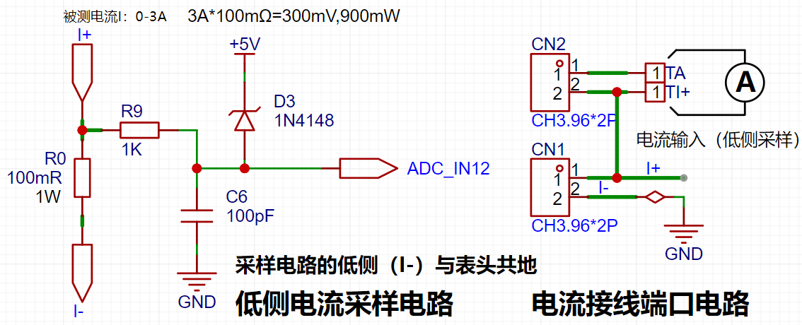
4. Current Sampling Circuit
This project uses a low-side current sampling circuit for current detection. When the low-side of the sampling circuit shares a common ground with the development board's meter interface, please do not solder R0!!!

Design Analysis
The sampling current designed in this project is 3A, and the selected sampling resistor (R0) is 100mΩ. The sampling selection mainly needs to consider the following aspects:
the maximum value of the pre-designed measurement current, which in this project is
the voltage difference brought by the 3A current sensing resistor. It is generally not recommended to exceed 0.5V.
The power consumption of the current sensing resistor should be selected according to this parameter. Considering the power consumption (temperature) problem under high current, a 1W packaged metal wire-wound resistor was selected in this project.
The voltage amplification factor on the current sensing resistor: No operational amplifier was used to build the amplification circuit in this project, so the factor is 1.
Then, the current sensing resistance value can be calculated using the above parameters. Selection:
Since this project... Since no amplifier circuit is used, a larger sampling resistor is needed to obtain a higher measured voltage for measurement.
Considering that a larger resistor would result in a larger voltage drop and higher power consumption, an unlimited selection of a larger resistor is not feasible.
This project uses a 1W package resistor, corresponding to a power consumption of 1W.
Based on the above data, a 100mΩ current sensing resistor was selected. According to the formula, 3A * 100mΩ = 300mV, 900mW can be calculated.
To cope with different operating environments, especially high-current scenarios, the R0 resistor can be replaced with constantan wire or a shunt. The replacement can be selected according to the actual application scenario. For safety and educational purposes, this project will not discuss measurements exceeding 3A in detail, but the principle is the same.
5. Digital Tube Display
This project uses a digital tube as the display unit.
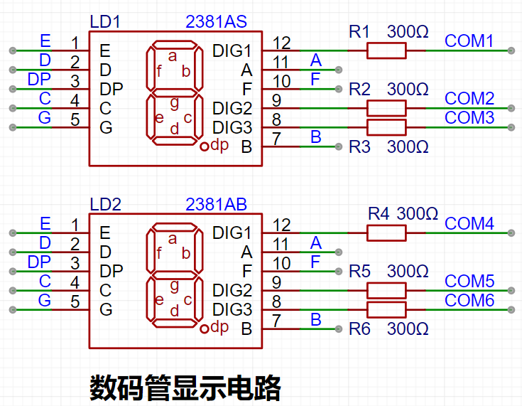
This project uses two 0.28-inch three-digit common-cathode LED displays as the display device. Compared to a display screen, LED displays offer better visibility in complex environments. The brightness of the LED displays can be increased by using smaller current-limiting resistors, depending on the specific needs of the application environment. Furthermore, LED displays have better mechanical properties and are not as easily damaged by external forces as display screens. They are widely used in industrial applications where stability and reliability are crucial. From a development board learning perspective, this makes it easier to learn electronic measurement principles and related development in a targeted manner.
In this project, actual testing showed that the current-limiting resistors (R1~R6) for the LED displays were configured to 300Ω. The corresponding brightness for both red and blue LED displays was good and the brightness was soft and not glaring.
Strictly speaking, the current-limiting resistors should be added to the segments; adding them to the digits would affect the display effect. Our actual design places them in the digits to save a few resistors, but the impact on the display is not significant. Therefore, we add them to the digits for convenience.
The
driving principle of LED displays mainly involves controlling the switching state of each segment of the LED display to display numbers, letters, or symbols. The following is a detailed explanation of the driving principle:
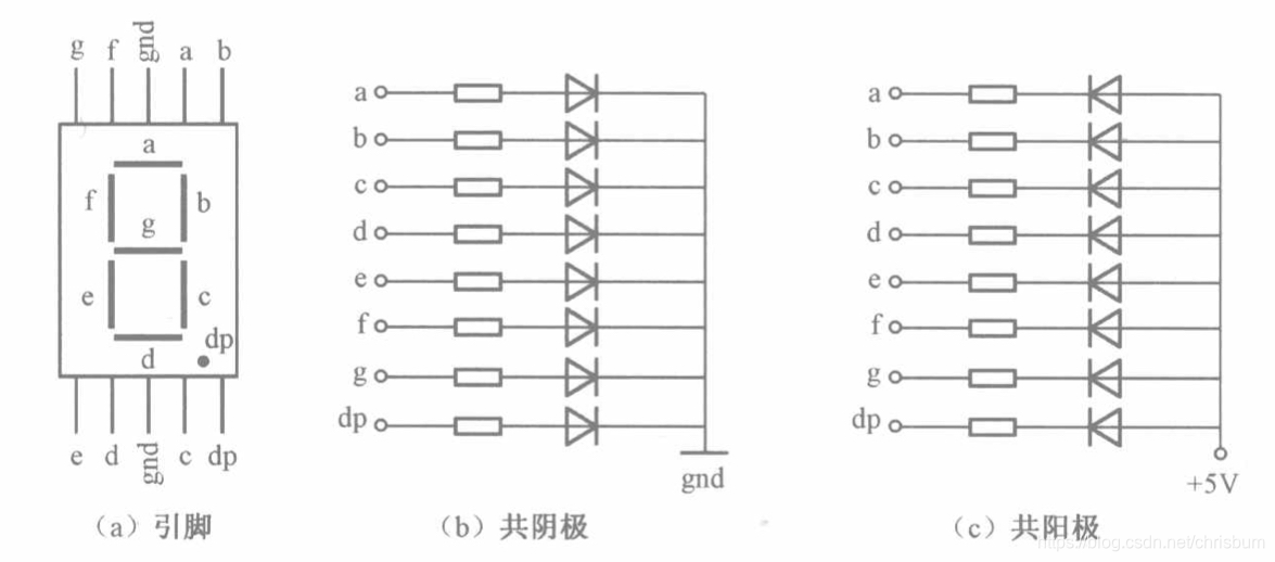
Basic structure of a digital tube:
A digital tube typically consists of seven or eight LED segments (eight segments in this project). Each segment represents a part of the digital tube and can display numbers 0-9, letters AF, etc.
Digital tubes come in two types: common cathode and common anode. The difference lies in whether the common terminal COM (the end connecting all LEDs) is connected to the negative or positive terminal of the power supply.
Driving method:
Segment Selection: Displaying the desired numbers or characters is achieved by controlling the on/off state of each segment of the digital tube. Each segment corresponds to a control signal; when the control signal is on, the segment lights up, and vice versa. (a, b, c, d, e, f, g, dp)
Bit Selection: Selecting the digital tube to be displayed is achieved by controlling its bit lines. Bit line control sets the bit line of the desired digital tube to a high level and the bit lines of other digital tubes to a low level. By continuously switching the state of the bit lines, display switching between multiple digital tubes can be achieved.
Driver Circuit:
The digital tube driver circuit can be implemented using hardware circuits, such as integrated circuits like digital signal processors (DSPs), microcontrollers (MCUs), or shift registers to generate control signals suitable for the LEDs.
These control signals can be in the form of pulse width modulation (PWM) signals, serial data signals, etc. By controlling the frequency, width, and amplitude of these signals, the brightness of the digital tube can be controlled, thereby displaying the desired numbers or letters.
Software Control:
In addition to hardware driver circuits, the digital tube can also be driven by software. By programming and generating control signals suitable for the digital tube, more flexible and complex display effects can be achieved, such as scrolling or alternating display of numbers.
Driving common cathode and common anode digital tubes:
For common cathode digital tubes, the common cathode pin is connected to the negative terminal of the power supply, and the control pin is connected to the output pin of the control chip. When a number needs to be displayed, the control chip outputs the corresponding encoded signal to the control pin, causing the corresponding LED segment to light up.
For common anode digital tubes, the working principle is similar to that of common cathode digital tubes, except that the common anode pin is connected to the positive terminal of the power supply, and the control pin is connected to the output pin of the control chip.
Encoded display:
In order for the digital tube to display the corresponding number or character, the segment data port must output the corresponding character code. For example, to display the number "0", the character code for a common anode digital tube is 11000000B (i.e., C0H), while the character code for a common cathode digital tube is 00111111B (i.e., 3FH). The specific code depends on the actual digital tube.
Dynamic and static display:
Digital tubes can use either static or dynamic display methods. In static display, each of the eight segments of a digital tube is connected to an 8-bit I/O port address. As long as the I/O port outputs a segment code, the corresponding character is displayed and remains unchanged. Dynamic display, on the other hand, lights up each segment of the digital tube one by one in turn, achieving simultaneous visual display through rapid switching.
In summary, the driving principle of a digital tube is to control the switching state of each segment to display numbers, letters, or symbols, and to achieve display switching between multiple digital tubes through segment selection and digit selection. Simultaneously, the driving of the digital tubes can be implemented through hardware circuits or software control, and common cathode or common anode digital tubes can be selected as needed.
This project actually uses dynamic scanning display to drive the digital tubes.
Calculating the required current for the digital tubes
: Since this project uses dynamic scanning display to drive the digital tubes, at any given time, only a maximum of eight segments of the digital tubes (or LEDs) can be lit, or in other words, only one digit can be lit. According to the design, the required driving current is approximately 11mA (IO port high-level voltage 3.3V ÷ 300Ω).
At this point, it is important to ensure that the selected MCU has sufficient current-pull/sinking capability.
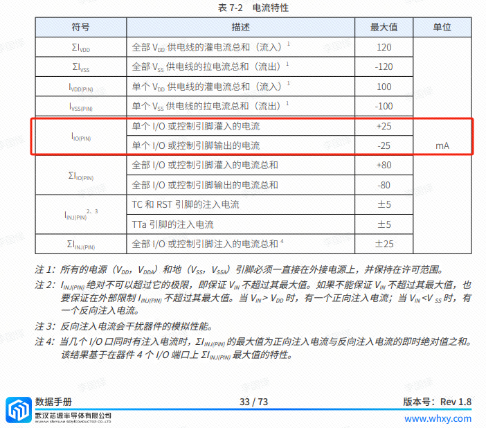
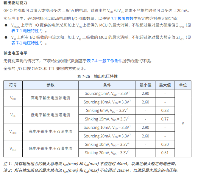
Analysis of the datasheet shows that the CW32 has no issues. (Some chips do not work.)
6. LED Indicators
This project additionally designed a power indicator and an I/O operation indicator.
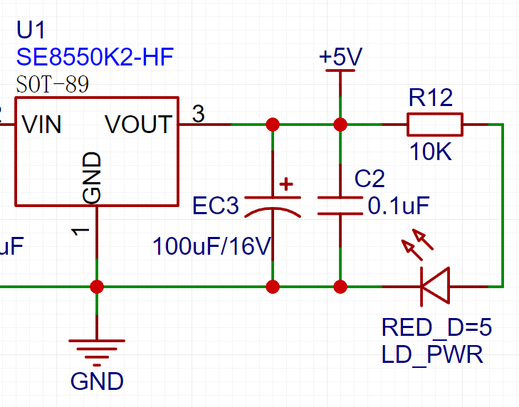
LD_PWR is the power operation indicator

. Since the chip's I/O often has a greater current sinking capability than a current pulling capability, LED1 is designed to be active low (on).
To reduce the current consumption of the LED, some LED brightness is sacrificed, the number of component parameters is reduced, and the current-limiting resistor for the LED is selected as 10K.
7. Button Circuit Design

There are various design methods for the button control circuit. Thanks to the fact that the CW32's I/O port can be configured with pull-up and pull-down resistors internally, the button control circuit on the outside of the chip does not need to be configured. One end of the button is connected to the MCU's I/O, and the other end is grounded. When the button is pressed, the I/O is pulled low.
8. TL431 Circuit Design for Voltage Measurement and Calibration:
This project adds an extra TL431 circuit to provide a 2.5V reference voltage. This can be used to provide an external voltage reference for the chip to calibrate the AD converter. From a product design perspective, due to the inherent ADC performance advantages of the CW32, this circuit is not necessary. This circuit is designed on the development board to learn the relevant application principles.

The TL431 is a relatively "old" device, a classic, and widely used one, still found in many electronic products.
Many beginners may be encountering this device for the first time, so we will briefly explain its principles to help everyone better apply the TL431.
TI defines it as a "Precision Programmable Reference." On the first page of the references, we can focus on several key characteristics.
Precision: Precision indicates that its output voltage is very accurate. I used a ±0.5% accuracy TL431, which measured 2.495V on the board at room temperature. Compared to common Zener diodes, the accuracy is vastly different. In the application circuit diagram, the TL431 is represented by a Zener diode symbol.
Adjustable Output Voltage: The adjustable output voltage is between Vref and 36V. In our project, we use the output Vref voltage, which is approximately 2.5V. Therefore, we use 2.5V in the description, which is approximately equal to Vref.
Sinking Current Capability: This refers to how much current the output voltage pin can provide. This is greatly influenced by the resistance value (R13) in the application circuit. It should not be less than 1mA. If there is no need for sinking current, do not design the current to be too high, as this will cause unnecessary power consumption.
WeChat image_20240817191553.jpg
efe414aef4294642d3c1026541a1aebe.mp4
PDF_Voltage and Current Meters.zip
Altium_voltmeter_currentmeter.zip
PADS_Voltage and Current Meter.zip
BOM_Voltage and Current Meter.xlsx
93011
CW32 Voltage and Current Meter
The voltage and current meters made in the training camp
I. Design Background
An ADC (Analog-to-Digital Converter) is an indispensable key component in electronic systems. It converts continuous analog signals into digital signals, enabling digital processing and analysis. ADCs play a crucial role in signal conversion, measurement and data acquisition, control system input, and communication and signal processing. Their widespread application promotes the intelligent and precise control of electronic equipment across various industries, and is one of the key factors driving modern technological progress. Digital voltmeters and ammeters combine ADC technology with circuit measurement principles, accurately converting analog voltage and current signals into digital displays for easy reading and analysis by electronic engineers. This device not only improves the accuracy and efficiency of circuit measurements but also helps engineers better understand circuit behavior, serving as a powerful assistant in electronic design and troubleshooting, and playing a vital supporting role in the work of electronic engineers. In product applications, digital voltmeters ensure the accuracy and safety of circuit design, while also providing strong support for product quality control and subsequent maintenance. Learning to design and build a digital voltmeter and ammeter
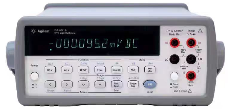
using a benchtop digital multimeter (Agilent 34401A)
is highly beneficial for improving one's professional skills. This digital voltmeter and ammeter project covers multiple aspects, including microcontroller circuit design and implementation, signal acquisition and processing circuit design, user interface development and optimization, and product appearance design. It integrates knowledge from multiple fields such as electronics, microcontroller programming, circuit design, and industrial design. Considering the learning pace and knowledge absorption capacity of beginners, we have specially launched this introductory-level digital voltmeter and ammeter project, which is very suitable for beginners in electronics and those who want to learn more about microcontroller applications. This project has the following highlights:
it adopts a core board plus expansion board design concept and uses plug-in components, making learning simpler and exploration more in-depth;
the core board uses the domestic Wuhan Xinyuan Semiconductor CW32 as the main controller, while also being compatible with other similar development boards; however, the CW32 has advantages.
The project is highly comprehensive and practical, and after completion, it can be used as a desktop instrument;
the project has abundant learning materials, including circuit design tutorials, PCB design, code programming learning, and training for engineers' debugging skills.
II. Hardware Design
1. Voltage Sampling Circuit
The voltage divider resistor in this project is 220K+10K, so the voltage division ratio is 22:1 (ADC_IN11).
The voltage divider resistor is
selected to measure the maximum voltage. For safety reasons, this project uses 30V (the actual maximum can be displayed as 99.9V or 100V).
The ADC reference voltage is 1.5V in this project, and this reference voltage can be configured through the program.
To reduce the power consumption of the sampling circuit, the low-side resistor (R7) is usually chosen as 10K based on experience.
Then, the high-side resistance of the voltage divider resistor can be calculated using the above parameters.
The required voltage division ratio is calculated, i.e., the ADC reference voltage. The input voltage is designed; using known parameters, 1.5V/30V = 0.05 can be calculated.
The high-side resistance is calculated as the low-side resistance/voltage division ratio; using known parameters, 10K/0.05 = 200K can be calculated.
A standard resistor is selected: a resistor slightly higher than the calculated value of 200K is chosen. We usually choose E24 series resistors; therefore, in this project, 220K, which is greater than 200K and closest to the calculated value, is selected.
If, in actual use, the voltage to be measured is lower than 2/3 of the module's design voltage (66V), the voltage divider resistor can be replaced and the program modified to improve measurement accuracy. The following example illustrates this:
Assuming the measured voltage is no higher than 24V and other parameters remain unchanged,
calculations show 1.5V/24V = 0.0625, 10K/0.0625 = 160K. 160K is a standard E24 resistor and can be directly selected, or a higher value 180K can be chosen with some redundancy.
If, in actual use, the voltage to be measured is higher than the module's 99V design voltage, a different resistor can be selected. To achieve a wider voltage measurement range, one can choose to replace the voltage divider resistor or modify the reference voltage. The following example illustrates this:
Assuming the measured voltage is 160V, the solution is to increase the voltage reference to expand the range.
Given that the voltage division ratio of the selected resistor is 0.0145, we can calculate 160V * 0.0145 = 2.32V using the formula. Therefore, we can choose a 2.5V voltage reference to expand the range (increasing the range will reduce accuracy).
Considering the potential fluctuations in the measured power supply, a 10nF filter capacitor is connected in parallel with the low-side voltage divider resistor to improve measurement stability.
Range switching:
In this project, an additional voltage sampling circuit was added. Therefore, we can discuss the significance of range switching for improving measurement accuracy. Multimeters often have multiple range settings for more accurate measurements. By adjusting different ranges, the optimal measurement accuracy of the measured point within the corresponding range can be obtained.
This project requires a combination of hardware and software to achieve this function. When we first use the ADC_IN11 channel mentioned earlier to measure voltages below 30V... If the measured voltage is within 0~3V, then the ADC_IN9 channel is used for measurement. In this case, the measurement accuracy is greatly improved due to the reduced voltage division ratio. There are many ways to implement gear shifting, and the development board design provides more design possibilities.
PDF_CW32 Voltage and Current Meter.zip
Altium_CW32 voltage and current meter.zip
PADS_CW32 Voltage and Current Meter.zip
BOM_CW32 Voltage and Current Meter.xlsx
93012
LCSC GeoStar CW32 Digital Voltage and Current Meter Expansion Board
Voltage and current meter based on CW32F030
The main functions of the voltage and current meter based on CW32F030
are: to measure and display voltages from 0-30Vdc and currents from 0.1-3A.
Key advantages of CW32 in this project include
: wide operating temperature range (-40~105℃)
; wide operating voltage range (1.65V~5.5V, STM32 only supports 3.3V systems)
; superior anti-interference capabilities (HBM ESD 8KV, all ESD reliability reaches the highest international standard level (STM32 ESD 2KV))
; and a better ADC (12-bit high-speed ADC with ±1.0LSB INL 11.3ENOB, multiple Vref reference voltages... (STM32 only supports VDD=Vref);
and stable and reliable eFLASH technology.

The sampling current designed for this project is 3A, and the selected sampling resistor (R0) is 100mΩ. The following aspects need to be considered when selecting the sampling resistor:
the maximum value of the pre-designed measurement current;
the voltage difference caused by the 3A current sensing resistor in
this project; and the power consumption of the current sensing resistor, which should generally not exceed 0.5V. A suitable package should be selected based on this parameter. Considering the power consumption (temperature) issue under high current, a 1W packaged metal-wound resistor was chosen
. The voltage amplification factor of the current sensing resistor: No operational amplifier is used in this project, so the factor is 1. The
current sensing resistance value can then be calculated using the above parameters. Selection:
Since no amplifier circuit is used in this project, a larger sampling resistor is needed to obtain a higher measured voltage for measurement.
Considering that a larger resistor will result in a larger voltage difference and higher power consumption, a larger resistor cannot be selected indiscriminately.
A 1W packaged resistor was selected in this project, with a corresponding temperature rise power of 1W.
PDF_LCSC GeoStar CW32 Digital Voltage and Current Meter Expansion Board.zip
Altium_LCSC·Diwenxing CW32 Digital Voltage and Current Meter Expansion Board.zip
PADS_LCSC·Diwenxing CW32 Digital Voltage and Current Meter Expansion Board.zip
BOM_LCSC·Diwenxing CW32 Digital Voltage and Current Meter Expansion Board.xlsx
93013
Voltmeter and Ammeter
The CW32 digital voltmeter and ammeter training program includes calibration and setting functions.
The CW32 digital voltmeter and ammeter training program includes calibration and setting functions.
Modes can be switched using the left-side buttons. The middle button confirms calibration. The right-side buttons control the measurement mode.
Mode 0: Measurement mode;
Mode 1: 5V voltage calibration setting;
Mode 2: 15V
voltage calibration setting; Mode 3: 0.5A current calibration setting;
Mode 4: 1.5A current calibration setting.
Ideal for beginners!


202408201152.mp4
PDF_Voltage and Current Meters.zip
Altium_voltmeter_currentmeter.zip
PADS_Voltage and Current Meter.zip
BOM_Voltage and Current Meter.xlsx
93014
Voltage and current meters based on LCSC development board (Geographic Star).
This is a voltage and current measuring instrument based on the LCSC development board Diwenxing CW32.
This is a voltage and current measuring meter based on the LCSC CW32 development board. The circuit uses LCSC's color PCB immersion gold process, making the circuit more reliable and aesthetically pleasing. [Images !
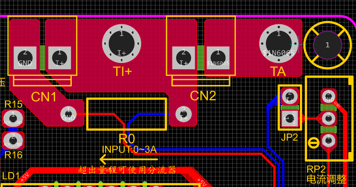
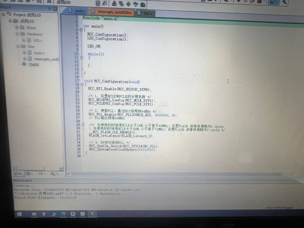
[e1b86cc7e397551504a3610f37036a1c_720.png] [ 62374a529e42e833e6d15ddf923f1af2_720.png] The casing and panel are also 3D printed , making the product complete! ![a79227aacce984c1d922adbf53381fe8_720.png] ![676828e3eac44ae58389dd87c5548b69_720.png] The power supply section adopts a wide voltage input of 5V to 12V, and uses the SE85550k2 low dropout LOD chip to ensure stable operation of the power supply. At the same time, a reverse connection protection diode is connected in series in the circuit to ensure the safety of the power input . ![image.png] The core board uses the LCSC CW32F030C8T6 development board (core board). Its advantages are as follows: Wide operating temperature: -40~105℃ ![image.png] Wide operating voltage: 1.65V~5.5V (STM32 only supports 3.3V system) Strong anti-interference: HBM ESD 8KV All ESD reliability reaches the highest level of international standards (STM32) (ESD2KV) This project focuses on a better ADC: a 12-bit high-speed ADC achieving ±1.0LSB INL 11.3ENOB, multiple Vref reference voltages... ... (STM32 only supports VDD=Vref). Stable and reliable eFLASH technology. (Flash0, etc.) This project uses a voltage divider circuit to achieve high voltage acquisition, designed to acquire voltages up to 100V, currently configured to acquire voltages of 0-30V. The ADC reference voltage in this project is 1.5V, which can be configured through the program. During the design of this project, an additional 1N4148 (D1, etc.) was added to the sampling circuit as a clamping diode to minimize the risk of chip pin damage due to incorrect voltage input during learning and debugging. Diode clamping is an important electronic circuit design technique. Its main function is to protect the circuit by limiting the voltage amplitude, preventing damage or malfunction caused by excessively large or small signals. This project uses a low-side current sampling circuit for current detection. The low-side of the sampling circuit shares a common ground with the development board's meter interface. The sampling current is 3A, and the selected sampling resistor (R0) is 100mΩ. The selection of the sampling resistor mainly needs to consider the following aspects: the maximum value of the pre-designed measurement current; the voltage difference caused by the 3A current sensing resistor in this project; generally, it is not recommended to exceed 0.5V ; the power consumption of the current sensing resistor should be selected based on this parameter; considering the power consumption (temperature) issue under high current, a 1W packaged metal wire-wound resistor was selected in this project; the voltage amplification factor across the current sensing resistor: Since no operational amplifiers were used to build the amplification circuit, the PCB layout for a gain of 1 requires special attention. Although the I- network and GND network are electrically the same, it's important to note that a large current flows through I-, making it a "power ground." Even though this point is grounded, current fluctuations can cause changes in the network level, thus treating it as an "interference source." The GND network is the negative terminal of the meter's power supply, i.e., "signal ground." Furthermore, since the microcontroller's AGND and the meter's GND are not isolated, the meter's GND can be considered a "sensitive ground," requiring protection from interference. In circuit design, avoid connecting all GNDs together indiscriminately. This is also why copper plating was not used in this project design. In the diagram above, the yellow arrows indicate the path of high current flow: current flows in through the I+ pin of the interface, through the sampling resistor, and out through the I- pin of the interface. Some may wonder why two current sampling interfaces, CN1 and CN2, are provided. Current sampling is connected in series to the circuit under test. Two interfaces are provided for debugging (i.e., for learning development board requirements). For normal measurements, only CN1 needs to be connected. When the project requires connecting to devices such as a multimeter for comparison and verification, pin 1 of CN2 (red wire - current in) and pin 2 of CN1 (black wire - current OUT) must be used simultaneously. This project uses a voltage divider circuit to achieve high voltage acquisition, designed to acquire up to 100V; the current configuration acquires voltages from 0-30V. [Image 1] The sampling current designed for this project is 3A, and the selected sampling resistor (R0) is 100mΩ. The following aspects should be considered when selecting the sampling resistor: the maximum value of the pre-designed measurement current; the voltage difference caused by the 3A current sensing resistor in this project; generally, it is not recommended to exceed 0.5V ; the power consumption of the current sensing resistor should be selected based on this parameter; considering the power consumption (temperature) issue under high current, a 1W packaged metal wire-wound resistor was selected; the voltage amplification factor across the current sensing resistor: no operational amplifier is used to build the amplification circuit in this project, therefore the factor is 1. [Image 2] Development environment installation (MDK 5.33 version recommended), DAPLINK downloader, firmware library. The firmware library can be downloaded from the official website: www.whxy.com. Common debuggers such as STLINK, DAPLINK, PWLINK, WCHLINK, JLINK, etc., that support Cortex-M are acceptable. I used PWLINK, where verf is 3.3V. ![e59aa5fdd74ee7ca86d303e0f5bc3e92_720.png] Connect the development board, open Example 1, compile without errors, flash and light up LED1 . ![1c02a3354d6f456dd16023a89adb5990_720.png] ![eef096da0e4ded95ef6a60a671dedd00_720.png] Directly input Experiment 9. [e37f04b60d57849cbbf34265f5f64b93_720.png] Shorting caps on JP1 and JP2 respectively simulates the measurement of internal voltage and current. A multimeter is connected, and the data is basically consistent. Use button 1 to select the function and button 2 for calibration, as follows: Define 5 working modes. Key K1 is used to switch display modes. Key K2 sets the parameter value for the corresponding mode and saves it to FLASH. Key K3 returns to mode 0. Mode 0: Displays normal voltage and current values (the upper row of digital tubes displays the voltage value *.V or .*V automatically switches, the lower row displays the current value _.**A).


Mode 1: 5V Voltage Calibration Setting. The top row of the digital display shows 5.05. The bottom row displays the current voltage value in _V or ._V. In this mode, the multimeter should be set to 5.00V when measuring the measured bit. Pressing the K2 key will calibrate the current value to 5V.
Mode 2: 15V Voltage Calibration Setting. The top row of the digital display shows 5.15. The bottom row displays the current voltage value in _V or ._V. In this mode, the multimeter should be set to 15.0V when measuring the measured bit. Pressing the K2 key will calibrate the current value to 15V.
Mode 3: 0.5A Current Calibration Setting. The top row of the digital display shows A.0.5. The bottom row displays the current current value in _.**A. Pressing the K2 key will calibrate the current value to 0.5A.
Mode 4: 1.5A Current Calibration Setting. The top row of digital tubes displays A.1.5. The bottom row displays the current value *.**A. Pressing the K2 key calibrates the current value as 1.5A. Attached video demonstration:
In actual use, the voltage at I+ simulates the voltage drop across the unsoldered 100mΩ sampling resistor. At this time, the simulated measured current value I<sub>measured</sub> = the voltage value Vi+ ÷ 100mΩ, which is also exactly equal to the measured voltage value multiplied by 10. That is, it provides a simulated current measurement range of 0~2.38A. Set the multimeter or high-precision benchtop digital multimeter to the voltage measurement port, with a range within 3V. Insert the black negative probe into the T_GND interface next to the voltage measurement terminal, and the red positive probe into the TI+ port for current measurement to measure the actual voltage value of I+.
DXF_PCB1_2024-08-03.dxf
lcsc.png
CW32 Electric Panel_Panel_1_2024-08-09.epanm
1280X1280 (1).PNG
1280x1280.PNG
KEIL5 Project Template - CW32F030.zip
a0e166bbf05ea9b1b22265a66e25a689.mp4
98d91f96b444e5180420f48f0f12658d.mp4
PDF_Voltage and Current Meters Based on LCSC Development Board (Diwenxing).zip
Altium-based voltage and current meter using LCSC development board (Diwenxing).zip
PADS_Voltage and Current Meter Based on LCSC Development Board (Diwenxing).zip
BOM_Voltage and Current Meter Based on LCSC Development Board (Diwenxing).xlsx
93015
electronic


 京公网安备 11010802033920号

 M38223E3MXXXHP


