TP78_FOC
Demo Video: https://www.bilibili.com/video/BV1jVpneNEpq/
The TP78_FOC is an expansion module for an FOC-controlled brushless motor rotary keypad.
It supports use as a TP78 slave module, synchronizing lighting effects and sleep/wake functionality with the TP78. It

supports VIA key remapping, Aura Sync in USB mode, volume control, Surface Dial control, Pomodoro timer, and free keyboard/mouse key mapping.

Hardware compatibility includes both magnetic and mechanical switches.

Firmware upgrades support USB online updates.
(Note the open-source license, GPL 3.0. Please respect open source. Welcome to discuss. Discussion group: 678606780)
Material List:
Hardware
Name
Quantity
Knurled Nuts M2 3 3
12
Screws M2 * 7
2
Screws M2 * 5
4 Screws
M2 * 3
8
Screws M2 * 12
5
Cable
Name
Quantity
0.5mm Pitch FPC Cable Reverse 6cm 4p
2
0.5mm Pitch FPC Cable Reverse 10cm 12p
1
1.25mm 10p Reverse Cable
1
Other Welded Components
Name
Quantity
Purchase Link
Magnetic Connector 4p 2.54 Pitch (Male + Female)
1
Strain Gauge BF120-3AA
4
【Taobao】https://m.tb.cn/h.gOxxHMXD9mmKU2Z?tk=Nbgi34SweAL CZ0002 "Reinforced Concrete Strain Gauge BF120-3AA 1K 350R" BX120-20AA 30/50/80/100AA" Click the link to open directly or search on Taobao to open directly.
OK Line
1
Non-welded Parts
Name
Quantity
Purchase Link
1. 28-inch round LCD screen
1.
800mAh lithium battery PH2.0 positive interface
1.
8mm*1mm round feet
4.
Acrylic hand glue
1.
502 glue
1.
Double-sided tape
1.
Carpooling link
: https://item.taobao.com/item.htm?ft=t&id=828180761483
Model open source address
: https://makerworld.com/zh/models/604167
Firmware download
Use Espressif's official ESP32 tool to upgrade (not recommended for beginners), tool name: flash_download_tool_3.9.7.exe (version number can be new or old) and esptool.exe.
Usage steps:
(1) Connect the USB Type-C interface and enter the tool directory on your computer;
(2) Open the command prompt window, enter: .esptool.exe run, and the following prompt will appear;

(3) Double-click to open flash_download_tool_3.9.7.exe;
(4) Configure according to the options in the picture;

(5) After clicking OK, load the bin files of the 4 partitions according to the options in the picture;

(6) Note that you should select the corresponding COM port. After entering the bootloader, a new COM port will be added;
(7) Click START until the download is complete and then restart.
Upgrade firmware using TP78 integrated tool.
TP78 integrated tool is a universal host computer tool for TP78 series keyboards. Compared with method 1, it is simpler to upgrade firmware. Power loss during the upgrade process will not damage the current firmware, making it safer.
Tool download address:
https://github.com/ChnMasterOG/TP78-Integrated-Tools/releases/download/V1.0.0/TP78.Integrated.Tools.zip
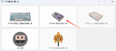
(1) Connect the USB Type-C interface, open the tool on the computer, and select TP78foc firmware upgrade tool;
(2) Click to select firmware and then click update firmware. Note: Here, you only need to select the main partition of the firmware - firmware.bin.

Installation steps
Soldering core board PCB
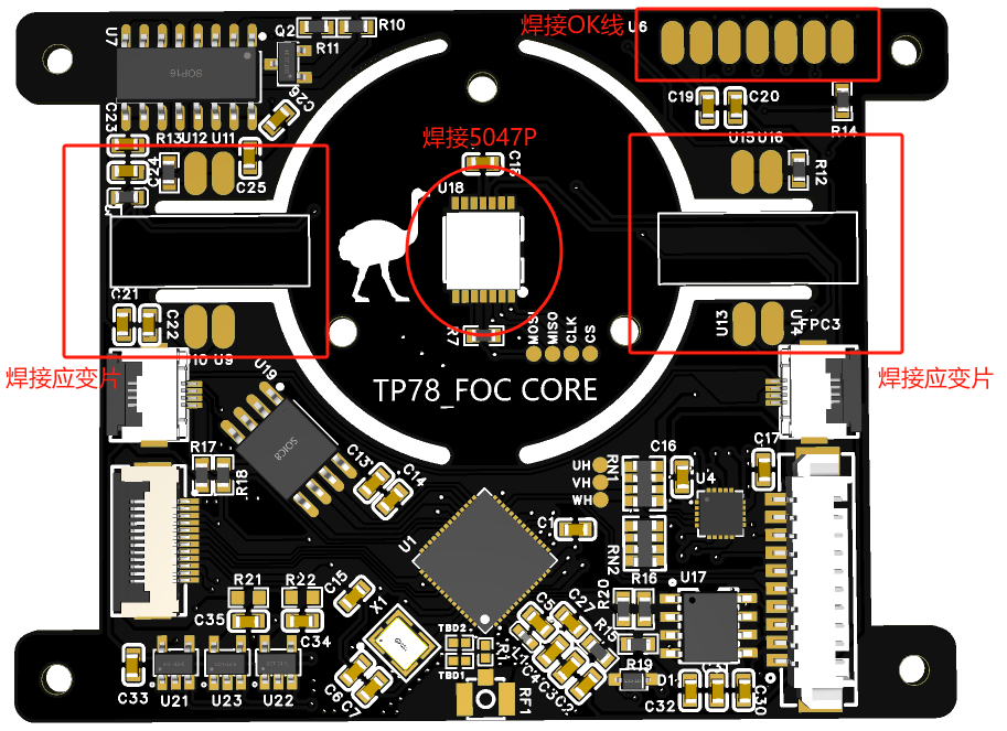
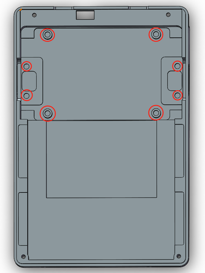
Soldering completed image:
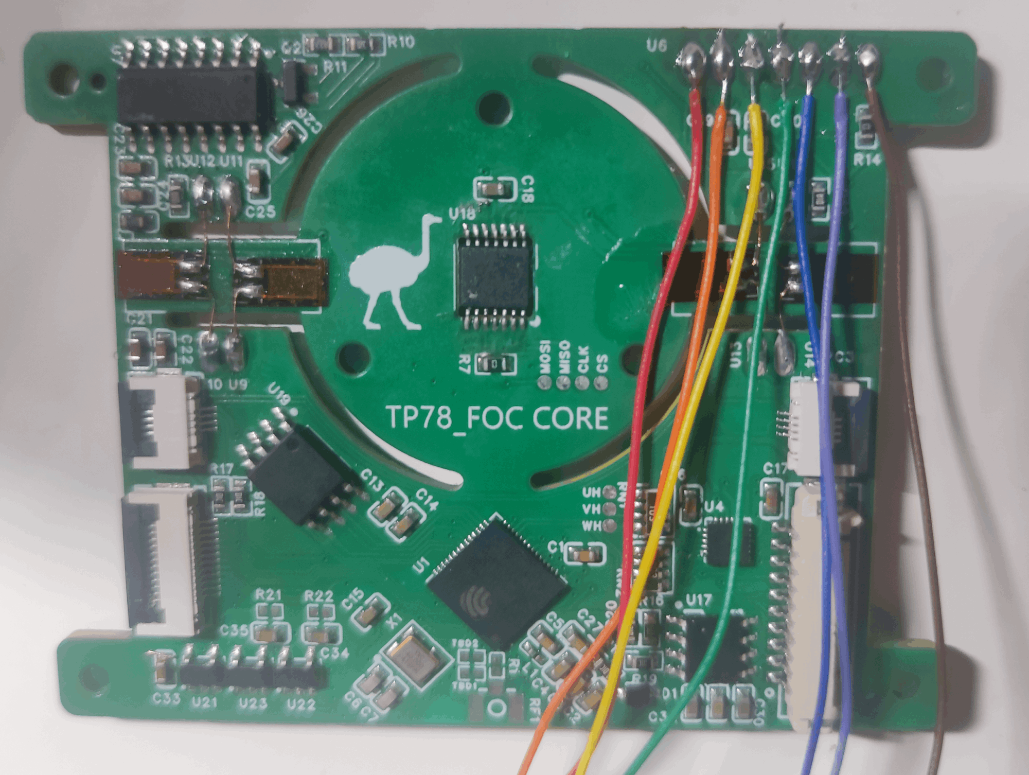
Note: Remember the color order of the OK line, from left to right, they correspond to VCC/BLK/DC/SCL/SDA/RES/GND respectively. The red circle part of
the recessed knurled nut
needs to be hot-pressed into the M2×3×3 knurled nut .

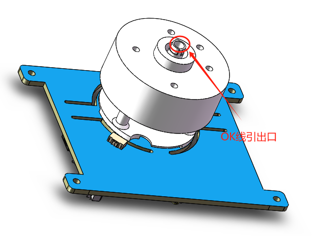
Install the motor
Connect the motor to the core board with the LCD support base printout, pull out 7 OK lines, and insert the motor ribbon cable into the terminal on the top surface of the PCB. Finally, use 3 M2×12 screws to tighten the back.
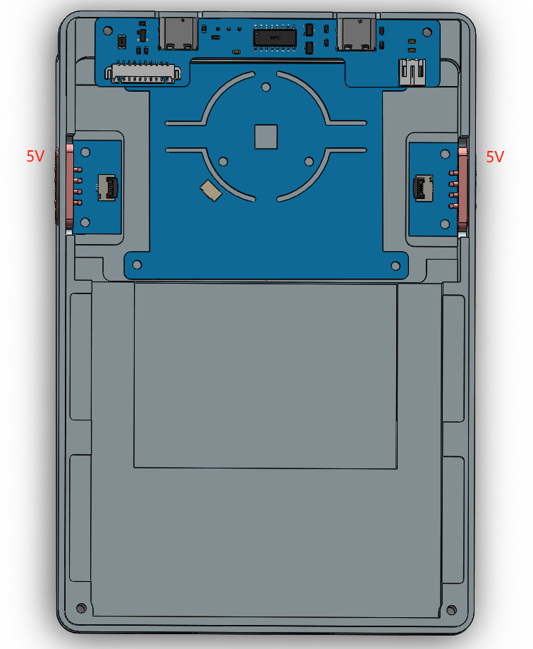
Install the switch plate
Install the switch and keycap, and install the silicone pellets of the positioning plate. First,

install the
left and right magnetic charging boards using four M2×3 screws. Then, connect all the ribbon cables on the core board, using a 4-pin FPC ribbon cable to connect the left and right magnetic charging boards, ensuring 5V is available near the switch. Finally, tighten the four surrounding screws.
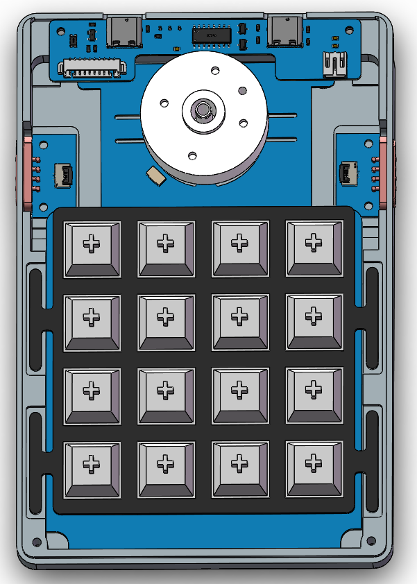
Next, secure the core board with the motor installed using four M2×3 screws.
Connect the power supply board and core board using a 1.25mm reverse 10-pin ribbon cable.
Connect the shaft board and core board using a 12-pin reverse FPC cable.
Attach the battery to the bottom cover with double-sided tape, then connect the battery and power supply board.
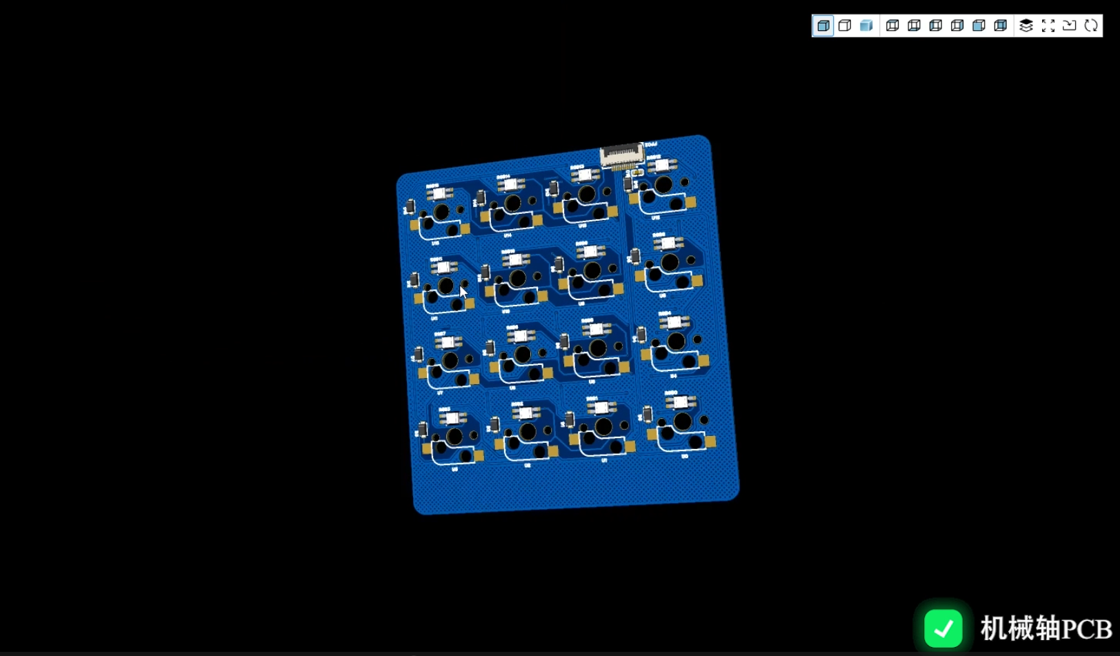
The assembled model is shown in the image below.
Install the top cover
using two M2×7 screws, tightening them to the holes on the power supply board side.
Tighten the remaining two holes with two M2×12 screws.
Secure the 3D printed part and motor to the underside of the knob housing
using four M2×5 screws. Ensure

the upper surface of the LCD support
is firmly secured; if it easily comes loose, use super glue to help it adhere.

Install the LCD panel
by connecting the LCD and LCD adapter board.
Then solder the LCD adapter board and the seven OK wires, following the previously remembered order and corresponding PCB silkscreen markings.
Next, place the LCD adapter board on the upper surface of the LCD support and secure it with a suitable amount of super glue.

Finally, attach the LCD screen and LCD panel using double-sided tape, ensuring the LCD is upright and not crooked. Finally
,
replace the knob cover and use acrylic glue to secure the round acrylic piece to the knob cover.
Finally, install the feet.

Note:
This module is a knob module, not a motor module; therefore, high-speed rotation and forced rotation of the motor in limit mode are not recommended.
Upon initial power-on, motor calibration, button code reset, screen calibration, and pressure calibration must be performed. Please refer to the attached instruction document for details.


 京公网安备 11010802033920号

 JANTX1N4370BURTR-1


