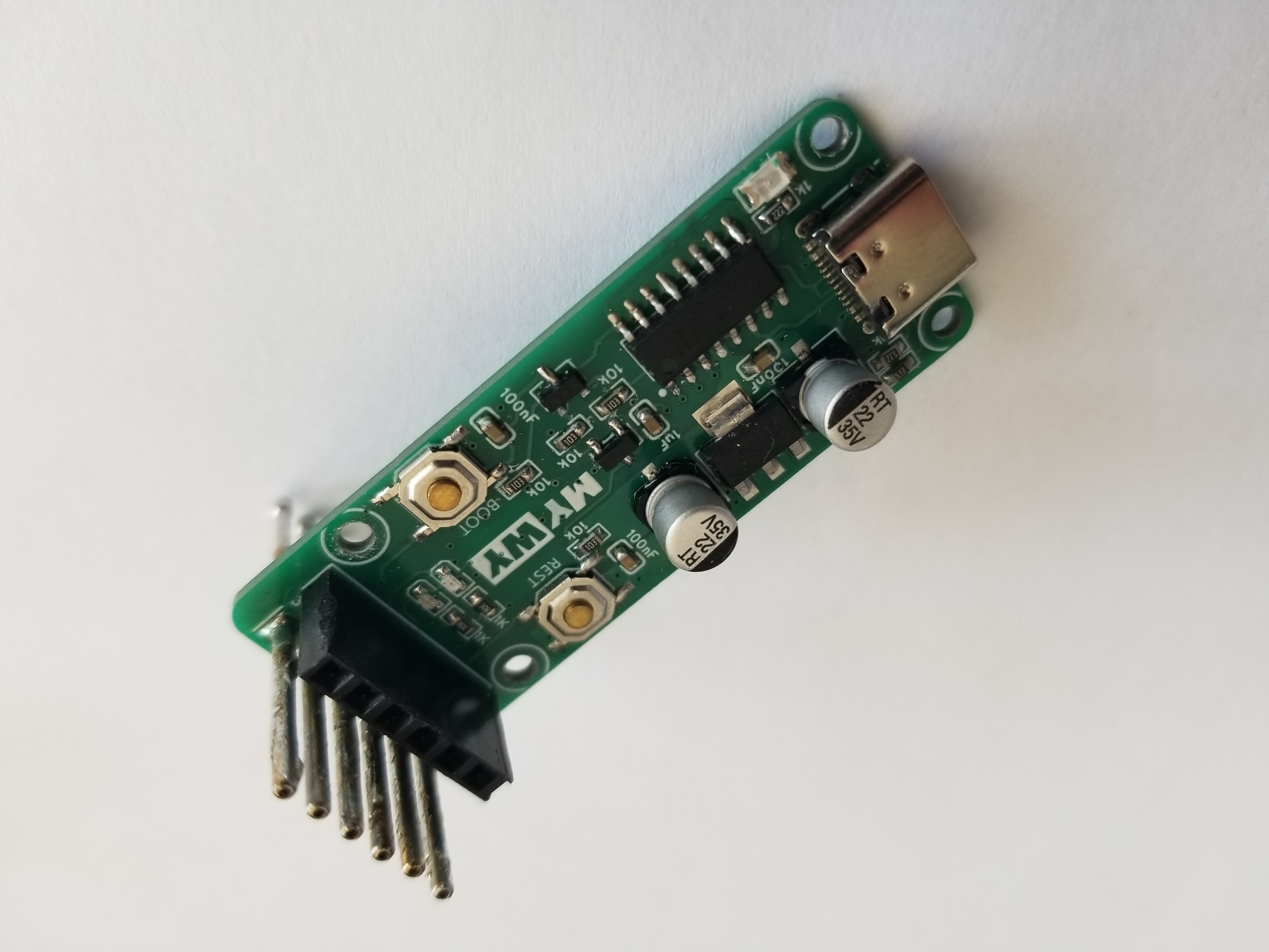
The basic functions of the minimum board have been verified and it can be programmed using hardware USB. It includes a 5V reference voltage chip for the ADC, an external EEROM, an additional 3.3V power supply, and multiple buttons and LEDs. All pins, as well as VCC and GND, are exposed, requiring few components while offering rich functionality.
ST-Link version V2.1 adds some protection components and supports the original STM32F103CBT6/Hezhou Air32F103CBT6.
I. Inspiration Sources
1. https://oshwhub.com/CYIIOT/ST_LINK-V2_1
2. NUCLEO-F767ZI onboard STLink-V2.1
II. Project Introduction
The first version of this project used a four-layer board. The second version of this project uses a two-layer board, which is convenient for cost reduction and efficiency improvement during mass production, and also helps with 996/007 work schedules and layoffs.
III. USB Interface and Re-enumeration Circuit
This project uses a Type-C interface, with a package compatible with the cheap Type-C female connectors from Uxin and the 5A Type-C female connectors from Hande. For other brands and models of female connectors, please verify them yourself. This design adds 5.1K pull-down resistors to CC1 and CC2. You can use a dual-C port data cable for debugging/power supply. An SMAJ6.8CA is added to the 5V power supply of the Type-C input for protection. Hopefully, it can protect your computer if the development board burns out. Of course, this is just a hope.
This design features a USB re-enumeration circuit, which automatically re-enumerates devices after upgrading the STLink firmware, eliminating the need for repeated USB cable plugging and unplugging and protecting the USB interface from your fingernails.
The USB data cable in this design incorporates a USBLC6-2SC6 ESD protection device. Pins 1/6 and 3/4 of the USBLC6-2SC6 are internally connected. You can either extend the circuitry on the PCB (as ST does), or force the signal through the ESD protection device (as this design does).

IV. LDO:
This design uses an RT9013-33 LDO, which you can replace with other LDOs.

V. MCU
: This design has been verified to support the original STM32F103CBT6 and the Heze Air32F103CBT6.
Note that although the Air32F103CBT6 and Air32F103CCT6 are priced the same, please do not purchase the Air32F103CCT6. When using the CCT6, the STLinkV2.J28.M18 firmware can be downloaded to the STLink board normally, and related functions work correctly. However, after upgrading the STLink board firmware using the upgrade software, a USB connection failure occurs.
This problem does not occur when using the original STM32F103CBT6 or Air32F103CBT6, initially suspected to be due to the Flash page size being 2K.

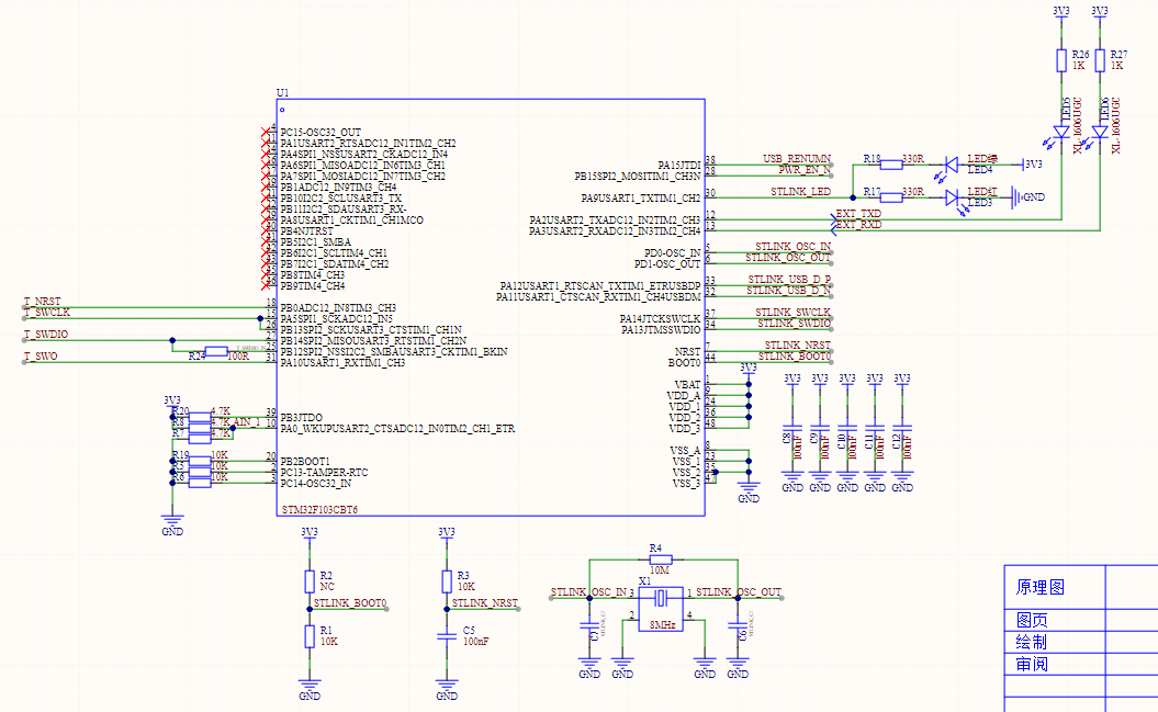
VI. Output Electronic Switch
: This design includes an output electronic switch. The external 3V3 is controlled by ST-Link to turn on/off. Note that this electronic switch does not have short-circuit protection; it is simply an electronic switch. It is recommended that you remove this component.
VII. Program Flowchart
: Include the program flowchart and upload the source code in the attachment.
VIII. External Interfaces and ESD Protection Devices
This design introduces the following interfaces:
1. STLINK's own SWD download interface. You need an STLink device to download the firmware to this downloader. If you don't have an STLink device, you can consider replicating the STLink device used in this design. However, you still need an STLink device to download the firmware to this downloader. If you don't have an STLink device, you can...
2. UART serial port
3. SWD and RST interfaces

IX. Precautions
Do not use AIR32F103CCT6. Do not use AIR32F103CCT6. Do not use AIR32F103CCT6. The original 32-bit is already cheap enough; it is recommended to use the original STM32F103CBT6.


 京公网安备 11010802033920号

 STK12C68-K35M


