Design Purpose: To learn Linux embedded development through the Taishanpai development board
. Project: A smart assistant based on the Linux embedded platform of the Taishanpai development board.
PS: This project mainly references the small mobile phone project document from the Taishanpai training camp
: 【Fat Girl Mobile Phone】Practical Project Materials - Feishu Cloud Documents (feishu.cn).
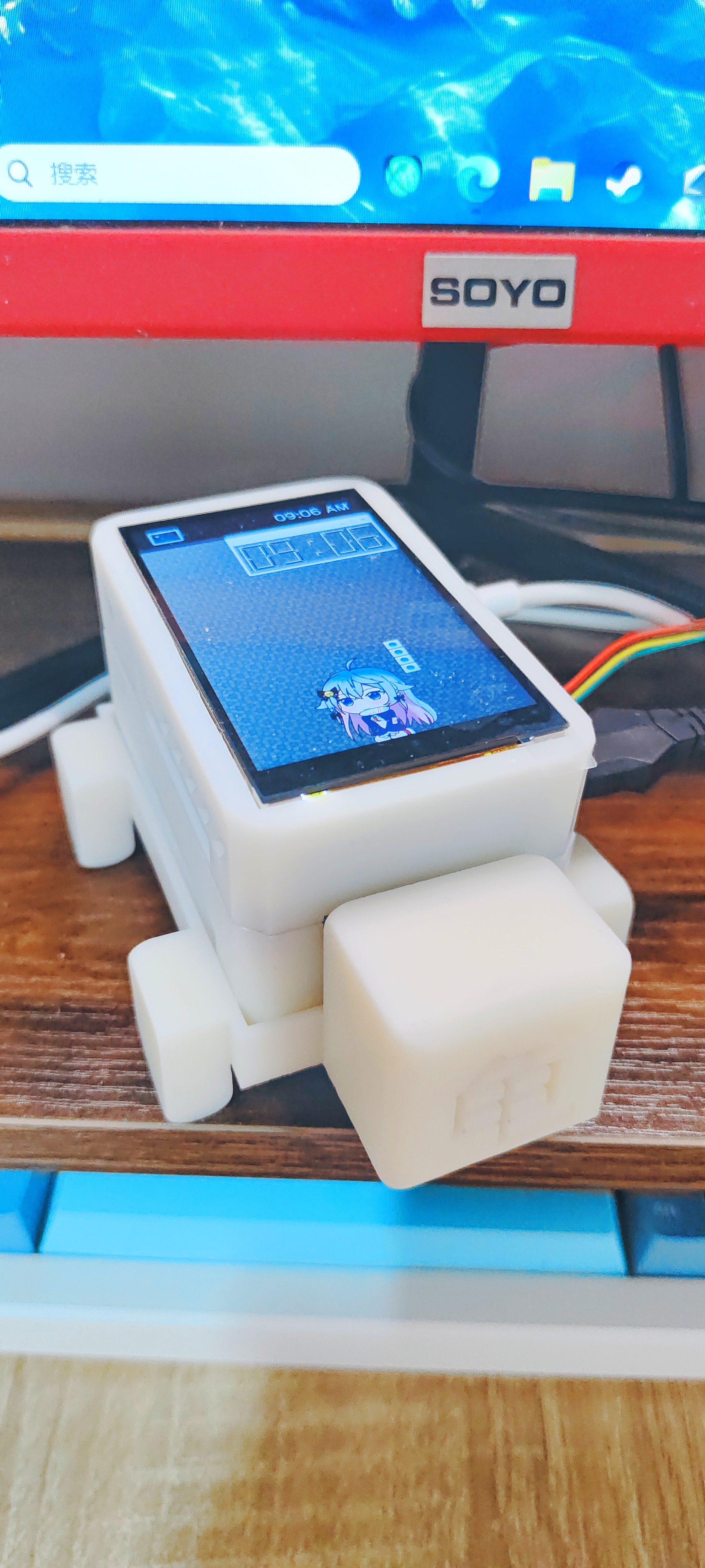
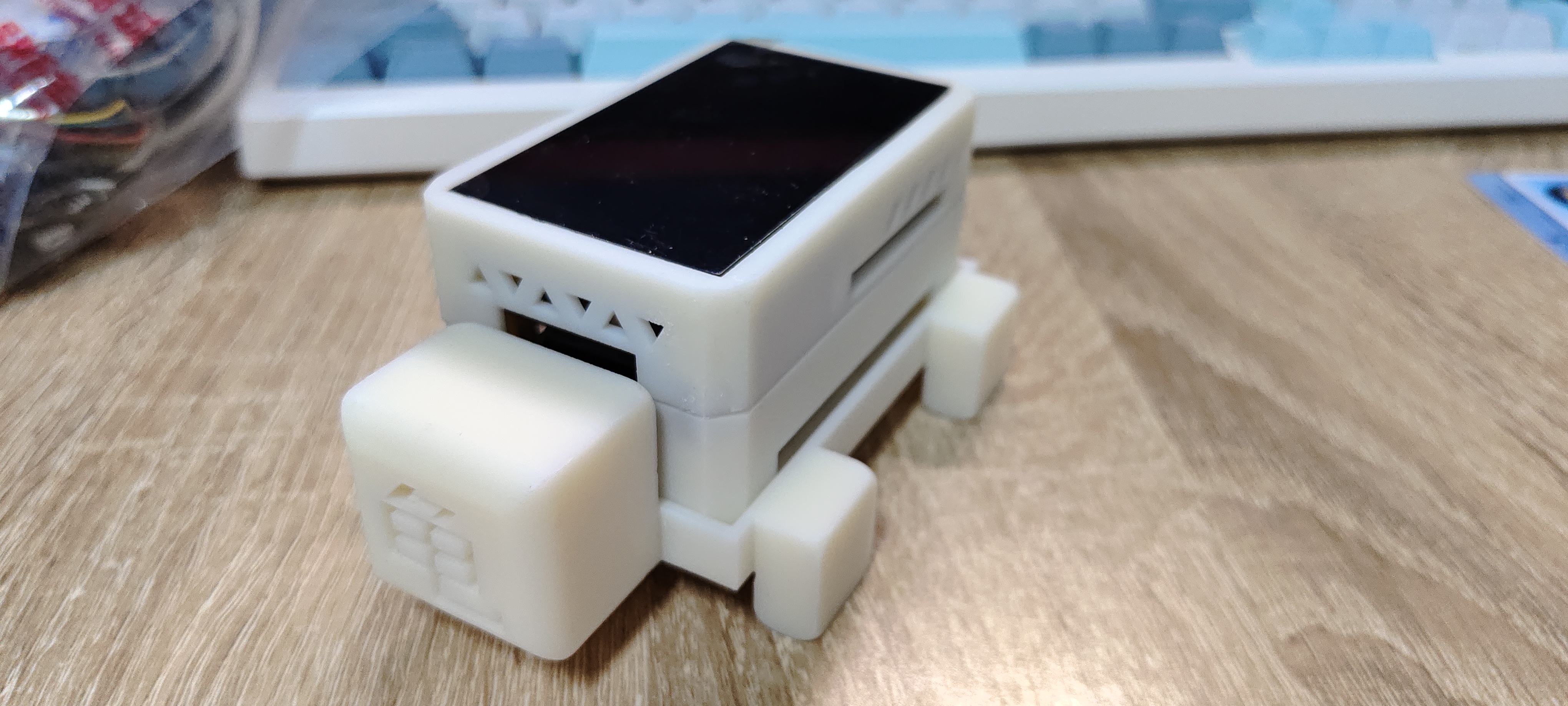
Product Showcase:
Circuit Hardware
Schematic Design:
① Core Board: Taishanpai development board of LCSC
② Top-level Application Expansion Board:
The top-level application expansion board is designed through the 40-pin GPIO, SPI and other peripheral channels brought out by Taishanpai. This expansion board,
designed for learning embedded application development under Linux,
uses a 40-pin header for direct connection to the Taishanpai device. The header connection is not very secure and requires some support.
Top-level application expansion board configuration:
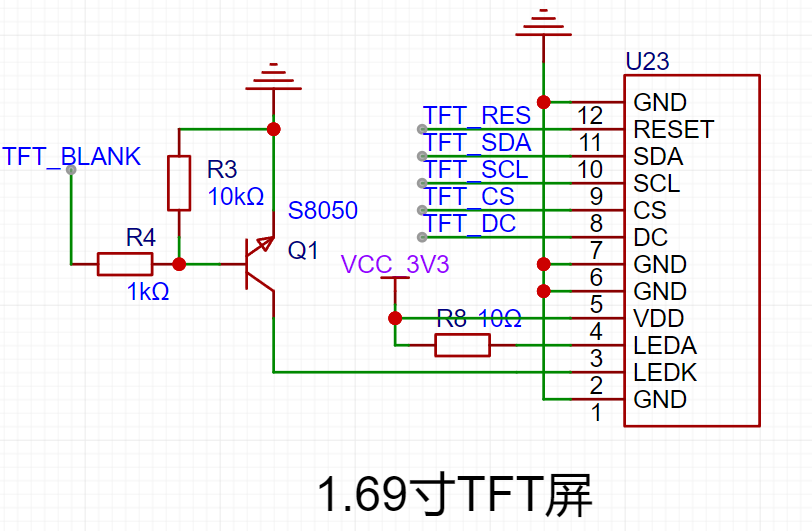
1. A 1.69-inch SPI interface TFT LCD screen, suitable for learning embedded screen development and porting LVGL, etc.
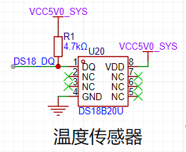
2. A DS18 temperature sensor, a classic temperature sensor for measuring ambient temperature.
3. An ADS1115 16-bit ADC converter using I2C communication for voltage acquisition;
only two channels are shown here.

4. A WS2812 RGB LED, easily controlled via GPIO, for colorful lighting.

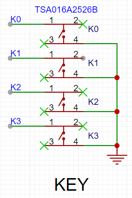
5. Four buttons.
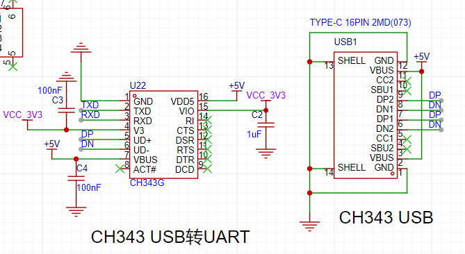
6. A CH343 USB-to-serial converter, providing access to the Taishanpai's RX and TX interfaces,
enabling serial-to-USB communication via the onboard CH343.
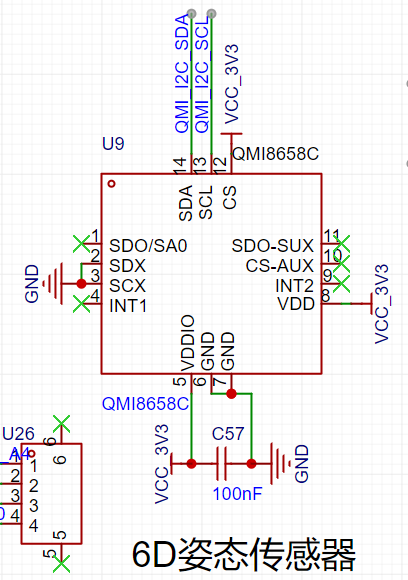
7. A QMI8658C 6D attitude sensor, designed with reference to the LCSC ESP32C3 practical development board
; the addition of an attitude sensor increases the device's physical playability.
8. A QMC5883L geomagnetic sensor. The design references the practical
design of the LCSC ESP32C3 development board, used for learning about geomagnetic sensors and implementing an electronic compass.

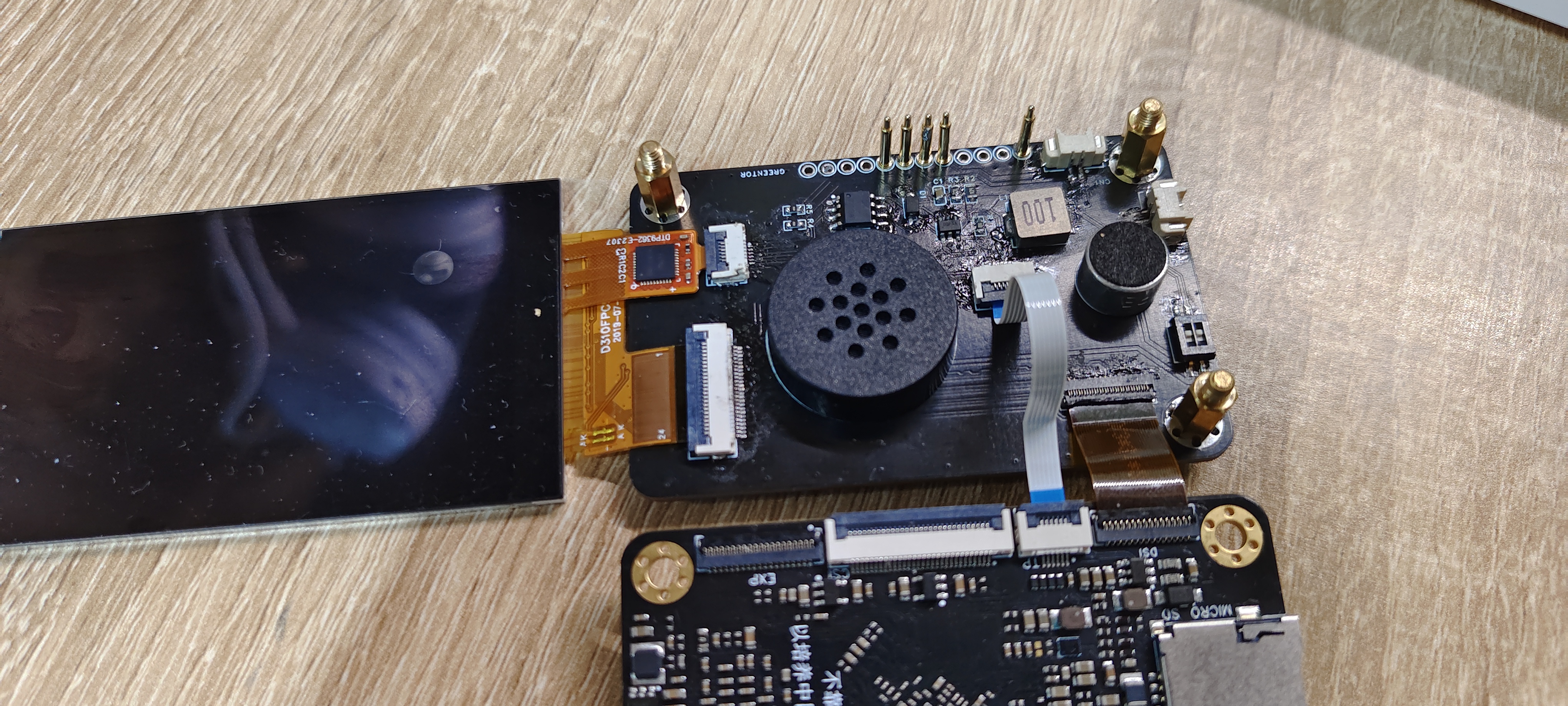
② Middle-layer media expansion board:
The middle-layer media expansion board references the 3.1-inch screen expansion board design from the training camp, with an onboard microphone and speaker.
It uses hexagonal studs and other supports to connect to the core board
. Top-layer application expansion board configuration:
1. 3.1-inch MIPI screen and touch interface, which can connect to the 3.1-inch MIPI touch screen of Daxianjia.

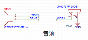
2. 3W speaker and microphone, which are led out from the contacts at the bottom of the Taishanpai core board via pogo pins
and connected to the onboard speaker and microphone.
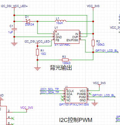
3. Screen backlight circuit. The screen is small, and the backlight should not be too large, so
the backlight interface of the core board is not used directly. The backlight circuit is designed to use I2C to control PWM to achieve stepless dimming.
③ Bottom-layer high-speed expansion board:
There is no design yet. Initially, it was planned to use the bottom-layer 39-pin expansion board designed by LCSC.
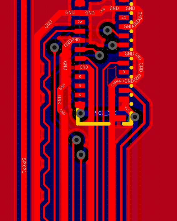
PCB Design:
Top Layer Application Expansion Board:
This expansion board does not contain high-speed signals or RF components, so the wiring was simple during layout.
Pay attention to the assembly during layout .
Middle Layer Media Expansion Board:
MIPI signal traces are wrapped with ground lines, and the length of differential lines is considered.
Hardware Sample:
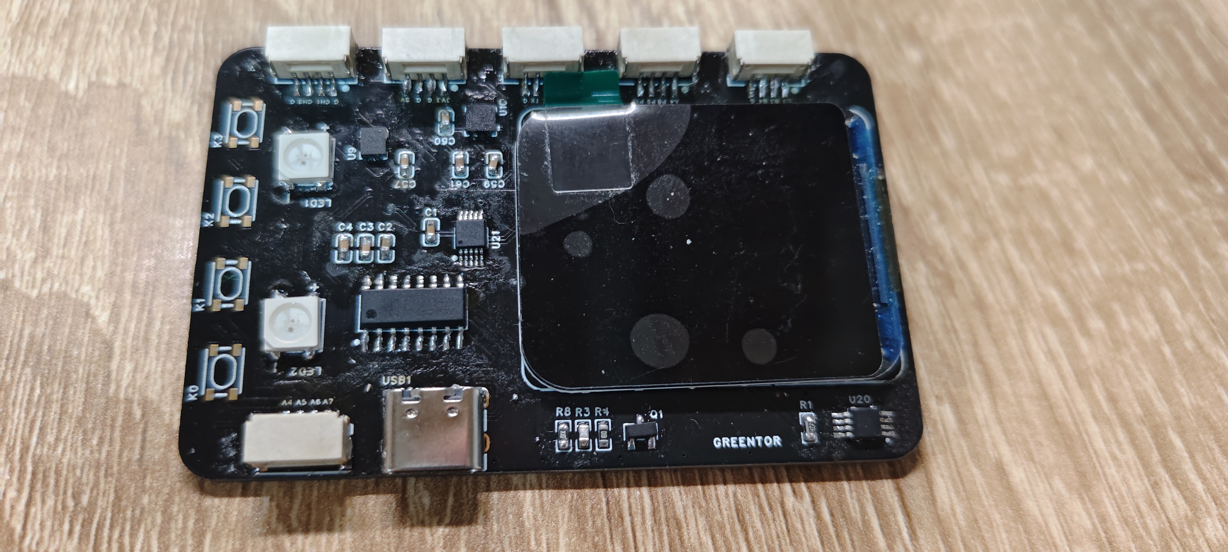
The appearance is poor because no board cleaner was used after soldering.
Soldering Challenges:
Soldering the FPC socket is challenging due to the very small pin spacing (0.3mm).
A soldering iron or hot air gun can be used for initial soldering, but a soldering iron is necessary to handle solder bridging.
Using ; it is very effective. Heating the soldering iron after soldering and then wicking the wick can largely resolve solder
bridging. For pin soldering, it is recommended to use a clamp. I used a direct insertion type. First,
heat the pads at the bottom, then apply a little solder. Insert the probe from above, straighten it, and then remove the soldering iron to
cool and fix it.
Shell
assembly:
The overall project has a top expansion board, so the shell design designed by Wu Gong from the training camp cannot be used directly. The shell
design uses ZW3D, and the size and other aspects are referenced from the design of the Fat Girl mobile phone shell. Because this project is to make
a smart assistant Guibao, the shell design uses turtle elements. The top cover, bottom cover,
and base are designed. The top cover and bottom cover are connected magnetically, referencing the video "
Magnetic Adsorption - The Combination of Box and Lid Part 2" on Bilibili.
The bottom cover and top cover have interface holes, and some decorations and heat dissipation and amplification holes are added
. The screen is directly fixed to the board and shell, all using friction damping.
The base is simply designed in the shape of a turtle and is not fixedly connected to the main body. The main shell can
be placed directly on it as a turtle shell.

Shell assembly:
M3 studs and screws are used for assembly. The pin and stud screw parameters are shown in the figure.

Assembly process:


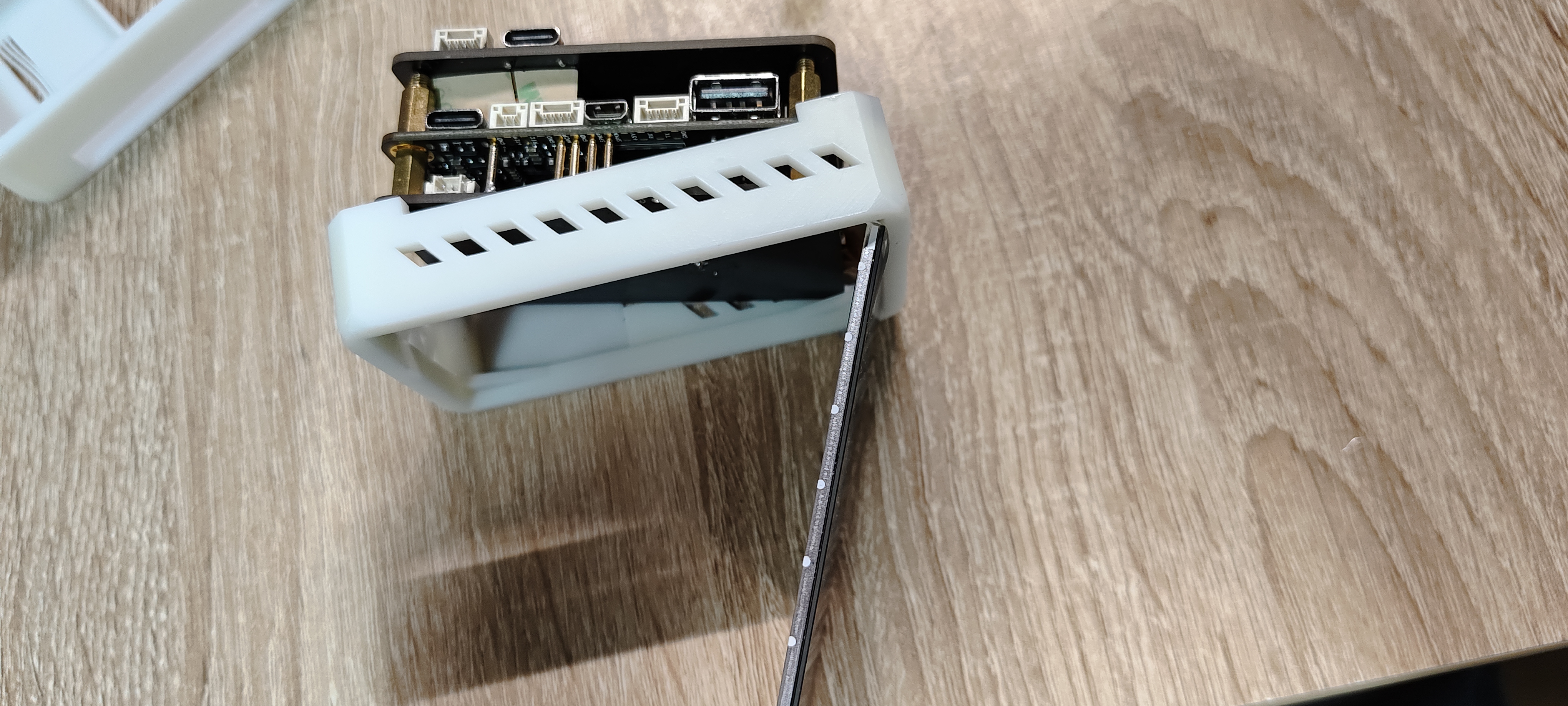
Note: Placing the screen directly in is not stable; it can be secured later with glue or double-sided tape, etc.
When placing magnets, be sure to distinguish the magnetic poles correctly, as it is very easy to fail.
Software part:
Screen driver design:
The screen, touch, and backlight drivers are all based on the learning and training camp project.
A bug was found when configuring the DSI device tree: Under the onboard Debian system, if the DSI uses VP1 output,
the screen cannot display the desktop normally; only a mouse pointer is shown. Touch works normally.
The screen displays normally after using vp0 output, and the cause is currently unknown.

QT Porting:
This project's smart assistant application is planned to be written in Qt. The program is designed using
Qt Creator on Windows, and cross-compiled on an Ubuntu virtual machine to generate
a Qt application usable on the Taishanpa Linux system. The
QT porting was set up according to the porting tutorial shared by experts in the document co-construction community. [Co-construction] Porting Qt5 - Feishu Cloud Documentation (feishu.cn)
Problems encountered when compiling QT:
1. Before compiling QT in Ubuntu, you need to download the dependency libraries; otherwise, errors are likely to occur later.
`sudo apt-get install bison build-essential gperf flex ruby python libasound2-dev libbz2-dev libcap-dev
libcups2-dev libdrm-dev`
The following are some common errors encountered
during the `make` compilation process: `aarch64-linux-gnu-gcc
: Command not found`.
After verification, it was found that adding the `aarch64-linux-gnu-gcc` folder environment variable as described in the tutorial
did not have an effect on `sudo` operations. For details, refer to
the error message "sudo make modules_install: aarch64-linux-gnu-gcc command not found _aarch64-linux-gnu-g++: command not found" in Ubuntu 20.04. The CSDN blog
suggests manually adding the path to the `/etc/sudoers` file. Afterwards, cross-compiling QT will succeed
. However, after porting the compiled QT library to Taishanpai and setting the environment variables, running the QT program
often encounters problems. Either the program doesn't respond, or it reports a Linuxfb error. My system is
Debian compiled with the SDK. After experimentation, I found that the QT program needs to have its permissions changed using `chmod` before running, and
`sudo` is required to start Linuxfb correctly
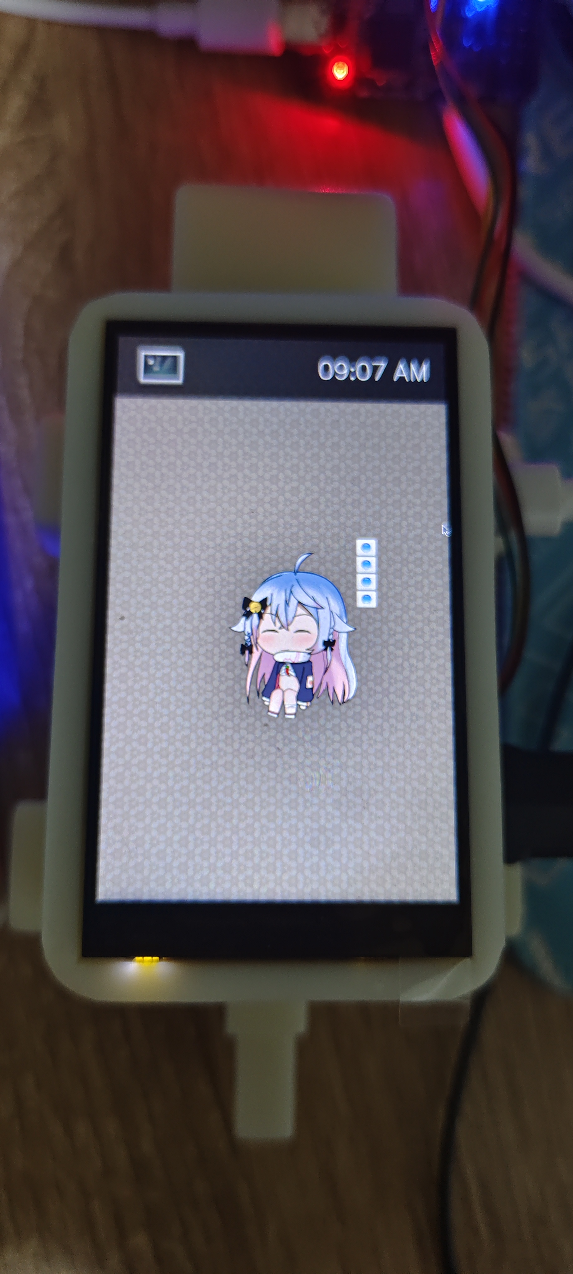
. After porting the compiled QT library to Taishanpai and setting the environment variables, running the QT program
works normally, but images are not displayed; only controls are shown. I spent a whole day searching online and tried
various methods. I've tried almost everything – checking image formats, changing environment variables, modifying Qt programs, etc. –
but it still failed. I hope some expert can provide a solution someday
. After considering various options
, since I couldn't get Qt running normally on the Debian-based Taishanpa system, and the tutorial documentation introduced
porting Qt to BuildRoot (which I had already compiled), I decided to give it a try.
I configured the Qt libraries in the BuildRoot menuconfig interface, selecting the necessary dependencies.
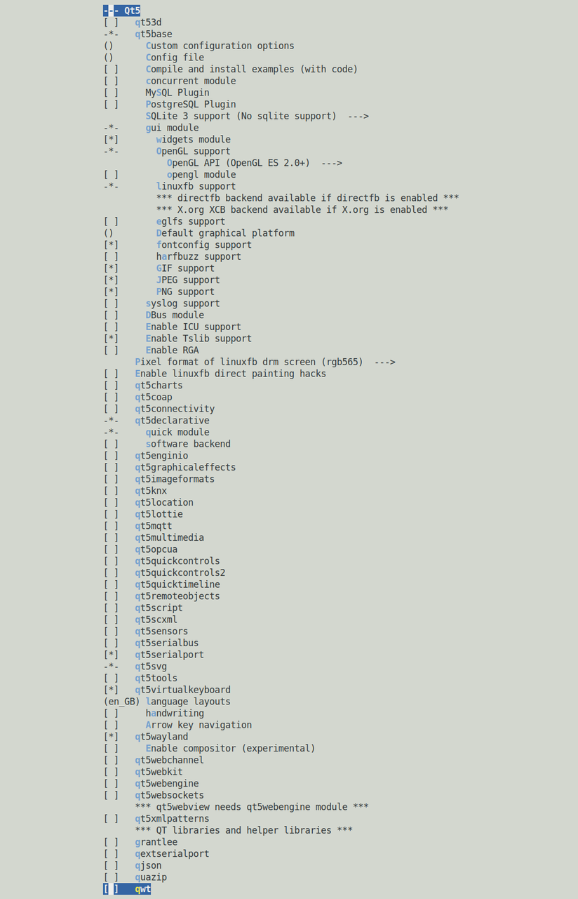
Using this interface for the first time, I was amazed by BuildRoot's power. After setting it up,
I recompiled everything, and the image was generated quickly. After burning it to the board, I used a mounted USB drive to transfer the cross-compiled Qt
executable to the board, and the program ran successfully! :-) Thus, my Qt Linux development officially began.
Qt Design:
TODO
Top-level Application Extension Board Driver:
TODO


 京公网安备 11010802033920号

 M38227E9MXXXGP


