The goal is to create a complete set of 3D printing peripheral equipment. Currently, we've only built the monitoring motherboard and the secondary curing machine. Future projects and corresponding programs will be open-sourced, and we welcome contributions of good ideas. This is a long-term project!
The secondary curing machine is not yet complete, but device interaction is.
Bilibili demo link: https://www.bilibili.com/video/BV1Fa4y1G76h/?vd_source=a1e9502e385d1bb03fa3ea7d653e93a3
A word of caution: Think twice before buying chips from Taobao; there are a lot of fakes! I bought three sets of MP3302 chips, a total of 15, and not a single one worked! They all burned out! I can only drive them using a display module I bought previously!

Table of Contents:
1. Introduction
2. Hardware Design
3. Software Design
4. Future Plans
1. Introduction
First of all, I would like to thank the following providers of materials. Without their sharing and contributions, many projects would only be empty dreams and not realized. I believe that in the future, our open source environment will get better and better, and even people like me who are not from a computer science background can play with it. After all, open source is about sharing and learning!

2. Hardware Design
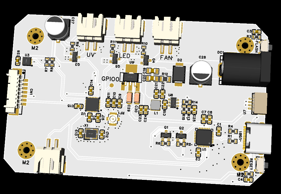
Monitoring Board:
The main controller uses ESP32 S3. Originally, I wanted to use a chip rather than a module solution, but considering the reproduction threshold for students, a module approach was adopted. It has an onboard 565RGB screen interface, constant current LED driver for screen backlight (because the existing LED constant current backlight chip was counterfeit, a module approach was used to drive the RGB screen), a passive buzzer, SHT30 temperature and humidity monitoring, and a serial port download speed of up to 4M.

Secondary Curing Machine:
It uses Espressif's ESP32C2 (i.e., ESP8684) chip. The advantages of this chip are: lower crystal oscillator frequency requirement, internal integrated FLASH, and lower peripheral circuit requirements. The design includes: one ESC input interface, one 12V UV lamp driver interface, one 12V LED lamp driver interface, one 12V fan interface, and one TVOC detector. It also includes a rotary screen serial communication interface (to be completed), allowing knob interactions to be fed back to the secondary curing machine. A DC-DC step-down design is used: the 12V is first stepped down to 5V to power the serial port chip, and then stepped down to 3.3V via an LDO to power the ESP32 and other chips.
3. Software Part
1. The monitoring board
is programmed using ESP-IDF, with LVGL as the graphical UI and double buffering. By modifying the ESP-NOW example, it can communicate via WIFI LAN/Bluetooth and allows for parameter setting/observation of various peripherals, making it the brain of this project. PlatformIO programming is used, through the underlying layer of PlatformIO, namely ESP-IDF5, which comes with various drivers for easy programming.
The monitoring board software consists of 5 parts.
1. Blynk:
I used a self-built server method. You can also use the main site's blynk, but there will be fewer controls, and you need to pay to get some firmware usage rights. If you use the self-built method, the controls you can use are similar to those on the main site, and the energy is still unlimited, so you can use the controls at will.
Next are the steps to install Blynk-server .
First, prepare a server in your local area network (because it is relatively easy to set up). I used ROCK5B, which is a smart device control system in my home, and I installed Ubuntu 20.04.
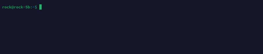
(1) Enter the terminal page, which is usually as shown in the figure below.
(2) Pull the blynk-server setup file. Here I put it on gitee.
Enter git clone https://gitee.com/lin_xiaoyan/blynk-local-server.git in the terminal. The following content
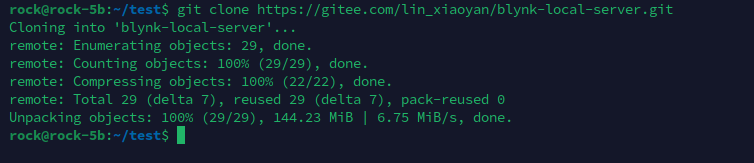
shows that the file has been pulled into your server. Enter the directory and use the ls command to view the contents of the directory. If it shows this, there is no problem.

(3)
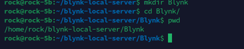
Upon first run, navigate to the directory and execute `java -jar server-0.41.16-java8.jar -dataFolder /home/pi/Blynk -serverConfig /home/pi/someFolder/server.properties`. You will encounter an error; don't worry, just follow the steps below.
Note that the first data directory address, `/home/pi/Blynk`, needs to be created using the `mkdir` command. Mine is `/home/rock/Blynk`, but this isn't fixed. You can also create such a folder in `blynk-server` and then use the `pwd` command to check its location and enter the correct directory.
The second directory address is the server's parameter settings directory. You need to create a `server.properties` file in the directory you set. I used vim to create it. In the `someFolder` directory, enter the following command: `vim server.properties`, and then type `:wq` to complete the file creation.

After creating the new directory and setting up the files, running `java -jar server-0.41.16-java8.jar -dataFolder /home/pi/Blynk -serverConfig /home/pi/someFolder/server.properties` will display the following screen
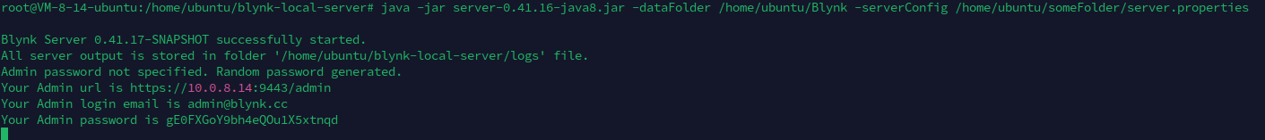
. Congratulations, you can start celebrating!
Open `https://10.0.8.14:9443/admin`. `10.0.8.14` is your internal network IP address. Enter the internal network address of your server to see the following interface. If you want to use it from the external network, you will need to perform internal network tunneling later.
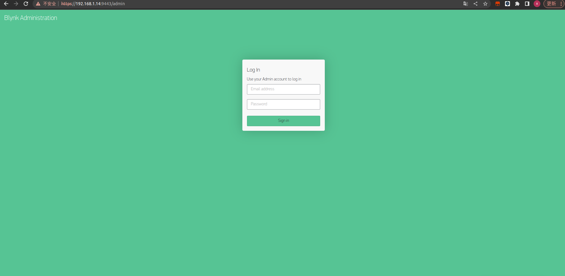
The email and password obtained from running the program above will appear in the following interface.

Our blynk needs to run in the background. Execute
`crontab -e`, which is the Linux task list;
select option 2 for scheduled command execution
. In vim, enter the following: `@reboot java -jar /home/pi/blynk-server.jar -dataFolder /home/pi/Blynk` (the directory here needs to be changed).

Execute
`sduo service cron reload` and
`sudo service cron restart`
. Then close the page.
Congratulations! You have completed the blynk-server setup!
For intranet penetration, I used Xiaomiqiu, and I would like to thank the expert Ciqiu for providing a free server!
First, register an account in the following tutorial (https://blog.xiaomiqiu.com/article/121).
Place the Xiaomiqiu client in your server directory.
My server architecture is arm64, so I saved the linux-arm folder to my server directory.
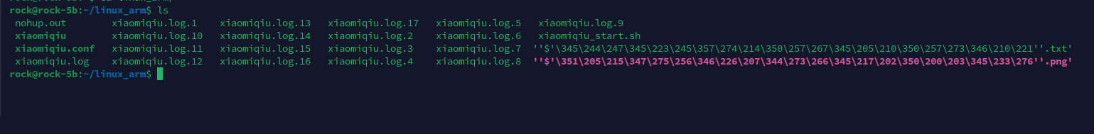
Use `vim xiaomiqiu.conf` to configure your Xiaomiqiu server.
It should look like this. I've hidden `auth_token` and `server_addr`.

You can find `auth_token` in the Xiaomiqiu console and

`server_addr` in the Xiaomiqiu server list. (See https://manager.xiaomiqiu.com/forum/question/questionDetail/39). If you're using a free server, you don't need to modify this.

After configuration, execute `./xiaomiqiu_start.sh` and press Enter.
To run it in the background, you need the `screen` software. On Ubuntu: `sudo apt-get install screen`; on CentOS: `yum install screen`.
Then `screen -S`
will bring up a new screen.
Next, execute `./xiaomiqiu_start.sh`, press Enter, and finally press Ctrl+A+D to switch to the next page.
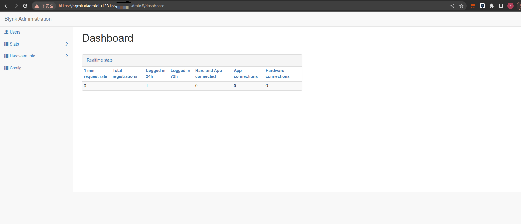
At this point, the blynk-server setup is complete. Log in to https://ngrok.xiaomiqiu123.top:assigned mapped port/admin and you should see the following interface. Congratulations!
Next, go to the mobile server configuration

and click the traffic light-like icon below. The page shown above will appear. Click "custom," enter `ngrok.xiaomiqiu123.top`, and the next line is the port number; fill in the mapped port.
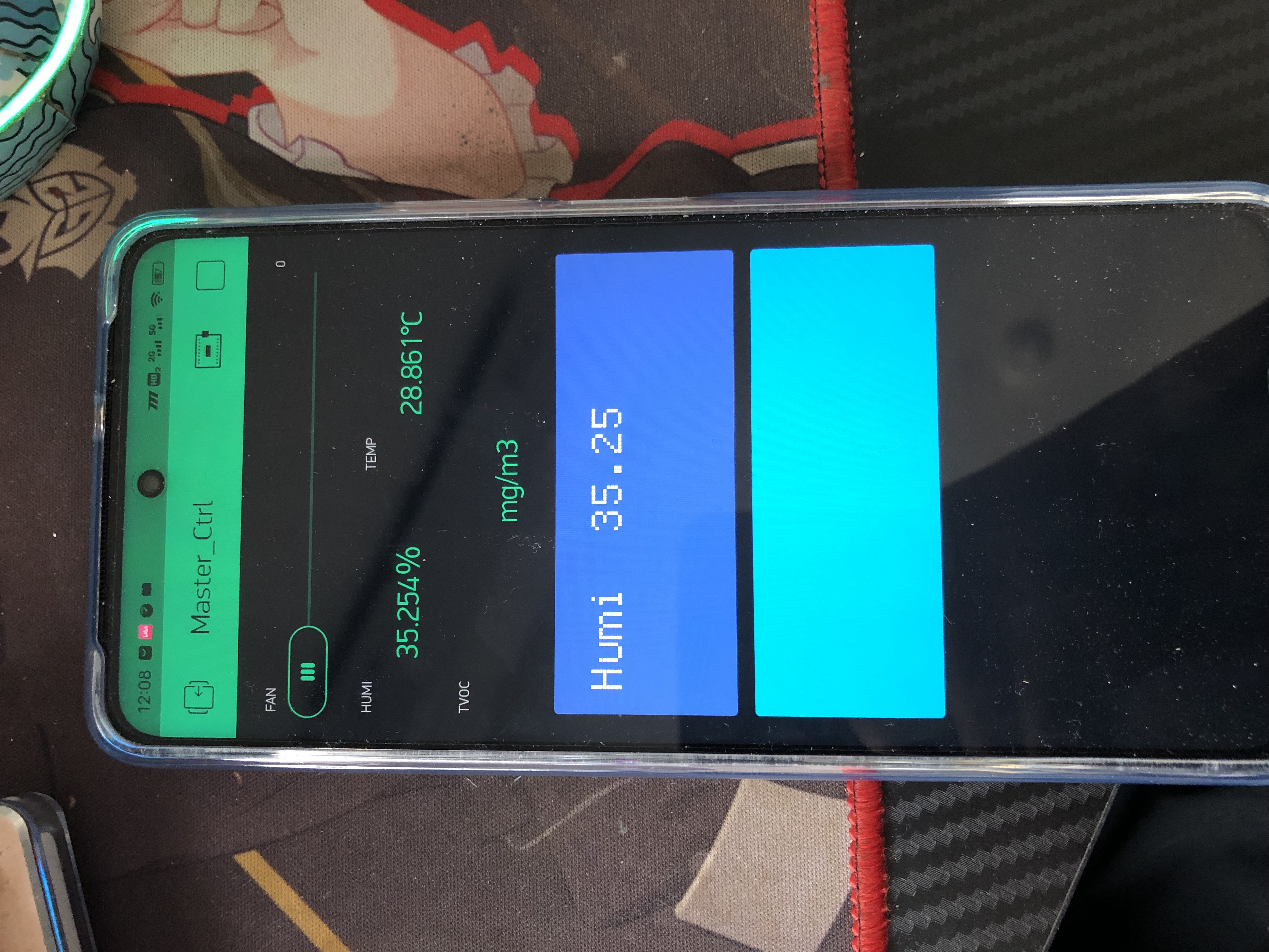
The following page will then appear! However, you need to create a new device on your mobile device. After that, in the blynk web interface, click User->admin@blynk.cc
and scroll down to see the following information
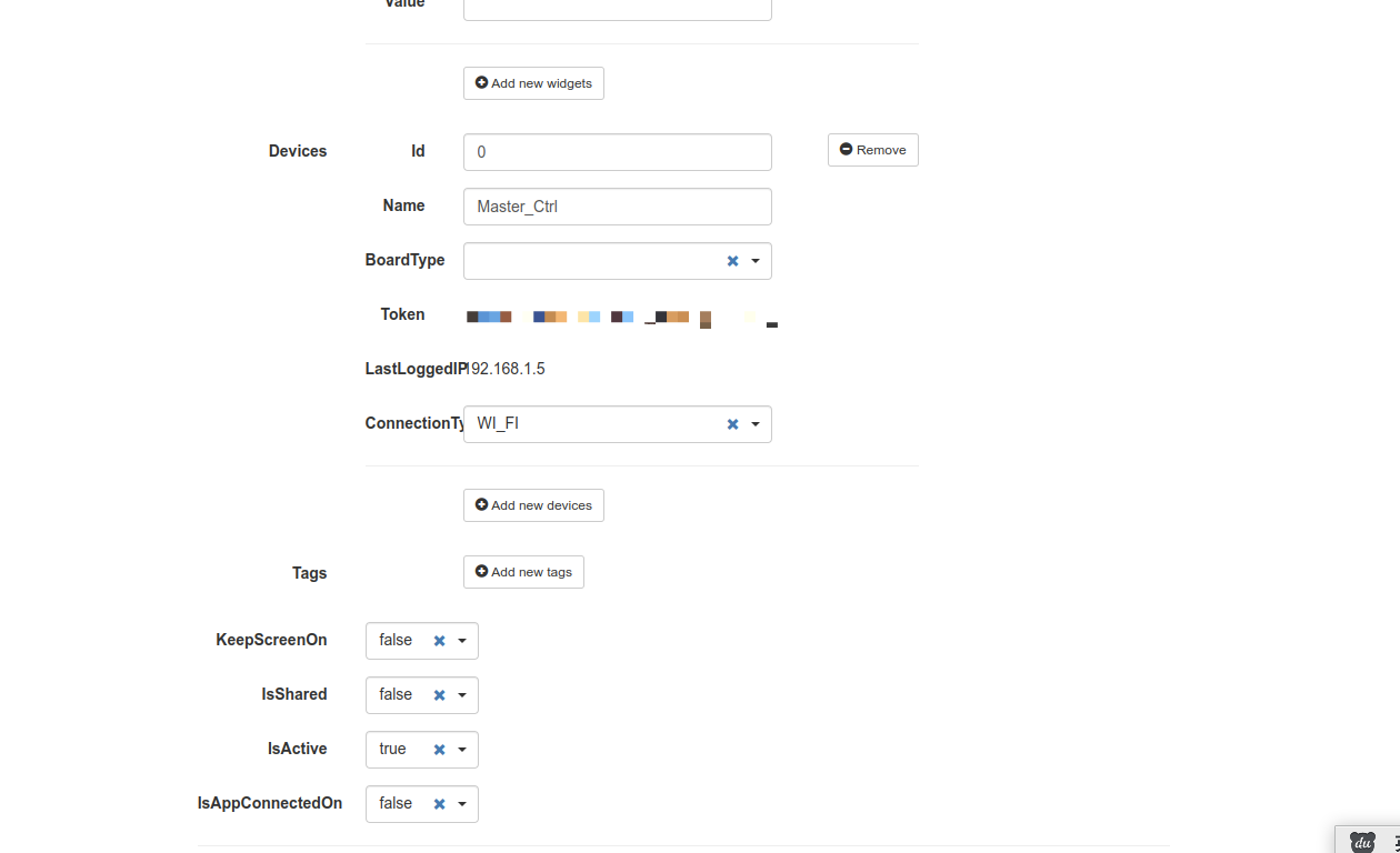
. We need to remember the Token.
Next, go to the device side to write the software

. You'll see that blynk has a `begin` function, which means initialization. The `BLYNK_AUTH_TOKEN` is the string of characters we just obtained from the web interface. `IPAddress` is your server's internal network address.
At this point, the blynk part is complete.
2. ESP-NOW
ESP-NOW is a wireless communication protocol defined by Espressif Systems that enables direct, fast, and low-power control of smart devices without a router. It can coexist with Wi-Fi and Bluetooth LE and supports multiple Espressif SoC series such as ESP8266, ESP32, ESP32-S, and ESP32-C. ESP-NOW is widely used in smart home appliances, remote control, and sensors.
ESP-NOW is a data link layer-based wireless communication protocol that simplifies the five-layer OSI protocol to a single layer. Data transmission does not require sequential transmission through complex layers such as network, transport, session, presentation, and application layers, nor does it require adding headers and unpacking at each layer. This significantly reduces stuttering and latency caused by packet loss during network congestion, resulting in faster response times.
ESP-NOW is easy to configure and simple to initialize. Communication can begin simply by configuring the send and receive callback functions.
We can see that the initialization process

begins with the initialization of `nvs_flash`, a requirement of the Wi-Fi library; its absence will result in an error.
The second is the initialization of `esp_now`, which can be called directly; an error will occur if the initialization is incorrect.
Then there are the registration of two callback functions: `OnDataSent1` and `OnDataRecv`. `OnDataSent1` represents the callback function executed after the send function `esp_now_send` (i.e., the program executed after execution), and `OnDataRecv` represents the callback function executed whenever data is received.

We can see that our receive callback function uses `memcpy` to copy the data from `incomingData` (i.e., the data sent by the sender) into the `Data` structure.
Generally, we only need to register this function. The above is the standard way to write a callback function.
Now let's look at the `Data` structure. It is actually called by both the send and receive functions, which is beneficial for the standardization of bidirectional data transmission.
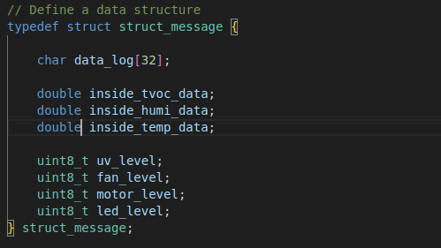
If you open the sending code, you'll see that their ESP-NOW transmit/receive structures are identical. This is what I mean by data standardization. Each segment of data within the structure must be the same, and their order and size in memory must also be identical. This standardization facilitates data retrieval and differentiation.
In the esp_now thread, I continuously send commands: `esp_err_t result1 = esp_now_send(broadcastAddress1, (uint8_t *) &Data, sizeof(Data));`. Upon receiving data, the receive callback function is called, thus completing bidirectional transmission between the two devices.
This is the main control board's transmit/receive data printout.

3. RGB interface 7-inch screen
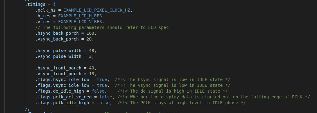
This section is an ESP-IDF example. Using PlatformIO has the advantage of being able to call both ESP-IDF examples and Arduino libraries because their underlying implementations are essentially the same. This method also applies to STM32, whose underlying implementation is CubeMX.
It's worth noting that the settings for these parameters must be consulted with the screen manufacturer; otherwise, the driver will fail.
4. LVGL
Initialization: There's not much to say about LVGL initialization. Use the ESP-IDF example: create a thread and call the refresh function.
My development tool for LVGL is gui-guider.
Here, I'll explain how to port the gui-guider code to our device .
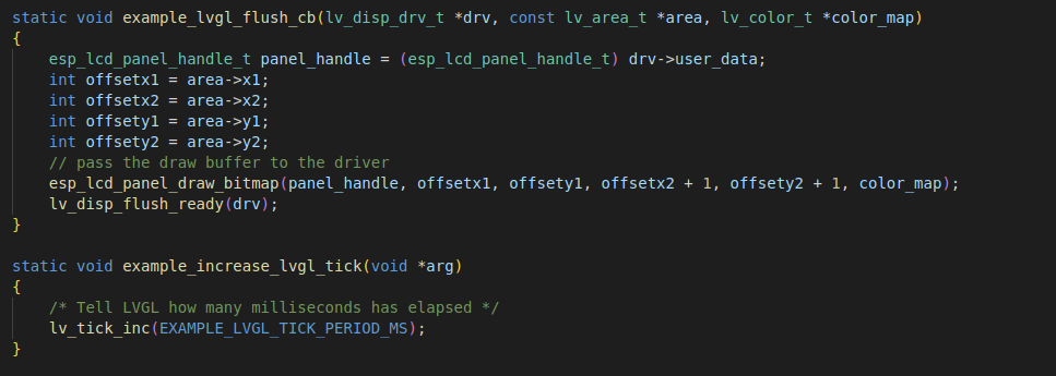
First, after developing the UI page, the generated C code will show several important files. Those
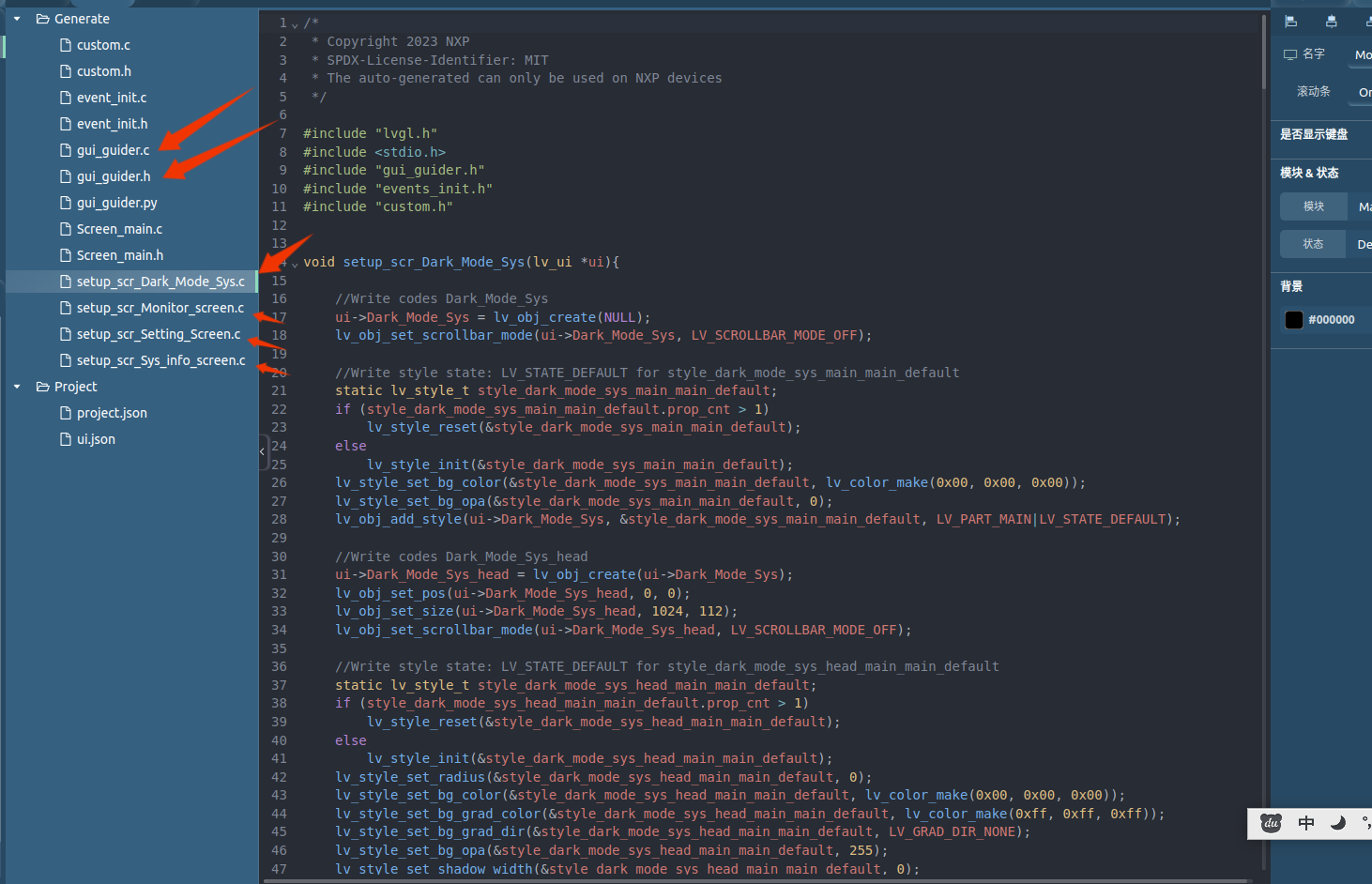
starting with `setup_scr` are your page settings, containing various object initialization functions. We only need to copy `gui_guider.c`, `gui-guider.h`, and the files starting with `setup-scr` to our device's code directory.
Some might ask, isn't `event_init.c` needed?
Actually, this is the LVGL event initialization function, but some controls don't have this event setting in gui-guider, so I manually added events without using the code in `event_init`.
After porting, this is the result.

5. PWM Generation
I used the ESP-IDF example program. Actually, Arduino is simpler; it only requires three steps: `ledcAttachPin(uint8_t pin, uint8_t chan)`, `ledcSetup(uint8_t chan, uint32_t freq, uint8_t bit_num)`, and initialization is complete. The duty cycle can be set using `ledcWrite(uint8_t chan, uint32_t duty)`, but I haven't yet investigated how to assign timers, so I used the ESP-IDF program.
The ESP-IDF PWM example program looks like this; it's not called PWM, but LEDC.
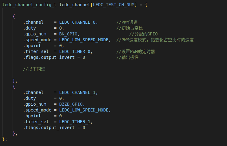
First, the channel is set up: configuring the PWM CHANNEL, assigning pins, output polarity, initial duty cycle, and PWM speed mode

. Next is the time base configuration; pay attention to the `duty_resolution` item, which will be discussed later.
Then, the time base and output channel are initialized.
At this point, the PWM initialization is complete. We can modify the duty cycle
using the functions
ledc_set_duty(ledc_mode_t speed_mode, ledc_channel_t channel, uint32_t duty);
and ledc_update_duty(ledc_mode_t speed_mode, ledc_channel_t channel);
but the value we set depends on the duty_resolution parameter.
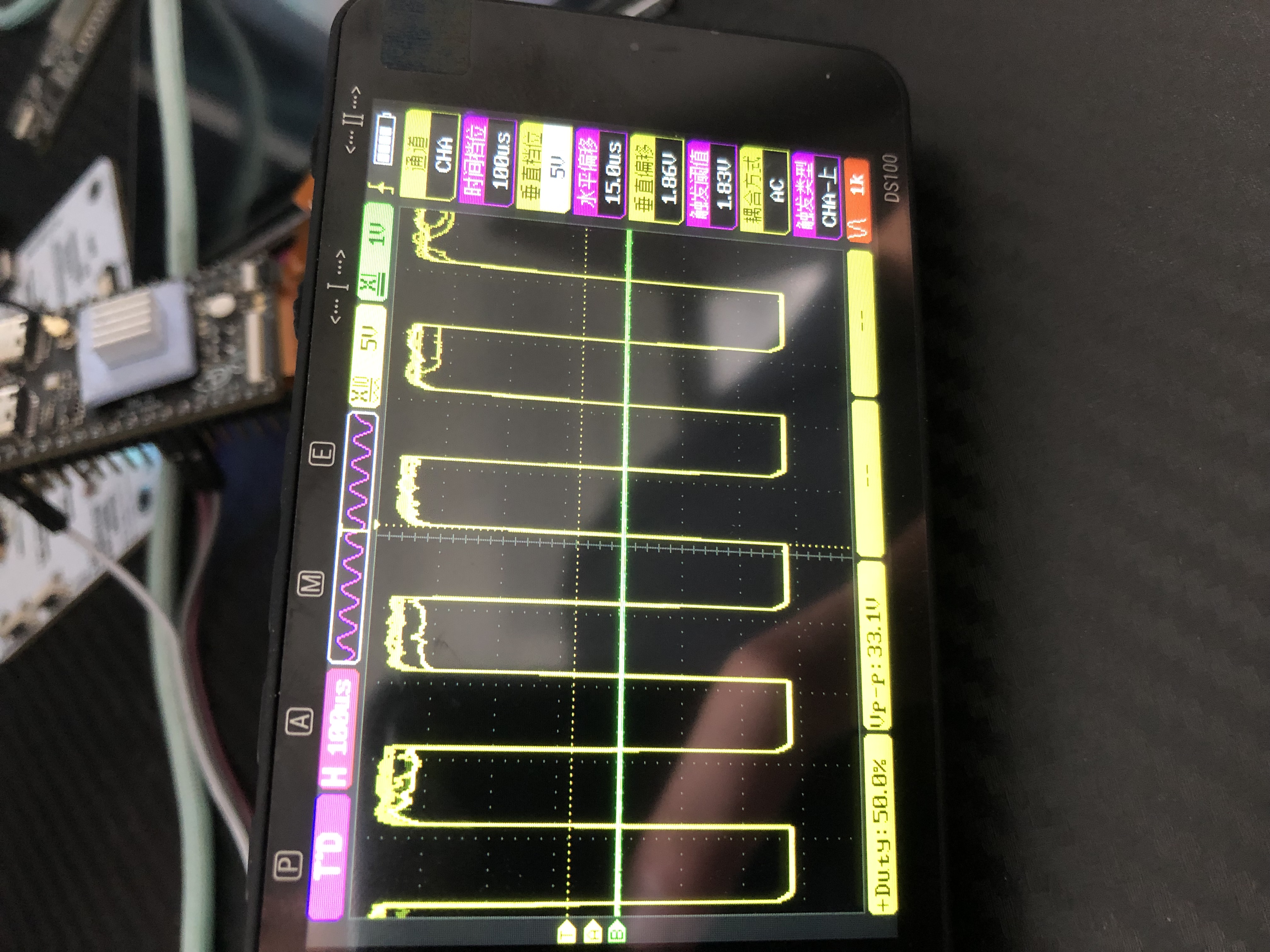
For example, here I use LEDC_TIMER_13_BIT, which means the resolution of this channel is 13 bits. When the duty cycle is 100%, duty = 2^(13)-1=8191.
Why is it called resolution? Because every time the duty cycle is changed, the amount of duty that can be changed increases, so the change of each duty cycle becomes more subtle (this can be seen on the LED).
When we want a 50% duty cycle, we need to set it to 50/100* [2^(13)-1] = 4095. The generated PWM wave is shown in the figure below.
6. The capacitive touch
uses the integrated driver of Teacher Chen Liang. Teacher Chen Liang is a master of screens. He wrote the famous GFX library. He also has an account on Bilibili. You can follow him~
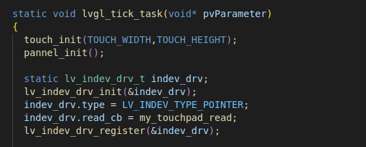
The lvgl registration touch driver callback function is written like this.
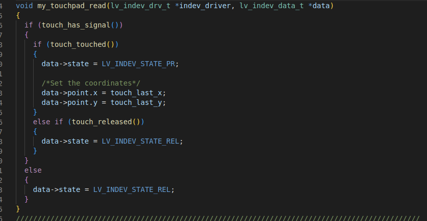
After
initialization, it can be written like this.
2. The secondary curing machine
is programmed using ESP-IDF. Through ESP-NOW, it can communicate with the monitoring board and send environmental parameters to the mobile terminal via blynk. Parameters can be set on blynk, and the main control board then sends them to the secondary curing machine, so that the parameters of the secondary curing machine can be modified. At the same time, information is sent to the monitoring board, so that the data on the monitoring board can be updated in real time.
The ESP-NOW and PWM drivers are similar to those on the main control board, so they will not be described in detail here.
The following section describes the drivers for the SHT30 and TVOC sensors.
1. SHT30 Temperature and Humidity Sensor:
An old friend, expensive and inaccurate.
Driven via I2C:
First, the I2C initialization route is

called. When it returns to the initialization state, ESP-OK indicates that initialization is complete. It is worth noting that there is already an I2C pull-up resistor here, so theoretically, it is not necessary to add another pull-up resistor.

The I2C write data is as above. Since our SHT30 also needs to be initialized, we can perform the SHT30 initialization settings through the above steps.
In the code, it can be written like this,
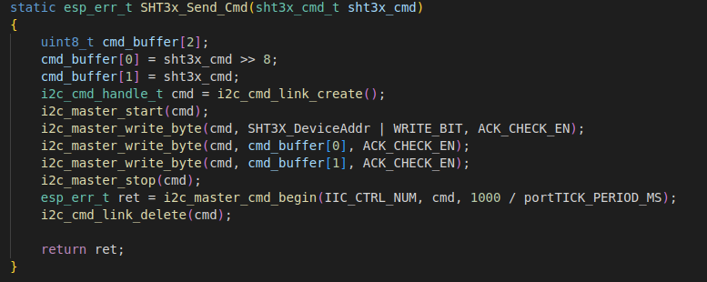
which is consistent with the sending steps on ESP-IDF.

Reading data is similar to writing data, except that the write function is replaced with the read function.

Finally, verification is performed to complete the process.

2. TVOC Sensor
Initialization: The initialization is done through the following steps.
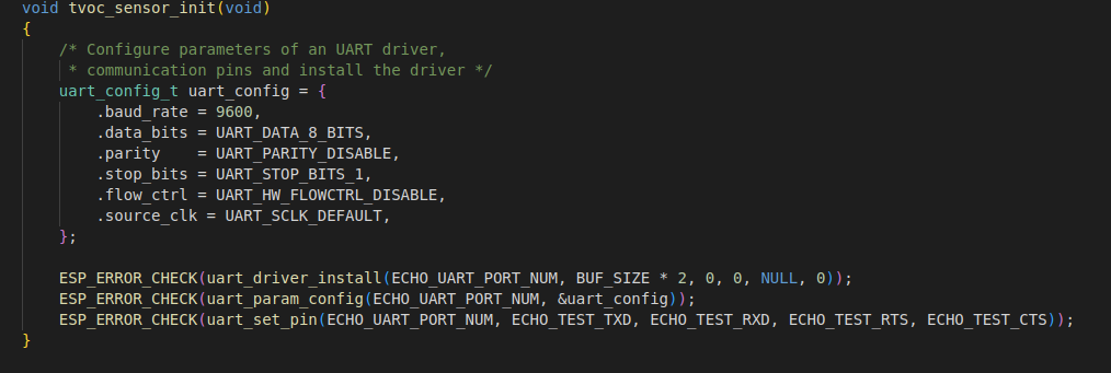
As you can see, first, UART settings are configured, then the driver is initialized, RAM space is allocated, and pin assignment is performed.

Since the ESP32 lacks a receive interrupt, we can only set it to receive data at regular intervals. The TVOC sensor sends data once per second, so we need to set a smaller receive period.

According to the manual, we need to find the header of the corresponding string in the received data characters. This is similar to the fingerprint module driver. First, the received data is stored in an array. Then, the strstr function searches for the address pointer of the string below the header. The address pointed to
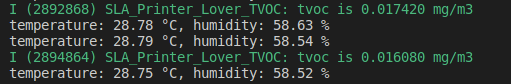
by this pointer is the address of our TVOC data. The verification function yields our TVOC data string.
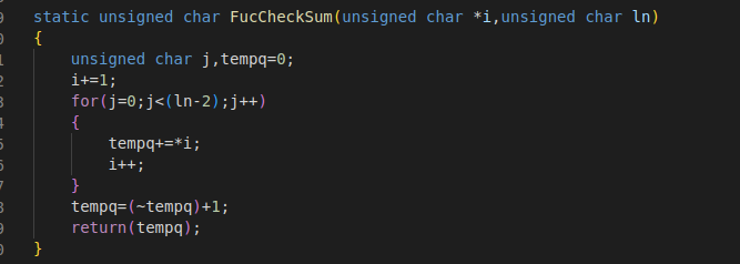
Using the algorithm in the manual, we can then derive our TVOC data.
3. FDM Environment Acquisition (Future Plan)
To be uploaded
4. Photopolymer Cleaning Machine (To be integrated)
4. Future Plans
1. Due to a 30-day internship, the FDM monitoring of the cleaning machine was not completed. I will add these two parts after finishing my graduation thesis. The cleaning machine uses neodymium magnets and a motor for rotation, and the effect seems acceptable.
2. Research on SPIFFS+LVGL for data storage. Currently, there is no data storage function; this will be added later.
3. 3D printed casing is now online!
4. Since the ESP32-S3's RGB driving of a 7-inch screen is already at its limit, we will consider using the Allwinner T113 for driver
progress tracking later.
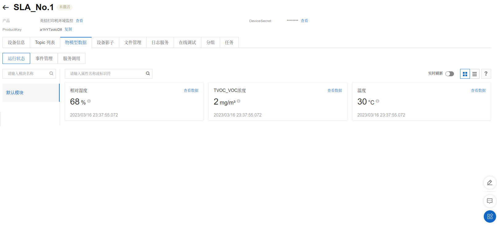
March 16th: Basic UI graphics are nearing completion; Alibaba Cloud devices have been connected.


March 17th: SmartConfig network configuration completed; no need to manually enter the WIFI password in the program.

March 19th: LED stepless dimming and TVOC sensor functions completed.


 京公网安备 11010802033920号

 2SC3703


