1500W PWM based inverter circuit
Source: InternetPublisher:风向西瓜 Keywords: PWM inverter inverter circuit Updated: 2025/03/11
In this article, a basic but fairly efficient 1500W PWM based inverter circuit can be examined. This design utilizes very common parts to accomplish a powerful SPWM type inverter circuit.
Main Specifications
Power output: 500W to 1500W adjustable
Output voltage: 120V or 220V, depending on transformer specifications
Output frequency: 50Hz or 60Hz as required.
Working power supply: 24V to 48V
Current: Depends on MOSFET and transformer ratings
Output waveform: SPWM (can be filtered to achieve pure sine wave)
design
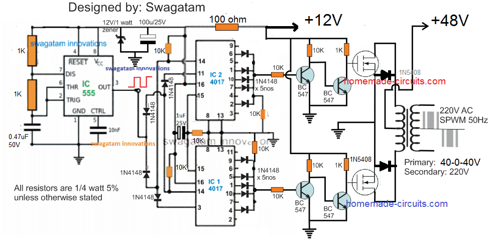
The proposed 1500 Watt PWM sine wave inverter is designed using extremely basic concept by using several IC 4017 and a single IC 555.
In this concept, the timing logic of IC 4017 output is configured by selecting and skipping subsequent pinouts so that the resulting timing produces a nice SPWM as if turning on the connected MOSFETs and transformer.
The complete schematic can be visualized in the following figure:
The working principle of the inverter can be understood from the following explanation:
Circuit Operation
It can be seen that two IC 4017 are cascaded to form an 18 pin sequencing logic circuit where each negative pulse or frequency from IC 555
produces a shifted output sequence on each indicated output of the two 4017 ICs, from pin #9 of the upper IC to pin #2 of the lower IC, when the sequence is reset to restart the cycle.
We can see that the output of IC 4017 is intelligently tapped by skipping and combining groups of output pinouts so that switching to the MOSFETs gives the following waveforms:

As per the waveform, by eliminating the concerned pinouts of the IC, it can be seen that the start and end sequences are skipped, similarly the second and 6th pinouts are also skipped whereas the 2nd, 4th, 5th, 6th pinouts are connected so as to achieve SPWM like pulse form on the output of both 4017 ICs.
Here we can see that the initial block is eliminated so that the SPWM waveform can match the initial lowest RMS value of an actual sine wave, the next two alternating blocks mimic the average rising RMS within the sine wave, and the middle 3 blocks attempt to replicate the maximum RMS of an exponentially rising sine wave.
When the above PWM format is applied to the gate of the MOSFET, the MOSFET alternately performs transformer primary switching with the same switching format in a push-pull manner.
This forces the secondary to synchronously follow the induction pattern with the same waveform, ultimately resulting in the creation of the desired AC
220V with the above mentioned SPWM waveform pattern. A properly sized LC filter on the transformer output winding may eventually allow for a perfect sinusoidal waveform on the secondary side.
Therefore, when the resulting output of this SPWM is filtered, it should hopefully result in a replica of a sine wave output, which is probably suitable for operating most electrical appliances.
Oscillator Stage
Here a common IC 555 astable is used to create the required clock pulses to power the cascaded 4017 ICs and enable sequential logic on their output pin configuration.
R2, R1, and C555 associated with IC 1 must be calculated accurately so that pin #3 can produce a frequency of approximately 50 Hz at approximately 900% duty cycle. The 900 Hz output becomes necessary so that the sequencing of the 18 IC's 4017 pinouts causes the BJTs to trigger at 50 Hz on both channels and chop a single 50 Hz module at approximately 150 Hz.
About MOSFET and Transformer
The MOSFETs and transformer of the above 1500 Watt SPWM inverter circuit are the two elements that determine the total power output. To get 1500 Watt output, make sure the battery power is no less than 48V at 500 Ah, while the transformer can be around 40-0-40V/40 amps. If a 4620V battery is used, each MOSFET can be an IRFS48TRLPBF, and a pair of these MOSFETs in parallel are required on each channel to ensure that the full 1500 Watt power is properly delivered at the output.
- How to use LM317 as a switch to turn power load on and off
- LM338 adjustable voltage regulated power supply circuit diagram
- Methods for Suppressing Conducted Radiation in the FM Band
- How to improve the accuracy and precision of power supplies through low frequency thermal noise?
- How about the boost converter TPS61299?
- TPS274C65 helps reduce downtime and increase productivity in 24 VDC power distribution plants
- How to Make a Soft Latch Circuit
- Schematic diagram of car cigarette lighter to USB power port
- Cleverly use the electronic ballast of waste energy-saving lamps as power supply transformer
- Boost drive circuit composed of RT8450
- How current transformer works
- The difference between switching power supply and ordinary power supply
- Power supply circuit design optimized for digital light projectors
- Power circuit a composed of intelligent thyristor modules
- Solar power circuit
- EPSON PHOTO 830U printer power circuit
- Output 12V-10A power supply circuit
- Three-terminal PWM switching power supply-PWR-TOP200 series and applications 02
- pwm position true flow servo circuit
- 50A 150VPWM DC drive circuit


 京公网安备 11010802033920号