Homemade AA battery charger circuit diagram
Source: InternetPublisher:张小哥 Keywords: Battery Charger Updated: 2025/03/07
Homemade AA battery charger circuit diagram (I)
The charger circuit shown in the figure is simple, practical and easy to make. The 220V AC is stepped down by the 9V transformer B, and after full-wave rectification, the two No. 5 batteries in series are slowly charged. When the positive pole of D. is the positive half cycle of the AC, D. is turned on and rectified, while D. is turned off, and only the two No. 5 batteries on the top are charged. When the positive pole of D. becomes the negative half cycle of the AC, the positive pole of D. is the positive half cycle of the AC, D. is turned on and rectified, while D. is turned off, and only the two No. 5 batteries on the bottom are charged. In fact, this circuit charges the upper and lower groups of batteries alternately.
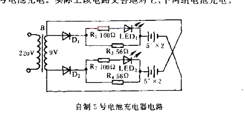
R, R, R, and R are current limiting resistors, and light emitting diodes LED and LED indicate charging status.
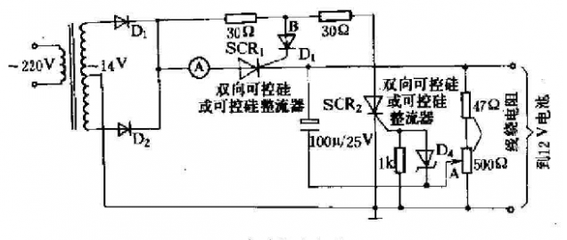
Homemade AA battery charger circuit diagram (II)
The figure below is a battery charger that can automatically terminate charging. It is simple and easy to make. The input AC voltage is applied to the thyristors SCR1 and SCR2 after full-wave rectification. The voltage of the battery being charged is much lower than 12V. Assume that the voltage at the center tap point A of the 500Ω voltage regulator is VA. Since the voltage regulator diode D4 is reversely connected, when VA is less than the voltage regulator voltage indication of D4, SCR2 does not conduct, forming an open circuit state. The voltage Vb at point B is large enough and synchronized with the AC full-wave voltage applied to SCR1. SCR1 conducts, and after filtering by a 100uF capacitor, a relatively stable DC output is obtained to charge the battery being charged. As the voltage of the charged battery increases, Va is greater than the voltage regulator voltage value of D4, and is sufficient to make SCR1 turn on. Vb is much smaller than the cathode voltage of SCR1, and SCR1 will not conduct and stop charging the battery. In order to ensure that the circuit terminates charging only after the battery is fully charged, a fully charged battery should be connected to the output terminal in advance, and the 500Ω potentiometer should be adjusted to adjust the termination point of the circuit.
- TL783 voltage regulator protection circuit diagram
- How to ensure the stable performance of SSD when the voltage is unstable?
- Build a simple buck-boost regulator and test it on a breadboard
- Brief Analysis of the Working Principle of AC Voltage Stabilizer Circuit
- ISO113 circuit that can reduce power consumption
- BA6104 five-digit LED level meter driver integrated circuit basic application circuit
- The constant current source composed of two transistors can drive high power
- LED rechargeable flashlight circuit diagram
- Switching power supply circuit composition and function introduction of each part
- Voltage-current converter constructed with XTR110
- Alkaline battery charger circuit diagram
- 60 watt laptop battery charger circuit
- Nickel-cadmium battery charger circuit diagram
- Fully automatic cadmium nickel battery charger circuit
- Dry battery charger circuit
- Wind energy battery charger circuit
- Nickel-cadmium battery charger circuit with voltage and current limiting function
- Voltage-limiting nickel-cadmium battery charger circuit diagram
- Battery charger circuit diagram with discharge function
- Solar battery charger circuit diagram


 京公网安备 11010802033920号