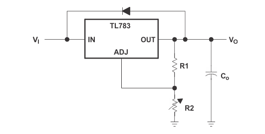
TL783 voltage regulator protection circuit diagram
Source: InternetPublisher:走马观花 Keywords: Voltage regulator protection circuit Updated: 2025/02/25
The TL783 regulator includes built-in protection circuits capable of protecting the device from most overload conditions encountered in normal operation. These protection features include current limiting, safe operating area protection, and thermal shutdown. These circuits protect the device only in the event of an occasional fault. Continuous operation in current limiting or thermal shutdown modes is not recommended.
The internal protection circuitry of the TL783 protects the device up to the rated voltage as long as certain precautions are taken. If Vl is turned on momentarily, transients exceeding the maximum input rating may occur, damaging the regulator. Typically, these are caused by lead inductance and bypass capacitors causing ringing voltages at the input. In addition, when a rise time exceeding 10 V/ns is applied to the input, the parasitic npn transistor in parallel with the DMOS output may turn on, causing device failure. If the device is operated above 50 V and the input is turned on instead of ramping on, low-Q capacitors such as tantalum or aluminum electrolytic capacitors should be used instead of ceramic, paper, or plastic bypass capacitors. A Q factor of 0.015 or higher usually provides sufficient damping to suppress ringing. Usually, there will be no problem if the input voltage is allowed to rise upward through the action of the AC line rectifier and filter network.
Likewise, when a momentary short circuit is applied to the output, both ringing and excessive fall times can result. Tantalum or aluminum electrolytic bypass capacitors are recommended to eliminate this problem. However, if large output capacitors are used, and the input is shorted, it may be necessary to add a protection diode to prevent the capacitor from discharging through the regulator. The amount of discharge current generated depends on the output voltage, the size of the capacitor, and the fall time of Vl. Protection diodes are only required for capacitor values greater than:

Always be careful not to plug the regulator into a live outlet. Turn off the power supply before removing or inserting the regulator.
- Benefits of Wide Bandgap Technology for Power Converters
- Step-down power supply for driving relays
- LED rechargeable flashlight circuit diagram
- Switching power supply circuit composition and function introduction of each part
- Principles and precautions of active discharge circuit
- Dual forward converter schematic diagram
- Boost drive circuit composed of RT8450
- Dynamic power supply for power amplifier controlled by thyristor
- LM317 regulated power supply
- Mc34063 MP3 Switching Charger
- Leakage current protection circuit
- Relay protection circuit a
- Low voltage circuit breaker protection circuit a
- Longitudinal differential protection circuit
- Transformer gas protection circuit
- Water inlet motor protection circuit
- Short circuit and overvoltage protection circuit for large current regulated power supply
- Regulated power supply overcurrent protection circuit 2
- Single board computer overvoltage protection circuit
- Asynchronous generator capacitor overvoltage protection circuit


 京公网安备 11010802033920号