What are the design methods of adjustable power supply circuit?
Source: InternetPublisher:狂妄火龙果 Keywords: Power supply circuit design power supply circuit adjustable power supply circuit Updated: 2025/03/04
With the abundance of electrical appliances and the increase in electricity usage sites, conventional output voltages can no longer meet the requirements of diverse usage scenarios. Especially when the distance between the power-consuming equipment and the power-supply equipment is far, the voltage drop caused by the wires in the middle cannot be ignored. It will reduce the actual supply voltage of the load and affect the quality of electricity use. In order to take into account all electricity users, power supplies with adjustable outputs came into being.
Common methods
At present, the conventional adjustable power supply replaces the stable resistance with an adjustable resistance in the voltage sampling loop to achieve the function of adjustable output voltage. In the adjustable voltage setting, the strategy of "upper bias range ≥ lower bias range" is generally followed. After all, if the voltage is high, the back end can reduce the voltage by routing and other methods. But if the voltage is low, it is really low, and a good cook cannot cook without rice.
In a general voltage sampling circuit, the resistor is replaced with an adjustable resistor. There are two ways to achieve the function of output voltage adjustment.
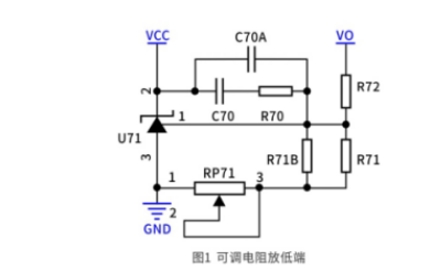
(1) When the adjustable resistor is placed at the lower end
The change of adjustable resistance affects the sampling current, which in turn affects the output voltage. The parameter calculation design is slightly complicated, and the resistance value is large, which makes the selection difficult. The change of adjustable resistance will affect the sampling current. To ensure the regulation rate performance, we generally set the sampling current to be 100 times larger than the current flowing into the reference pin of TL431 to achieve controllable performance.
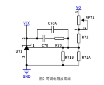
(2) When the adjustable resistor is at the high end
The change of adjustable resistance directly affects the output voltage, the parameter design is more intuitive, and the slope change is small. However, since the high-end resistance participates in the product loop adjustment, when adjusting the output voltage, the loop gain and phase margin of the product will change. The changes of these two are nonlinear, which will increase the uncertainty of the product. At the same time, when an overvoltage disturbance occurs at the output end, the high-end adjustable resistance will bear some stress, which will reduce the reliability of the adjustable resistance in the long run and affect the product life. Therefore, the high-end resistor package we put is generally 0805 or above, and the low-end resistor package is 0603 or below.
Circuit Comparison
Taking 24V output as an example, Figure 3a is a comparison of the slopes of the two when the sampling circuit parameters are similar. It is obvious that when the adjustable resistor is placed at the low end, the output voltage is greatly affected by the change in resistance value, and the slope changes monotonically. When the adjustable resistor is placed at the high end, the output voltage is less affected by the change in resistance value, and the slope remains almost unchanged. If the high-end circuit wants to achieve such a wide voltage change, the resistance of the sampling circuit needs to be reduced at the same time, and the result is shown in Figure 3b.
In summary, since high-end design will cause product reliability problems and make loop design more difficult, the adjustable resistor is generally designed at the low end.
Circuit optimization and advantages
However, although these two circuits are simple, after the adjustable resistor is abnormally disconnected, the product will open the loop, and the output voltage will rise without limit, causing overvoltage damage to the back-end product. For this reason, it is necessary to add additional output overvoltage protection limits. At the same time, because mechanical adjustable resistors are greatly affected by temperature, the thermal expansion and contraction of the device at high and low temperatures will cause the contacts to shift, resulting in output voltage fluctuations and voltage temperature drift problems. If the adjustable resistor is not restricted, the temperature drift of the resistor value will affect the output voltage, and in severe cases, the voltage accuracy will drop. The low-end R71 and R71B and the high-end R72 above are one of the series limiting methods.
In addition to series connection, parallel connection is also a way to reduce the influence of temperature drift of resistor value. However, when using low-end circuit control, the adjustable resistor is generally not directly connected in parallel between the reference pin of TL431 and the ground. Otherwise, when the adjustable resistor value changes near zero, the output voltage will rise exponentially and be difficult to control. Therefore, after optimization, the series-parallel limiting method in Figure 4 is used. This circuit can also ensure that no matter whether the adjustable resistor is short-circuited or open-circuited, its output voltage can be controlled by other resistor clamps, so as not to cause the product to be open-loop and the voltage to continue to rise.
Although this circuit has higher reliability, because three unknowns are introduced, an additional condition needs to be set, which makes the calculation more complicated. A parameter calculation table can be drawn up to achieve a one-time solution. After specifying the adjustable upper and lower limits, the overall change trend of the product output voltage is shown in Figure 5. It can be seen that the change rules of Figure 1 and Figure 4 are similar, and both show a trend of gradual change in slope. However, compared with Figure 1, Figure 4 changes more rapidly in the first half and more slowly in the second half. This rule can be used to set the rated voltage in the second half of the adjustable resistance value to reduce the influence of the adjustable resistance temperature drift.
In addition to reducing the impact of temperature drift, clever use of this rule can also improve user satisfaction and production efficiency. For most users, the rated voltage value is the most commonly used. If the slope here changes too much, the user will adjust the knob with a little force, and the product output voltage will change greatly. The user needs to repeatedly adjust to the required voltage value, which is inconvenient to use. Similarly in production, if the output voltage change is more sensitive than the automatic voltage regulation machine, manual intervention is required to adjust, otherwise the machine will keep doing useless work in a cycle, reducing production efficiency.
- Overvoltage detection circuit schematic, overvoltage detection circuit analysis
- Is there any voltage at both ends of the current source? How to determine the direction of the voltage at both ends of the current source
- What does power ripple mean? How big is the DDR power ripple requirement?
- Why do we need a gate driver? What are the key parameters of a gate driver?
- TPS274C65 helps reduce downtime and increase productivity in 24 VDC power distribution plants
- Schematic diagram of car cigarette lighter to USB power port
- Practical and convenient fax machine power supply control circuit
- Isolated two-wire current loop circuit (XTR101, ISO100)
- LED Driver ZD1680
- A small and easy-to-make fast charger
- Importance of Voltage Supervisors and Output Topology Selection
- Design of adjustable DC stabilized power supply circuit module
- DC 12V to AC 100V inverter power supply circuit design
- 2-phase CPU power supply circuit using HIP6302 and HIP6602 chips
- 2-phase CPU power circuit using HIP6301 and HIP6601 chips
- Simple dual-channel variable DC power supply circuit
- Household emergency power circuit 02
- Common power circuits and applications 01
- Always ready power circuit
- High quality power supply circuit schematic diagram


 京公网安备 11010802033920号