Capacitance detection circuit configuration, how to deal with low frequency and high frequency noise?
Source: InternetPublisher:同住地球村 Keywords: Capacitive touch capacitive detection high frequency noise Updated: 2025/01/14
This article introduces some basic capacitance sensing circuit configurations and discusses how to deal with low-frequency and high-frequency noise. Let's watch this short video and first review some basic knowledge about capacitive sensors.
1. Measuring Change
The essence of capacitive touch sensing is the change in capacitance that occurs when an object approaches a capacitor. The presence of a finger causes the capacitance to increase.
1) Introducing a substance with a relatively high dielectric constant (i.e. human flesh)
2) Provide a conductive surface to create additional capacitance in parallel with existing capacitors.
Right! The fact that capacitance changes isn't particularly useful. To actually perform capacitive touch sensing, we need a circuit that can measure capacitance with enough accuracy to consistently identify the increase in capacitance caused by the presence of a finger. There are a variety of ways to do this, some very simple, others more complex. In this article, we'll look at two general methods of implementing capacitance detection functionality; the first is based on RC (resistance-capacitance) time constants, and the second is based on frequency shifts.
2. RC time constant
I experienced a vague feeling of college nostalgia when I first realized that higher math actually had some relationship to an exponential curve representing the voltage across a charging or discharging capacitor. Maybe it was the first time I realized that higher math actually had some relationship to reality, or maybe the simplicity of a discharging capacitor is appealing in this age of grape harvesting robots. Regardless, we know that this exponential curve changes when the resistance or capacitance changes. Let's say we have an RC circuit consisting of a 1MΩ resistor and a capacitive touch sensor with a typical fingerless capacitance of 10 pF.

We can charge the sensor capacitor to a logic high voltage using a general purpose input/output pin (configured as an output). Next, we need the capacitor to discharge through a large resistor. It is important to understand that you cannot simply switch the output state to a logic low. An I/O pin configured as an output will drive a logic low signal, i.e., it will provide a low impedance connection to the ground node for the output. Therefore, the capacitor will discharge rapidly through this low impedance, so rapidly that the microcontroller cannot detect the subtle timing changes produced by small changes in capacitance. What we need is a high impedance pin that will force almost all of the current to discharge through the resistor, which can be achieved by configuring the pin as an input. Therefore, first set the pin to a logic high output, and then initiate the discharge phase by changing the pin to an input. The resulting voltage will look like this:
If someone touches the sensor, creating an additional 3 pF of capacitance, the time constant will increase as follows:
By human standards, there isn't much difference in the discharge time, but modern microcontrollers can certainly detect this change. Suppose we have a timer with a clock frequency of 25 MHz; when we switch a pin to input mode, we start the timer. We can use this timer to track the discharge time by configuring the same pin as a trigger to initiate a capture event ("capture" means storing the timer value in a separate register). When the discharge voltage exceeds the pin's logic low threshold (e.g. 0.6 V), a capture event will occur. As shown in the figure below, the difference in discharge time at a threshold of 0.6 V is ΔT = 5.2 μs.
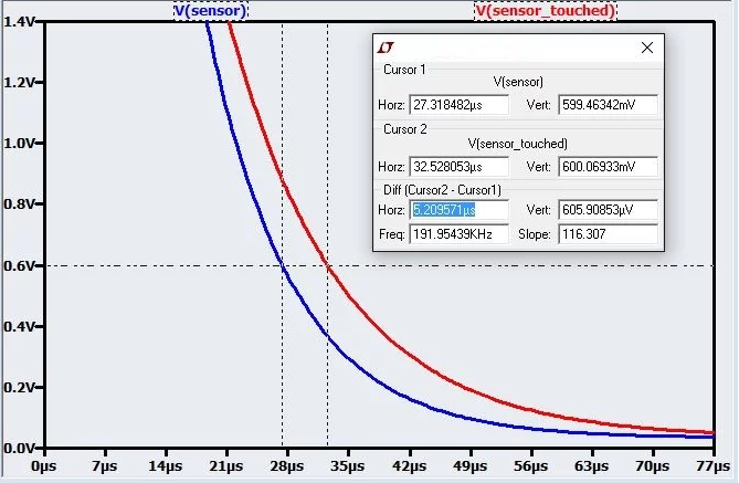
With a timer clock source period of 1/(25 MHz) = 40 ns, this ΔT corresponds to 130 clock cycles. Even if the change in capacitance is reduced by a factor of 10, there will still be a difference of 13 scales between an untouched sensor and a touched sensor.
So the idea here is to repeatedly charge and discharge the capacitor while monitoring the discharge time; if the discharge time exceeds a predetermined threshold, the microcontroller assumes that the finger is "in contact" with the touch-sensitive capacitor (I put "in contact" in quotes because the finger never actually touches the capacitor - as mentioned in the previous article, the capacitor is shielded from the external environment by the solder mask and the device housing). However, real life is a bit more complicated than the idealized discussion presented here; sources of error are discussed in the "Dealing with Reality" section below.
3. Frequency conversion capacitor
In a frequency shift based implementation, the capacitive sensor acts as the "C" part of an RC oscillator, so a change in capacitance results in a change in frequency. The output signal is used as the input to a counter block that counts the number of rising or falling edges that occur within a particular measurement period. When an approaching finger causes the sensor capacitance to increase, the frequency of the oscillator output signal decreases, so the number of edges decreases.
A so-called relaxation oscillator is a common circuit that can be used for this purpose. In addition to the touch-sensitive capacitor, it requires a few resistors and a comparator; this may seem more cumbersome than the charge/discharge technique discussed above, but if your microcontroller has an integrated comparator module, it's not too bad.
I'm not going to go into detail about this oscillator circuit because 1) it's discussed elsewhere, including here and here, and 2) it seems unlikely that you'd want to use the oscillator approach when there are so many microcontrollers and discrete ICs that offer high-performance capacitive touch-sensing capabilities. If you have no choice but to create your own capacitive touch-sensing circuit, I think the charge/discharge technique discussed above is simpler. Otherwise, make your life a little simpler by choosing a microcontroller with dedicated capacitive-sensing hardware.
The capacitance sensing peripheral in Silicon Labs' EFM32 microcontrollers is an example of an integrated module based on the relaxation oscillator approach:
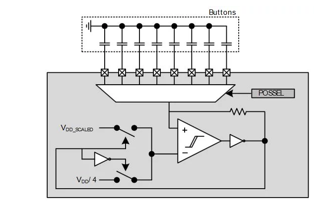
The multiplexer allows the oscillation frequency to be controlled by eight different touch-sensitive capacitors. By cycling the channels quickly, the chip can effectively monitor eight touch-sensitive buttons simultaneously because the operating frequency of the microcontroller is very high relative to the speed of finger movement.
4. Reality
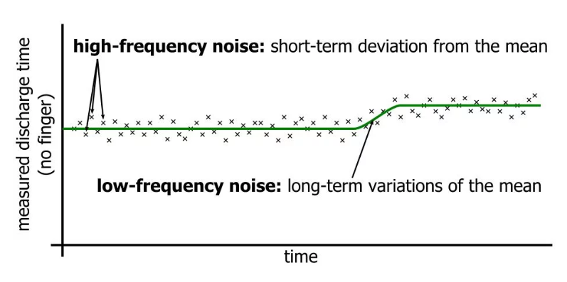
We must note that capacitive touch sensing systems will be plagued by both high-frequency and low-frequency noise.
High frequency noise can cause small sample-to-sample variations in the measured discharge time or edge count. For example, the discharge time for the fingerless charge/discharge circuit discussed above might be 675 clock cycles, then 685 clock cycles, then 665 clock cycles, then 670 clock cycles, and so on. The significance of this noise depends on the expected finger-induced variation in discharge time. If the capacitance increases by 30%, then ΔT
will be 130 ticks. If our high frequency variations are only about ±10 ticks, we can easily distinguish signal from noise.
However, a 30% increase in capacitance is probably close to the maximum change we can reasonably expect. If we only have a 3% chance, then ΔT is 13 ticks, which is too close to the noise floor. One way to reduce the effects of noise is to increase the amplitude of the signal, which you can do by reducing the physical separation between the PCB capacitor and your finger. However, mechanical design is often limited by other factors, so you have to make the most of any signal amplitude you get. In this case, you need to reduce the noise floor, which you can do through averaging.
For example, each new discharge time can be compared not to the previous discharge time, but to the average of the past 4, 8, or 32 discharge times. The frequency shifting technique discussed above automatically incorporates averaging because small changes around the average frequency do not significantly affect the number of cycles counted during a measurement period that is relatively long relative to the oscillation period.
Low-frequency noise refers to long-term changes in sensor capacitance when there is no finger; these can be caused by environmental conditions. This noise cannot be averaged out because the changes can last for a long time. Therefore, the only way to effectively deal with low-frequency noise is to be adaptive: the threshold used to identify the presence of a finger cannot be a fixed value. Instead, it should be adjusted periodically based on measurements that do not exhibit significant short-term changes, such as those caused by the proximity of a finger.
In summary, we note that capacitive touch sensing does not require complex hardware or highly sophisticated firmware. Nevertheless, it is a versatile, powerful technology that can provide significant performance improvements over mechanical alternatives.
- Signal diode arrays/configurations, freewheeling diode operation
- What is a Half Wave Rectifier? Working Principle of a Half Wave Rectifier
- How to read resistor color codes? Resistor color codes illustrated
- RC filter explained in detail
- Working principle/advantages/disadvantages/size of optical fiber
- Basic characteristics/working principles and application circuits of tunnel diodes
- Analysis of three simple electronic dice circuits
- Experimental circuit based on 4040 binary adder counter
- Touch circuit design and analysis
- LED lights that “drain” battery power
- 555 square wave oscillation circuit
- 555 photo exposure timer circuit diagram
- Introducing the CD4013 washing machine timer circuit diagram
- Simple level conversion circuit diagram
- 555 electronic guide speaker circuit diagram for blind people
- Circuit diagram of disconnection alarm composed of 555
- Analog circuit corrector circuit diagram
- color discrimination circuit
- Color sensor amplification circuit
- Level indication circuit


 京公网安备 11010802033920号