100W 2200m band transmitter amplifier
Source: InternetPublisher:8kSyqKlNQ Keywords: transmitter Updated: 2025/12/05
This particular transmitter was later shipped to VY1JA in the Yukon Territory, and thanks to Jay's excellent antenna system, it was heard in Europe and New Zealand during a trans-Pacific test! It produces 100 watts of power on a 50-ohm load when operating at 24 volts in the final stage.
This transmitter uses a 4060 binary counter IC chip as both a crystal oscillator and a divider. I used a 2200 kHz crystal and a "divide-by-6" output to generate a 137.5 kHz signal. Other crystal frequency and divide-by-6 combinations can also be used, as the 4060 has divide-by-6 outputs such as f/32 (pin 5) and f/64 (pin 4). You may have a 4MHz or 8MHz crystal in your parts box; using those output pins will allow you to get into that band.
I used a crystal thermostat from a very old taxi FM radio to mount the crystal, but without using the "thermostat" function. I found that the thermostat-controlled heating/cooling cycle produced more drift than simply turning off the thermostat. However, I lined both the inside and outside of the thermostat with foam, hoping to minimize temperature variations in the crystal. Initial testing suggests it works perfectly fine on the QRSS30 speed. I haven't tested it on the QRSS60 yet, where even the slightest drift would quickly become apparent.
The transmitter is simple in construction and inexpensive. The final stage of the IRF540 FET runs very cool, although a heatsink should probably be added. I have also used the IRF640, with almost no changes. All coils and transformers are wound on ABS or PVC tubing.
Transmitter schematic diagram
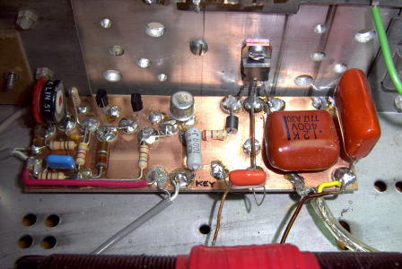
I used a "Manhattan-style" construction on the circuit board.
Transmitter PCB
Output transformer (T1) - wound on a 1.5-inch tube, approximately 5 inches long. First, wind the secondary winding, consisting of 80 turns of approximately #20 enameled wire. Then, wind the primary winding tightly, 15 turns of approximately #16 enameled wire, at the top center of the secondary winding. Before winding the primary, wrap the center portion of the secondary winding with PVC electrical tape or heavy-duty conduit Teflon tape.
Output filter (L1) - wound on a 2-inch tube, approximately 5 inches long. Wrap 80 turns of #20 wire tightly, tap at 40 turns, then tap every 5 turns until the end.
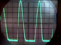
The capacitor used for the FET drain should be of high quality, such as polycarbonate or mica. Although the original design specified a 1 uF capacitor at the top of the T1 primary, I found that 2.2 uF gave a better waveform at the FET drain. Look for a typical Class E waveform at the drain.
Class E waveform
Operation - Mitch's version of this amplifier appears to be more efficient than the one I built. Running the final stage at 24VDC, with the FETs drawing about 6.5-7 amps and the input about 160W, the measured output is 95W, resulting in approximately 60% efficiency. A properly designed Class E amplifier should achieve higher efficiency, so this design still has significant room for improvement. One thing I'd like to do is experiment with the output transformer to optimize its performance. Perhaps rewinding it on a ferrite core would help. The output transformer generates a lot of heat, indicating significant power wastage. Perhaps the missing 30% efficiency can be recovered there.
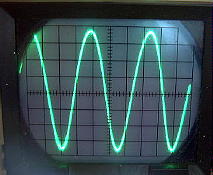
Operate the transmitter into a 50-ohm dummy load or your resonant (50-ohm) antenna system. You may want to "tune up" at a lower voltage and then increase the drain voltage after adjustment. Start by tapping the antenna at the coaxial end of the filter coil. As you tap closer to the center, the power output will increase, and the drain current of the final stage amplifier will also increase. You will reach a point where the output no longer increases further, even as the drain current increases. Tap at the point of optimal efficiency. The output waveform should be a clean sine wave.
Output waveform
I ran this transmitter overnight on several occasions, and it performed very well for such a simple design with the QRSS30. I used the K1EL QRSS keyer chip to generate the QRSS beacon keying or ON7YD's free "QRSS" software (available on his website).
- BA1404 transmitter with UPC1651 RF amplifier
- Portable FM transmitter
- Remote FM transmitter circuit
- FM telephone transmitter
- 2km FM transmitter
- Understand the inner workings of the CAN bus driver and how to debug the system
- 9018 single-tube FM transmitter circuit diagram
- High-quality banner/FM radio circuit
- RF Power Monitoring Circuit
- MICRFl02 ASK 470~300 MHz Transmitter
- Infrared light emission circuit
- Ultrasonic remote control circuit a composed of T-40-16
- Lightwave voice communication transmitter circuit diagram
- Infrared remote control light switch
- Four-channel remote control switch transmitter circuit
- Single channel dual channel power remote control switch transmitter circuit
- transmitter toy circuit
- Long distance infrared alarm switch circuit transmitter circuit
- FM transmitter circuit 04
- FM transmitter circuit 01


 京公网安备 11010802033920号