1 km power FM transmitter
Source: InternetPublisher:K1AyYG4mJ Keywords: FM transmitter Updated: 2025/12/12
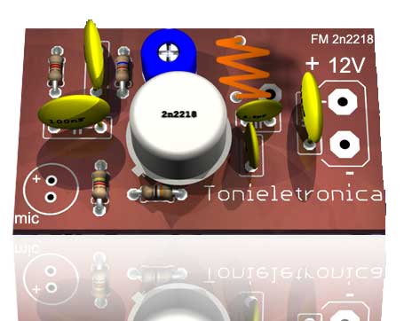
This low-power FM transmitter can transmit over 1 kilometer under good conditions. Modulation can be done via a microphone or audio source. The power FM transmitter circuitry is built around a 2N2218 transistor. The transmitter coil is a 5-turn 22 AWG enameled wire, 1 cm in diameter, without a magnetic core. Note that the capacitor should be ceramic. The antenna length should be 15 to 40 cm. For transmission, place an FM receiver (radio) close to the transmitter, turn the volume to half, and on an idle frequency (without other stations operating), use a wooden or plastic key to rotate the screw of the variable capacitor (CV) to capture the transmitter's frequency.
If installation is difficult, remove the coil and rewind it, with varying numbers of turns. Refer to the pinout of the 2N2218 transistor. Mic1 is a dual-ended electret microphone; resistor R1 is used for microphone bias and may need adjustment to suit your microphone; values from 1k to 10k are acceptable. A fiberglass board is preferable, as it is suitable for high frequencies. For better frequency stability, the antenna may need to be placed on the second turn of the coil; solder the antenna piece to the second turn of coil L1.
Below is one of the schematic diagrams for an FM transmitter circuit.
List of materials for assembling the FM transmitter
5% 1/4 W resistor:
R1 = 3 to 10kΩ (black, black, orange, gold)
R2 = 6.8kΩ (blue, gray, red, gold).
R3 = 4.7kΩ (yellow, purple, red, gold).
R4 = 39Ω (orange, white, black, gold).
ceramic capacitors
C1 = 4.7 nF (472 or 4n7 or 4700)
C2 = 2.2 nF (2200 or 2n2 or 222)
C3 = 4.7 pF (4p7 or 4.7)
C4 = 100 nF (100n or 0.1 or 104)
C5 = Fine-tuning capacitor CV 3-30 pF.
transistor:
T1 = 2N2218 or equivalent model number.
other:
L1 = See text
B1 = 9-volt alkaline battery.
Mic1 = electret microphone.
Other = Printed circuit boards, antennas, boxes, etc.
FM transmitter circuit board copper ratio 3:1
FM transmitter circuit board component side
The pin arrangement of transistor 2N2218 is shown in the figure below.
User electronic tag:
2N2218, FM transmitter circuit approximately 1 km, transmitter FM 2N2218.
- 8W PLL phase-locked loop stereo transmitter with LCD display
- TDA7088 receiver
- Simple FM radio
- Portable FM transmitter
- Small amplitude modulation transmitter
- Remote FM transmitter circuit
- FM telephone transmitter
- BA1404 Stereo FM Transmitter (with Amplifier)
- 2km FM transmitter
- HXl000 00K 433.92 MHz Transmitter Module
- USB communication circuit
- Indoor unit communication circuit
- Crystal oscillator 80mW FM transmitter production circuit diagram
- Two-way communication circuit circuit diagram
- 2m, 2W phase-locked FM transmitter
- Long distance serial communication circuit
- CAN bus communication circuit
- Wireless transmitter circuit diagram
- Time division multiplexing stereo decoder circuit
- Design of wireless transmitting and receiving circuit based on Bluetooth


 京公网安备 11010802033920号