Aircraft radio receiver
Source: InternetPublisher:POFiON1py Keywords: radio receiver Updated: 2025/11/11
Communications between commercial aircraft and the ground can be interesting, entertaining, and even unsettling at times. However, radio equipment capable of receiving frequencies ranging from approximately 220 MHz to 400 MHz (commonly used in aircraft, both military and commercial) is not readily available. Furthermore, scanners can be complex, bulky, and expensive. With such an easily constructed circuit, anyone can enjoy listening to these conversations.
Listening to aircraft/aviation communications is fascinating, and this electronic circuit offers a viable alternative to the very expensive commercial radio scanners on the market. Fantastic for us enthusiasts!
The electronic circuitry for this aircraft receiver was first published in the Think Tank column of Popular Electronics magazine in September 1995. It appears to be very simple to build, with only about 20 electronic components.
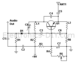
L1 is made by winding 2 turns of 22 AWG magnetic wire on a 5/32 drill bit. This inductor can be modified to change the frequency range of the circuit. If an overload problem occurs when the antenna is connected to the emitter of Q1, the antenna can also be placed at the anode of D1. R5 adjusts the regeneration, thereby adjusting the sensitivity.
Component List:
R1, R3 - 47 kΩ 1/4 W resistor;
R2 - 10 kΩ 1/4 W resistor;
R4 - 4.7 kΩ 1/4 W resistor;
R5 - 5 kΩ linear taper potentiometer;
R6 - 2.2 kΩ 1/4 W resistor;
C1, C2, C3, C6 - 0.001 μF ceramic disk capacitor;
C4 - 2.2 picofarad ceramic disk capacitor;
C5 - 1 picofarad ceramic disk capacitor;
C7 - 15 μF 15 V electrolytic capacitor;
C8 - 18 picofarad variable capacitor;
D1 - 1N82 diode;
Q1 - 2N918 NPN transistor;
L1 - see notes;
L2 - 1.8 μH inductor
; ANT1 - approximately 18 inch wire antenna;
MISC - printed circuit board, wires, C8 knob.
Technical Specifications
: Power Supply Voltage: 9-12 volts;
Operating Frequency: 220 MHz - 400 MHz
- 8W PLL phase-locked loop stereo transmitter with LCD display
- BH1417 USB FM Transmitter
- TDA7088 receiver
- 100W 2200m band transmitter amplifier
- 1-watt portable PLL transmitter
- Single-tube voltage-controlled oscillator frequency modulation transmitter
- TDA7000 single-chip FM radio circuit diagram
- HXl000 00K 433.92 MHz Transmitter Module
- XEl201A FSK 300~500 MHz transceiver
- Superheterodyne receiver module CS906
- USB communication circuit
- Indoor unit communication circuit
- Low frequency amplifier circuit for radio receiver
- Two-way communication circuit circuit diagram
- Long distance serial communication circuit
- CAN bus communication circuit
- Wireless transmitter circuit diagram
- Time division multiplexing stereo decoder circuit
- Design of wireless transmitting and receiving circuit based on Bluetooth
- Fiber optic transceiver circuit diagram


 京公网安备 11010802033920号