USB sound card using PCM2902
Source: InternetPublisher:p3cdh1KD Keywords: USB sound card Updated: 2026/03/06
USB sound card and PCM2902
This is a USB sound card using the PCM2902 chip. To test the digital-to-analog converter, I built a simple USB sound card using the PCM2902 circuitry. The card features analog inputs and outputs, electrical S/PDIF outputs, isolated inputs, and optical inputs and outputs (TOSLINK). At the heart of the USB sound card is the PCM2902, a complete USB codec circuit. This circuitry can handle sampling frequencies up to 48kHz. The integrated circuits include a USB controller for the analog-to-digital converter and digital-to-analog converter, an HID section for three buttons, volume control, a custom converter, and an S/PDIF encoder and decoder.

USB sound card and PCM2902
The circuit design is based on the datasheet's recommended configuration. An external voltage regulator circuit IC2 is used to improve analog output quality. All supply voltages are decoupled via a 1uF capacitor. The circuit also connects the optical transmitter and receiver TOTX173 and TORX173. The electrical S/PDIF output is implemented via an RS422 transmitter IC4. Since commercial S/PDIF coaxial cable transmission uses an unbalanced 75-ohm impedance, I used only one output and reduced the output voltage and adjusted the output impedance to a standard value using resistor dividers R13/R14. The output voltage is displayed as 0.6V peak-to-peak most of the time. The output divider voltage is slightly higher, but this should have no impact. The S/PDIF receiver also includes an RS422 driver, which is used as a TTL converter in this case. The input is terminated by resistor R7, which can be placed before or after the pulse transformer. I found it more effective when using the resistor before the transformer; the pulse waveform on the oscilloscope was clearer. The digital input is connected via an electrical/optical switch. The circuit automatically switches from analog to digital mode if an S/PDIF signal is detected. The analog output does not include an external amplifier, so it cannot be directly connected to low-impedance headphones. Connecting to an amplifier is recommended.
No special drivers are required. I tested all functions on Linux, Windows XP, and Windows 7, with the drivers included in the operating system. The HID button, volume control, and mute function work perfectly.
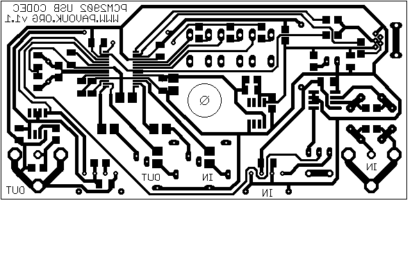
wiring
Chart format Eagle 5
welding
We placed the PCB components in ascending order of size. First, we soldered circuit IC1, which is very small. I used micro-soldering to secure the two corner pins. After confirming accurate circuit positioning, I applied liquid flux to all pins to facilitate solder flow, then used a soldering iron and solder tip to solder one side first, then the other. Many pins were soldered together. Excess solder was easily removed using copper braided wire, which was specifically designed for this purpose. Next, we soldered the other circuits, continuing with the SMD resistors and capacitors. Then we placed the jumpers, all the top components, and the end connectors.
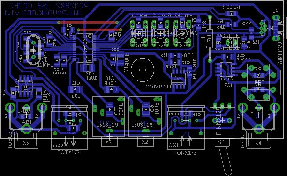
Layout planning
PCB
The PCB is designed as a single-sided board with two jumper wires. This makes it easy to assemble under amateur conditions. Its dimensions match the U-KP35B plastic case. After assembly, I found that the switch input connection was reversed. The link here has been corrected. The SMD component is 1206, which is well-positioned for good soldering.
PDF format Eagle5
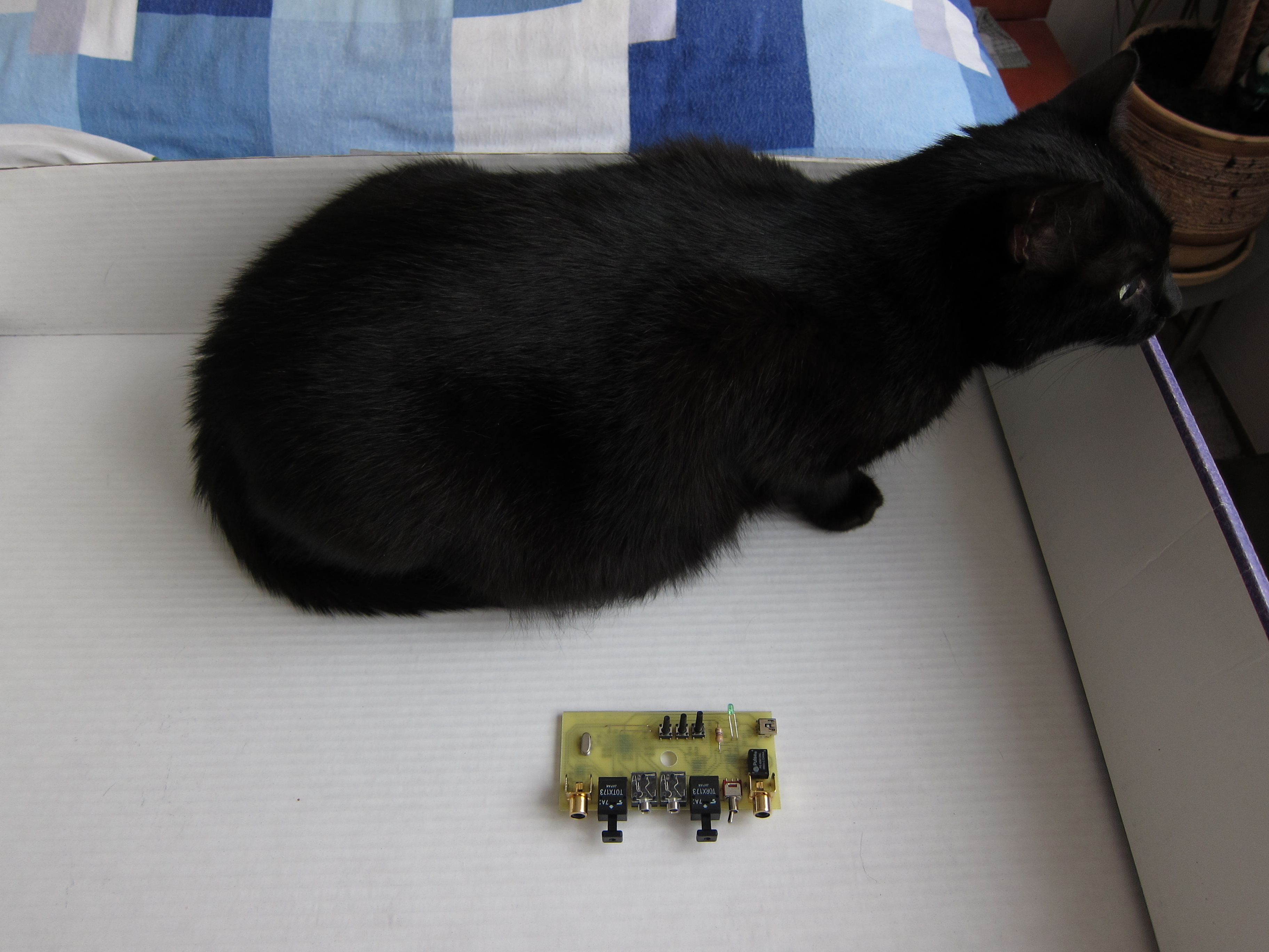
photo
Components
Most components were purchased from GM Electronic. The USB connector is from GES Electronic, and the IC PCM2902 was sold by FK Technics, etc. The pulse transformer was purchased from eBay, specifically model PE-65612. If you don't mind the input not being isolated, you can replace it with two 100nF capacitors.
Component list
Identifier value and number of types
R1-R2 SMD1206 22R 2 pieces
R3 1M SMD1206 1 piece
R4, R9-R11 SMD1206 1K5 4 pieces
R5 180k SMD1206 1 unit
R6 91k SMD1206 1 unit
R7 SMD1206 75R 1 piece
R8 2R2 SMD1206 1 piece
R12 SMD1206 8K2 1 piece
R13 SMD1206 360R 1 piece
R14 SMD1206 91R 1 piece
R15 SMD1206 330R 1 piece
C1-C8 1uF Ceramic SMD1206 (8 pieces)
C9-C14 10uF/25V Electrolytic Capacitors, SMD Size B, 6 pieces
C15-C16 22pF Ceramic SMD1206 (2 pieces)
C17 10nF Ceramic SMD1206 1 piece
C18-C20 100nF Ceramic SMD1206 (3 pieces)
IC1 PCM2902, PCM2902B 1 unit
IC2 LP2951CM SMD SO-08 1 piece
IC3-IC4 75176B SMD SO-08 2 pieces
L1 47uH Axial 1
LED1 2 mA Green LED 1 piece
OX1 TORX173 Toshiba 1 unit
OX2 TOTX173 Toshiba 1 unit
Q1 12MHz mini crystal (1 unit)
Three S1-S3 6x6mm high-precision microswitches
S4 P-switch KNX125 1 unit
TR1 LL1572 or S22083 or PE-65612 1 piece
X1 USB miniUSB socket PCB MBW 1 unit
X2-X3 3.5-inch EBS35 jacks (2 pieces)
X4-X5 RCA socket PCB TOBU3 2
Krab1 plastic box U-23 mm x 54 mm x 104 mm KP35B 1 piece
in conclusion
The connections are reliable. Measurements generally conform to the datasheet. If only some inputs or outputs are used, it's unnecessary to assemble all connectors. In addition to the PCM2902 circuitry, expensive optical transceivers and transformers should also be considered. This wiring can be used as a second sound card or as an S/PDIF output connected to a stereo amplifier with digital inputs. The digital inputs can be connected to other digital audio sources such as DAT, MiniDisc, CD players, etc. For parameter measurement, I used RightMark Audio Analyzer (RMAA) and Baudline. In RMAA, the results under Windows 7 were significantly worse than under Windows XP. Volume control also exhibited anomalies. I only performed tests under Linux, as shown in the illustration.

- Gain Cloning Power Amplifier LM3886
- Stereo code multiplexer
- TDA1011 6.5W Power Amplifier
- Hybrid headphone amplifier
- DS1802 Stereo Digital Volume Controller
- 25-watt MOSFET audio amplifier
- Portable headphone amplifier
- 5 Watt Class A Audio Amplifier
- Make a pocket amplifier with 8550 and 8050
- Upgrading the negative feedback circuit of the MT12 tube amplifier
- LA4461N audio IC circuit
- TDA2030 audio power amplifier circuit diagram
- Voice controlled bird circuit
- Transistor Audio Mixer Circuit Diagram
- 2-tube FM microphone with 3V power supply
- Simulating bird call circuit schematic diagram
- Several good field effect transistor power amplifier circuit diagrams
- Squelch Tuned Audio Switching/Mixing Circuit Diagram
- transistor audio mixer
- High quality melody circuit


 京公网安备 11010802033920号