Digital potentiometer with storage function
Source: InternetPublisher:NRJSxe Keywords: Digital potentiometer Updated: 2025/11/18
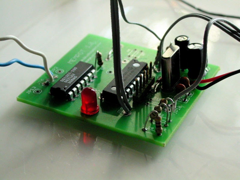
The digital potentiometer with memory is built on the PIC 16F819 microcontroller. It reads analog resistance values, records them into memory, and then plays them back via the DS1267 digital potentiometer chip. The memory buffer size and playback speed are adjustable.

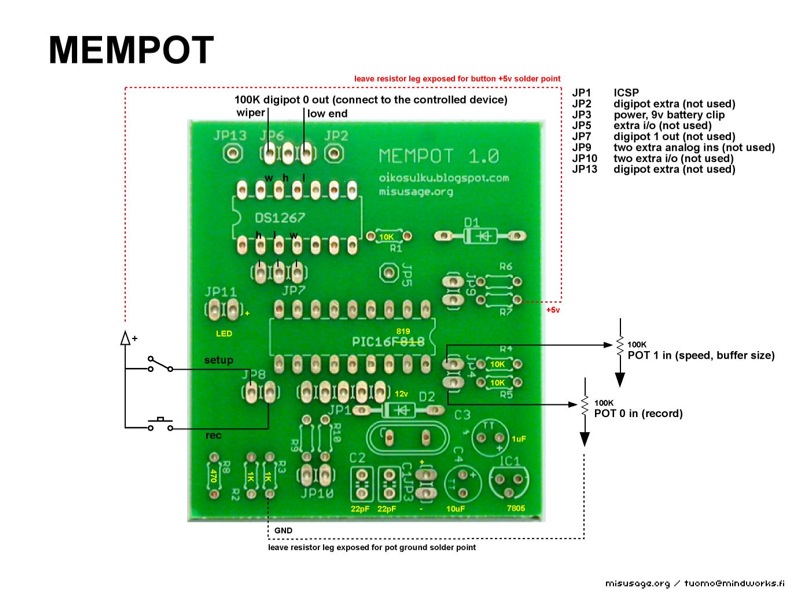
The digital potentiometers were the first circuit design we finally created with a proper PCB. It was a rewarding experience, though not without its problems. During the design process, I taught myself the widely used Eagle CAD software, and there were a few things I overlooked. First, I mistakenly selected a resistor package that was too small from the library, so the most common 6mm resistors couldn't be mounted horizontally and had to be soldered vertically. Fortunately, this wasn't a major issue. Another, slightly more inconvenient, problem was that I forgot to set extra solder points for GND and +5V for the interface (off-board), so GND and +5V had to be connected to exposed points on the board when connecting the switches and potentiometers. Coincidentally, the exposed pins of the vertically soldered resistors were perfect for this, so the first mistake somewhat solved the second.
Making a digital potentiometer with a PCB is straightforward. You can solder the components in any order, but I usually solder the chip first. There's an ICSP socket for updating the PIC code, so using an IC socket isn't always necessary. If you're concerned about damaging the chip, use a socket for both the PIC and the digital potentiometer chip. If you don't have a PIC programmer with an ICSP port, you'll naturally need to program the PIC first and then use the socket to update the software.
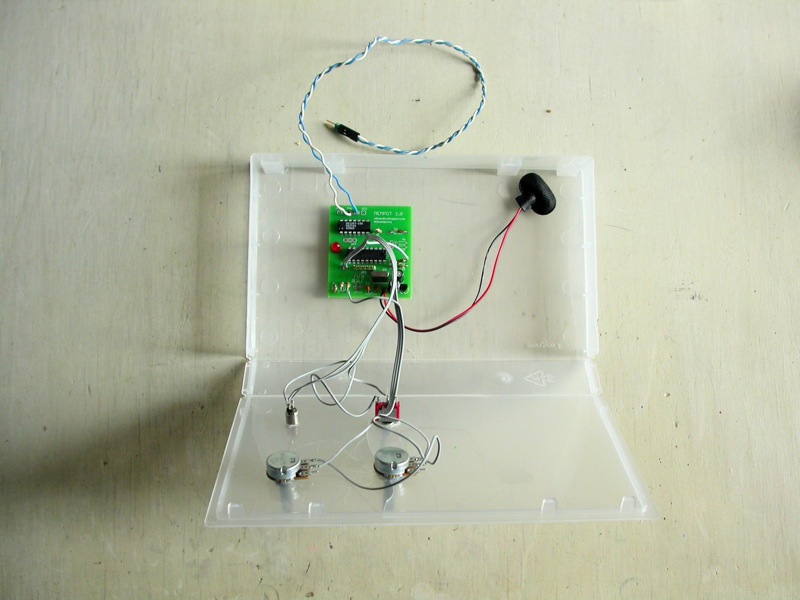
Once you have the circuit board complete, you can test some of the functionality before interface work. If you power the board, the LED indicating the setting mode will blink a few times and then turn off. Next is the interface. Before connecting the switches and potentiometers, you'll need to make some decisions about the chassis and determine how much wire length is required from the circuit board to the panel. Drill holes for the potentiometers, switches, and LEDs and mount them to the panel. Once they are in place on the panel, connecting them to the circuitry is easier. Solder the wires according to the diagram below.
use
A digital potentiometer is a controller, so you'll need something to control it. Simple sound makers like NandSynth or APCs with resistor-controlled pitch will suffice. If you have some circuit-bending instruments where potentiometers or LDRs control certain functions, connect a digital potentiometer there. This first-version digital potentiometer has two 100K resistor outputs, and we're using one of them. You can connect a larger physical potentiometer in series with the digital potentiometer output to change the range, for example, from 0K-100K to 500K-600K.
Power on the circuit board; the preset buffer should play back, looping the linear ramp of the 0-100K resistor. Adjust the playback speed using the speed potentiometer. Press and hold the record button and adjust the record potentiometer; the LED will start flashing. When you release the record button, the recorded adjustment should loop back. The digital potentiometer overlays the recording, so when the buffer is full, it overwrites the memory from the beginning. You can change the buffer size by toggling the switch into setup mode. The LED lights up in setup mode. Now you can use the speed potentiometer to change the buffer size. Try a very short buffer by turning the potentiometer almost counterclockwise all the way. Exit setup mode from the switch; the beginning of the previously recorded buffer should play back.
improve
Indicators for speed and buffer size are missing. I've used a serial LCD screen or PC to debug the values, but a simple indicator with a few LEDs would also work. For a closed chassis, a power switch and a power LED would be useful. A switching mode between overlay recording and one-shot recording, and a sync signal from an extra pin at the start of the loop each time it passes, would be helpful.
- PIC USB interface based on FT245
- Microchip's MCP73831 lithium-ion battery charging management chip
- Relay timer based on PIC16F628
- Interface circuit between PDIUSBD12 chip and 51 single-chip microcomputer
- What is the mechanism of microcontroller latch-up?
- How does MCU handle interrupts? MCU interrupt processing process
- Introduction to MCU GPIO Interface
- Make an alcohol tester based on 8051 microcontroller
- What is the difference between RISC-V, ARM and x86 microprocessors?
- Circuit diagram of multifunctional digital clock


 京公网安备 11010802033920号