Relay timer based on PIC16F628
Source: InternetPublisher:OkkvMnBM Keywords: PIC16F628 relay timer Updated: 2025/12/02
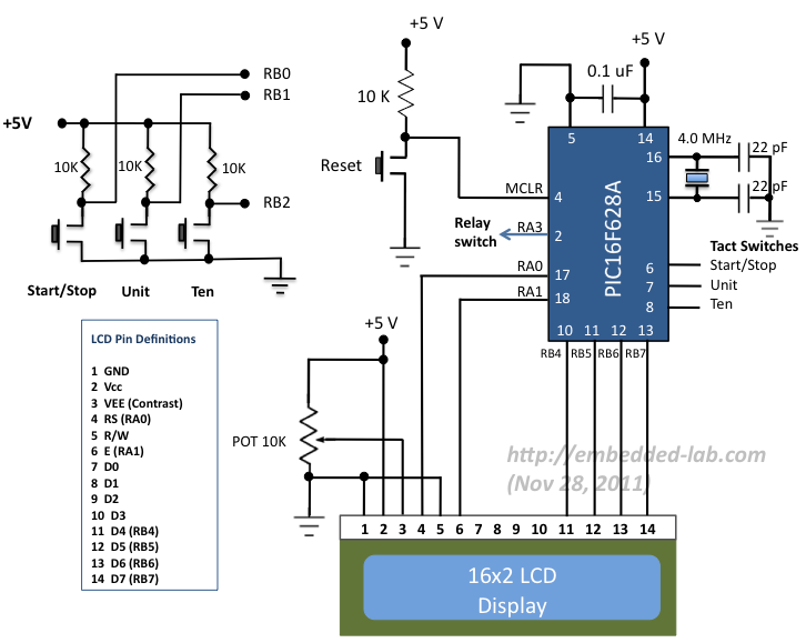
This is a 0-99 minute relay timer using a PIC16F628 microcontroller and a 16-character LCD display. The microcontroller is a PIC16F628A, running at a 4.0 MHz clock speed and using an external crystal. The 16×2 character LCD based on the HD44780 is the main display unit of the project. You can view and set the timer duration via haptic switches. There are three haptic switches connected to the RB0 (start/stop), RB1 (units), and RB2 (tens) pins. You can use the unit and tens minute switches to select the timer interval from 0 to 99 minutes. The start/stop switch is used to toggle the timer on and off. When the timer is on, a logic high signal appears on the RA3 pin, which can be used to turn on the relay. The circuit diagram for this project is shown below.
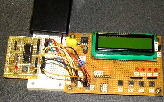
While browsing through my old backup hard drive, I found the source code for a very simple PIC-based digital timer that I made a few years ago. The actual hardware for the project is no longer with me; it was likely lost when I moved from my old apartment to a new one. However, I thought it might be a good practice project for beginners, so I'm sharing it here. I'm not planning to rebuild it from scratch; instead, I'll demonstrate it using my homemade PIC16F628A breadboard module and I/O board. The complete circuit diagram and firmware developed using the mikroC Pro for PIC compiler are provided in the article.
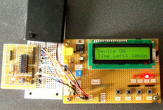
I'm demonstrating this project here using my homemade PIC16F628A breadboard module and Experimenter I/O board. Since there are no relay switches on the I/O board, I've connected the timer output (pin RA3) to an LED. The LED lights up when the timer starts and turns off when the timer's duration ends.
Circuit setup
Timer operation
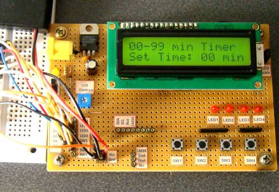
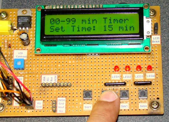
When the device is powered on, the microcontroller initializes the LCD display and displays the following message. The timer is initially off, so the LED or relay connected to the RA3 pin is also off.
Message displayed when power is on
You can use the unit and ten-digit haptic switches to set the time duration from 00 to 99 minutes (in 1-minute increments). Each press of the switch increments the corresponding time number.
Set timer minutes
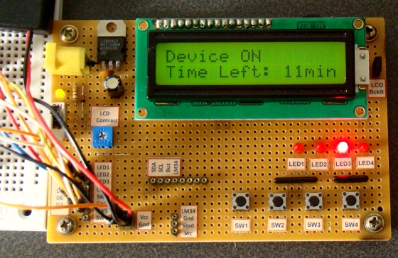
After setting the desired time, press the start/stop switch to start the timer. The RA3 pin goes high (LED illuminates), and the countdown begins. While the timer is running, the remaining time will also be displayed on the LCD screen. When the time is up, the timer stops, and the LED turns off. You can interrupt and stop the timer at any time by pressing the start/stop switch again.
Display the remaining time on the LCD.
software
The PIC firmware was developed using the mikroC Pro for PIC compiler. For simplicity, timers were avoided. The time delay was created using mikroC's Delay_ms() function, which appears to provide fairly accurate time delays.
Download mikroC source code and HEX files
- PIC Dual-channel Thermometer
- PIC USB interface based on FT245
- PIC18F2445 USB Experimental I/O Board
- USB data acquisition based on PIC18F4550
- Arduino DCC Decoder
- USB data acquisition based on PIC18F4550
- Relay timer based on PIC16F628
- Why does a single-chip microcomputer need an external crystal oscillator? Crystal oscillator working principle and circuit diagram analysis
- Working principle of DCC module, practical application and precautions of DCC module
- Circuit diagram of multifunctional digital clock
- 60Hz time base generator composed of MM5369
- Touch desk lamp circuit
- Water inlet motor protection circuit
- Delay circuit using operational amplifier
- Simple battery charging and discharging automatic control device circuit
- Delay energy-saving lamp timer
- Timer for automatic insertion keyer
- electronic timer
- Appliance on/off cycle timer
- 9V charger with digital circuit timer


 京公网安备 11010802033920号